YAMAHA WR 400F 2001 Betriebsanleitungen (in German)
Manufacturer: YAMAHA, Model Year: 2001, Model line: WR 400F, Model: YAMAHA WR 400F 2001Pages: 762, PDF-Größe: 62.36 MB
Page 631 of 762
5 - 43
CHAS
GUIDON
LENKER
MANILLAR
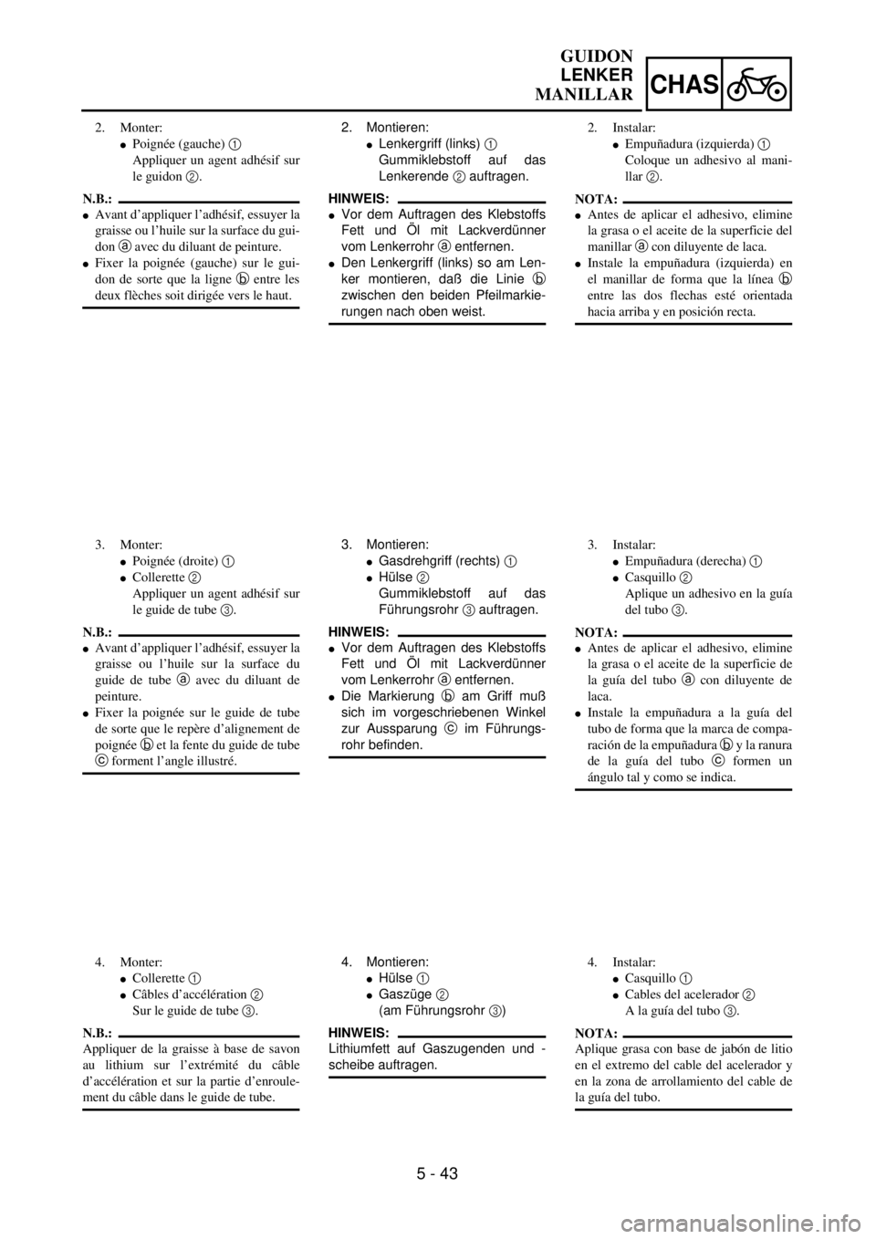
2. Montieren:
lLenkergriff (links) 1
Gummiklebstoff auf das
Lenkerende 2 auftragen.
HINWEIS:
lVor dem Auftragen des Klebstoffs
Fett und Öl mit Lackverdünner
vom Lenkerrohr a entfernen.
lDen Lenkergriff (links) so am Len-
ker montieren, daß die Linie b
zwischen den beiden Pfeilmarkie-
rungen nach oben weist.
3. Montieren:
lGasdrehgriff (rechts) 1
lHülse 2
Gummiklebstoff auf das
Führungsrohr 3 auftragen.
HINWEIS:
lVor dem Auftragen des Klebstoffs
Fett und Öl mit Lackverdünner
vom Lenkerrohr a entfernen.
lDie Markierung b am Griff muß
sich im vorgeschriebenen Winkel
zur Aussparung c im Führungs-
rohr befinden.
4. Montieren:
lHülse 1
lGaszüge 2
(am Führungsrohr 3)
HINWEIS:
Lithiumfett auf Gaszugenden und -
scheibe auftragen. 2. Monter:
lPoignée (gauche) 1
Appliquer un agent adhésif sur
le guidon 2.
N.B.:
lAvant d’appliquer l’adhésif, essuyer la
graisse ou l’huile sur la surface du gui-
don a avec du diluant de peinture.
lFixer la poignée (gauche) sur le gui-
don de sorte que la ligne b entre les
deux flèches soit dirigée vers le haut.
3. Monter:
lPoignée (droite) 1
lCollerette 2
Appliquer un agent adhésif sur
le guide de tube 3.
N.B.:
lAvant d’appliquer l’adhésif, essuyer la
graisse ou l’huile sur la surface du
guide de tube a avec du diluant de
peinture.
lFixer la poignée sur le guide de tube
de sorte que le repère d’alignement de
poignée b et la fente du guide de tube
c forment l’angle illustré.
4. Monter:
lCollerette 1
lCâbles d’accélération 2
Sur le guide de tube 3.
N.B.:
Appliquer de la graisse à base de savon
au lithium sur l’extrémité du câble
d’accélération et sur la partie d’enroule-
ment du câble dans le guide de tube.2. Instalar:
lEmpuñadura (izquierda) 1
Coloque un adhesivo al mani-
llar 2.
NOTA:
lAntes de aplicar el adhesivo, elimine
la grasa o el aceite de la superficie del
manillar a con diluyente de laca.
lInstale la empuñadura (izquierda) en
el manillar de forma que la línea b
entre las dos flechas esté orientada
hacia arriba y en posición recta.
3. Instalar:
lEmpuñadura (derecha) 1
lCasquillo 2
Aplique un adhesivo en la guía
del tubo 3.
NOTA:
lAntes de aplicar el adhesivo, elimine
la grasa o el aceite de la superficie de
la guía del tubo a con diluyente de
laca.
lInstale la empuñadura a la guía del
tubo de forma que la marca de compa-
ración de la empuñadura b y la ranura
de la guía del tubo c formen un
ángulo tal y como se indica.
4. Instalar:
lCasquillo 1
lCables del acelerador 2
A la guía del tubo 3.
NOTA:
Aplique grasa con base de jabón de litio
en el extremo del cable del acelerador y
en la zona de arrollamiento del cable de
la guía del tubo.
Page 632 of 762
5 - 44
CHASHANDLEBAR
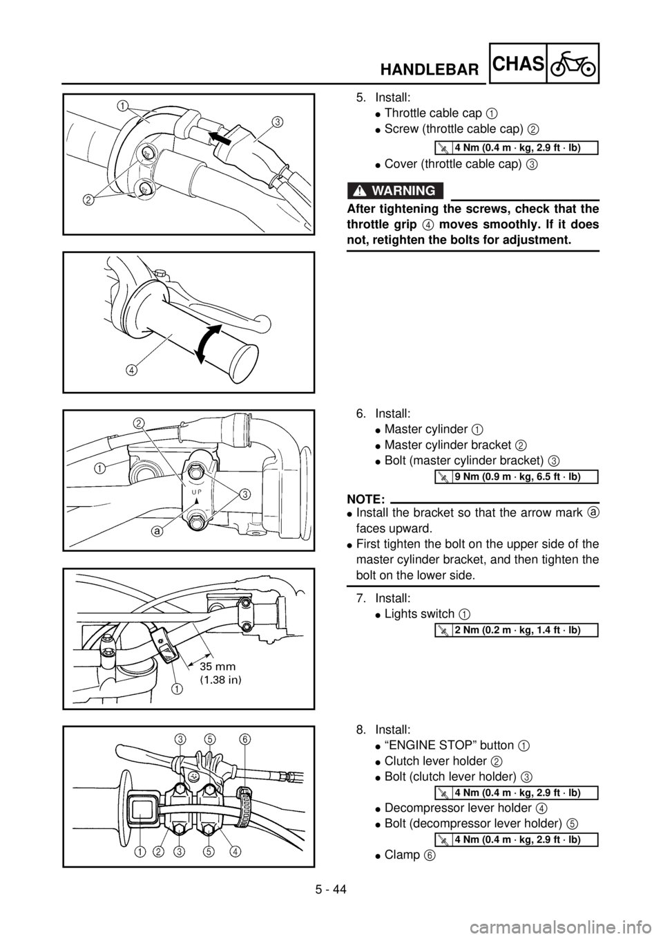
5. Install:
lThrottle cable cap 1
lScrew (throttle cable cap) 2
lCover (throttle cable cap) 3
WARNING
After tightening the screws, check that the
throttle grip 4 moves smoothly. If it does
not, retighten the bolts for adjustment.
T R..4 Nm (0.4 m · kg, 2.9 ft · lb)
6. Install:
lMaster cylinder 1
lMaster cylinder bracket 2
lBolt (master cylinder bracket) 3
NOTE:
lInstall the bracket so that the arrow mark a
faces upward.
lFirst tighten the bolt on the upper side of the
master cylinder bracket, and then tighten the
bolt on the lower side.
7. Install:
lLights switch 1
T R..9 Nm (0.9 m · kg, 6.5 ft · lb)
T R..2 Nm (0.2 m · kg, 1.4 ft · lb)
8. Install:
l“ENGINE STOP” button 1
lClutch lever holder 2
lBolt (clutch lever holder) 3
lDecompressor lever holder 4
lBolt (decompressor lever holder) 5
lClamp 6
T R..4 Nm (0.4 m · kg, 2.9 ft · lb)
T R..4 Nm (0.4 m · kg, 2.9 ft · lb)
Page 633 of 762
5 - 44
CHAS
GUIDON
LENKER
MANILLAR
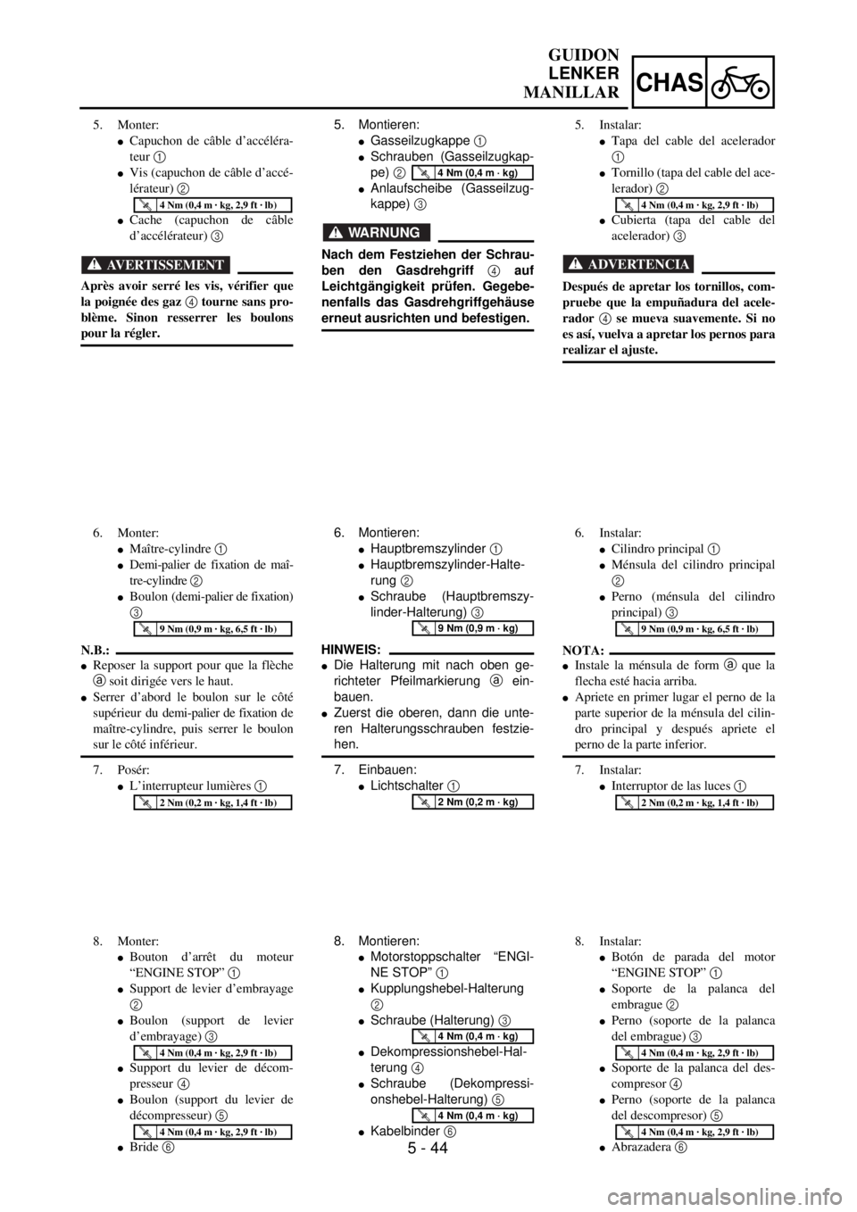
5. Montieren:
lGasseilzugkappe 1
lSchrauben (Gasseilzugkap-
pe) 2
lAnlaufscheibe (Gasseilzug-
kappe) 3
WARNUNG
Nach dem Festziehen der Schrau-
ben den Gasdrehgriff 4 auf
Leichtgängigkeit prüfen. Gegebe-
nenfalls das Gasdrehgriffgehäuse
erneut ausrichten und befestigen.
T R..4 Nm (0,4 m · kg)
6. Montieren:
lHauptbremszylinder 1
lHauptbremszylinder-Halte-
rung 2
lSchraube (Hauptbremszy-
linder-Halterung) 3
HINWEIS:
lDie Halterung mit nach oben ge-
richteter Pfeilmarkierung a ein-
bauen.
lZuerst die oberen, dann die unte-
ren Halterungsschrauben festzie-
hen.
7. Einbauen:
lLichtschalter 1
T R..9 Nm (0,9 m · kg)
T R..2 Nm (0,2 m · kg)
8. Montieren:
lMotorstoppschalter “ENGI-
NE STOP” 1
lKupplungshebel-Halterung
2
lSchraube (Halterung) 3
lDekompressionshebel-Hal-
terung 4
lSchraube (Dekompressi-
onshebel-Halterung) 5
lKabelbinder 6
T R..4 Nm (0,4 m · kg)
T R..4 Nm (0,4 m · kg)
5. Monter:
lCapuchon de câble d’accéléra-
teur 1
lVis (capuchon de câble d’accé-
lérateur) 2
lCache (capuchon de câble
d’accélérateur) 3
AVERTISSEMENT
Après avoir serré les vis, vérifier que
la poignée des gaz 4 tourne sans pro-
blème. Sinon resserrer les boulons
pour la régler.
T R..4 Nm (0,4 m · kg, 2,9 ft · lb)
6. Monter:
lMaître-cylindre 1
lDemi-palier de fixation de maî-
tre-cylindre 2
lBoulon (demi-palier de fixation)
3
N.B.:
lReposer la support pour que la flèche
a soit dirigée vers le haut.
lSerrer d’abord le boulon sur le côté
supérieur du demi-palier de fixation de
maître-cylindre, puis serrer le boulon
sur le côté inférieur.
7. Posér:
lL’interrupteur lumières 1
T R..9 Nm (0,9 m · kg, 6,5 ft · lb)
T R..2 Nm (0,2 m · kg, 1,4 ft · lb)
8. Monter:
lBouton d’arrêt du moteur
“ENGINE STOP” 1
lSupport de levier d’embrayage
2
lBoulon (support de levier
d’embrayage) 3
lSupport du levier de décom-
presseur
4
lBoulon (support du levier de
décompresseur) 5
lBride 6
T R..4 Nm (0,4 m · kg, 2,9 ft · lb)
T R..4 Nm (0,4 m · kg, 2,9 ft · lb)
5. Instalar:
lTapa del cable del acelerador
1
lTornillo (tapa del cable del ace-
lerador) 2
lCubierta (tapa del cable del
acelerador) 3
ADVERTENCIA
Después de apretar los tornillos, com-
pruebe que la empuñadura del acele-
rador 4 se mueva suavemente. Si no
es así, vuelva a apretar los pernos para
realizar el ajuste.
T R..4 Nm (0,4 m · kg, 2,9 ft · lb)
6. Instalar:
lCilindro principal 1
lMénsula del cilindro principal
2
lPerno (ménsula del cilindro
principal) 3
NOTA:
lInstale la ménsula de form a que la
flecha esté hacia arriba.
lApriete en primer lugar el perno de la
parte superior de la ménsula del cilin-
dro principal y después apriete el
perno de la parte inferior.
7. Instalar:
lInterruptor de las luces 1
T R..9 Nm (0,9 m · kg, 6,5 ft · lb)
T R..2 Nm (0,2 m · kg, 1,4 ft · lb)
8. Instalar:
lBotón de parada del motor
“ENGINE STOP” 1
lSoporte de la palanca del
embrague 2
lPerno (soporte de la palanca
del embrague) 3
lSoporte de la palanca del des-
compresor 4
lPerno (soporte de la palanca
del descompresor) 5
lAbrazadera 6
T R..4 Nm (0,4 m · kg, 2,9 ft · lb)
T R..4 Nm (0,4 m · kg, 2,9 ft · lb)
Page 634 of 762
5 - 45
CHASHANDLEBAR
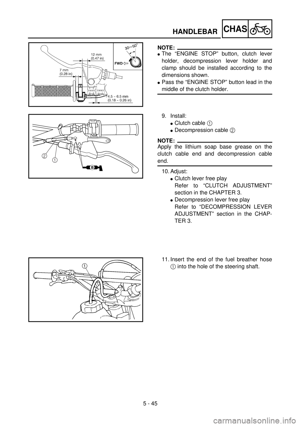
NOTE:
lThe “ENGINE STOP” button, clutch lever
holder, decompression lever holder and
clamp should be installed according to the
dimensions shown.
lPass the “ENGINE STOP” button lead in the
middle of the clutch holder.
9. Install:
lClutch cable 1
lDecompression cable 2
NOTE:
Apply the lithium soap base grease on the
clutch cable end and decompression cable
end.
10. Adjust:
lClutch lever free play
Refer to “CLUTCH ADJUSTMENT”
section in the CHAPTER 3.
lDecompression lever free play
Refer to “DECOMPRESSION LEVER
ADJUSTMENT” section in the CHAP-
TER 3.
B
2
1
11. Insert the end of the fuel breather hose
1 into the hole of the steering shaft.
Page 635 of 762
5 - 45
CHAS
GUIDON
LENKER
MANILLAR
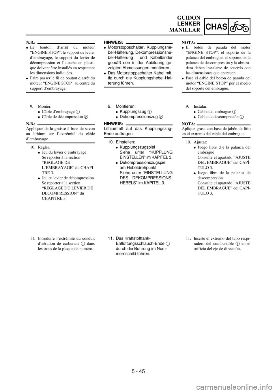
HINWEIS:
lMotorstoppschalter, Kupplungshe-
bel-Halterung, Dekompressionshe-
bel-Halterung und Kabelbinder
gemäß den in der Abbildung ge-
zeigten Abmessungen montieren.
lDas Motorstoppschalter-Kabel mit-
tig durch die Kupplungshebel-Hal-
terung führen.
9. Montieren:
lKupplungszug 1
lDekompressionszug 2
HINWEIS:
Lithiumfett auf das Kupplungszug-
Ende auftragen.
10. Einstellen:
lKupplungszugspiel
Siehe unter “KUPPLUNG
EINSTELLEN” im KAPITEL 3.
lDekompressionszugspiel
am Hebeldrehpunkt
Siehe unter “EINSTELLUNG
DES DEKOMPRESSIONS-
HEBELS” im KAPITEL 3.
11. Das Kraftstofftank-
Entlüftungsschlauch-Ende 1
durch die Bohrung im Num-
mernschild führen.
N.B.:
lLe bouton d’arrêt du moteur
“ENGINE STOP”, le support de levier
d’embrayage, le support du levier de
décompression et l’attache en plasti-
que doivent être installés en respectant
les dimensions indiquées.
lFaire passer le fil de bouton d’arrêt du
moteur “ENGINE STOP” au centre du
support d’embrayage.
9. Monter:
lCâble d’embrayage 1
lCâble de décompression 2
N.B.:
Appliquer de la graisse à base de savon
au lithium sur l’extrémité du câble
d’embrayage.
10. Régler:
lJeu du levier d’embrayage
Se reporter à la section
“REGLAGE DE
L’EMBRAYAGE” du CHAPI-
TRE 3.
lJeu au levier de décompression
Se reporter à la section
“REGLAGE DU LEVIER DE
DECOMPRESSION” du
CHAPITRE 3.
11. Introduire l’extrémité du conduit
d’aération de carburant 1 dans
les trous de la plaque de numéro.
NOTA:
lEl botón de parada del motor
“ENGINE STOP”, el soporte de la
palanca del embrague, el soporte de la
palanca de descompresión y la abraza-
dera deben instalarse de acuerdo con
las dimensiones que aparecen.
lPase el cable del botón de parada del
motor “ENGINE STOP” por el medio
del soporte del embrague.
9. Instalar:
lCable del embrague 1
lCable de descompresión 2
NOTA:
Aplique grasa con base de jabón de litio
en el extremo del cable del embrague.
10. Ajustar:
lJuego libre d e la palanca del
embrague
Consulte el apartado “AJUSTE
DEL EMBRAGUE” del CAPÍ-
TULO 3.
lJuego libre de la palanca de
descompresión
Consulte el apartado “AJUSTE
DEL EMBRAGUE” del CAPÍ-
TULO 3.
11. Inserte el extremo del tubo respi-
radero del combustible 1 en el
orificio del eje de dirección.
Page 636 of 762
5 - 46
CHAS
EC560000
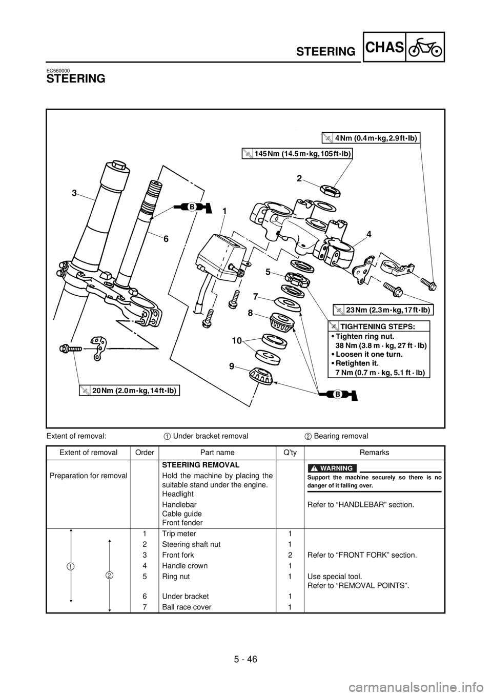
STEERING
Extent of removal:1 Under bracket removal2 Bearing removal
Extent of removal Order Part name Q’ty Remarks
STEERING REMOVAL
WARNING
Support the machine securely so there is nodanger of it falling over.
Preparation for removal Hold the machine by placing the
suitable stand under the engine.
Headlight
Handlebar
Cable guide
Front fenderRefer to “HANDLEBAR” section.
1 Trip meter 1
2 Steering shaft nut 1
3 Front fork 2 Refer to “FRONT FORK” section.
4 Handle crown 1
5 Ring nut 1 Use special tool.
Refer to “REMOVAL POINTS”.
6 Under bracket 1
7Ball race cover
1
2
1
STEERING
Page 637 of 762
5 - 46
CHAS
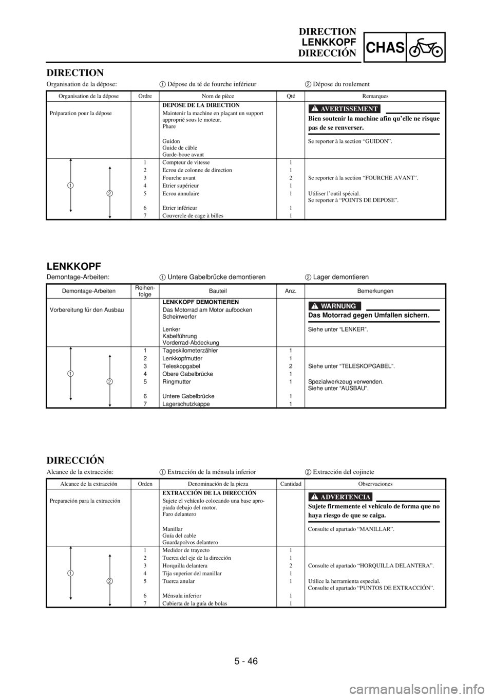
LENKKOPF
Demontage-Arbeiten:1 Untere Gabelbrücke demontieren2 Lager demontieren
Demontage-ArbeitenReihen-
folgeBauteil Anz. Bemerkungen
LENKKOPF DEMONTIEREN
Vorbereitung für den Ausbau Das Motorrad am Motor aufbocken
Scheinwerfer
Lenker
Kabelführung
Vorderrad-AbdeckungSiehe unter “LENKER”.
1 Tageskilometerzähler 1
2 Lenkkopfmutter 1
3 Teleskopgabel 2 Siehe unter “TELESKOPGABEL”.
4 Obere Gabelbrücke 1
5 Ringmutter 1 Spezialwerkzeug verwenden.
Siehe unter “AUSBAU”.
6 Untere Gabelbrücke 1
7 Lagerschutzkappe 1
WARNUNG
Das Motorrad gegen Umfallen sichern.
12
DIRECTION
LENKKOPF
DIRECCIÓN
DIRECTION
Organisation de la dépose:1 Dépose du té de fourche inférieur2 Dépose du roulement
Organisation de la dépose Ordre Nom de pièce Qté Remarques
DEPOSE DE LA DIRECTION
Préparation pour la dépose Maintenir la machine en plaçant un support
approprié sous le moteur.
Phare
Guidon
Guide de câble
Garde-boue avantSe reporter à la section “GUIDON”.
1 Compteur de vitesse 1
2 Ecrou de colonne de direction 1
3 Fourche avant 2 Se reporter à la section “FOURCHE AVANT”.
4 Etrier supérieur 1
5 Ecrou annulaire 1 Utiliser l’outil spécial.
Se reporter à “POINTS DE DEPOSE”.
6 Etrier inférieur 1
7 Couvercle de cage à billes 1
AVERTISSEMENT
Bien soutenir la machine afin qu’elle ne risque
pas de se renverser.
12
DIRECCIÓN
Alcance de la extracción:1 Extracción de la ménsula inferior2 Extracción del cojinete
Alcance de la extracción Orden Denominación de la pieza Cantidad Observaciones
EXTRACCIÓN DE LA DIRECCIÓN
Preparación para la extracción Sujete el vehículo colocando una base apro-
piada debajo del motor.
Faro delantero
Manillar
Guía del cable
Guardapolvos delanteroConsulte el apartado “MANILLAR”.
1 Medidor de trayecto 1
2 Tuerca del eje de la dirección 1
3 Horquilla delantera 2 Consulte el apartado “HORQUILLA DELANTERA”.
4 Tija superior del manillar 1
5 Tuerca anular 1 Utilice la herramienta especial.
Consulte el apartado “PUNTOS DE EXTRACCIÓN”.
6 Ménsula inferior 1
7 Cubierta de la guía de bolas 1
ADVERTENCIA
Sujete firmemente el vehículo de forma que no
haya riesgo de que se caiga.
12
Page 638 of 762
5 - 47
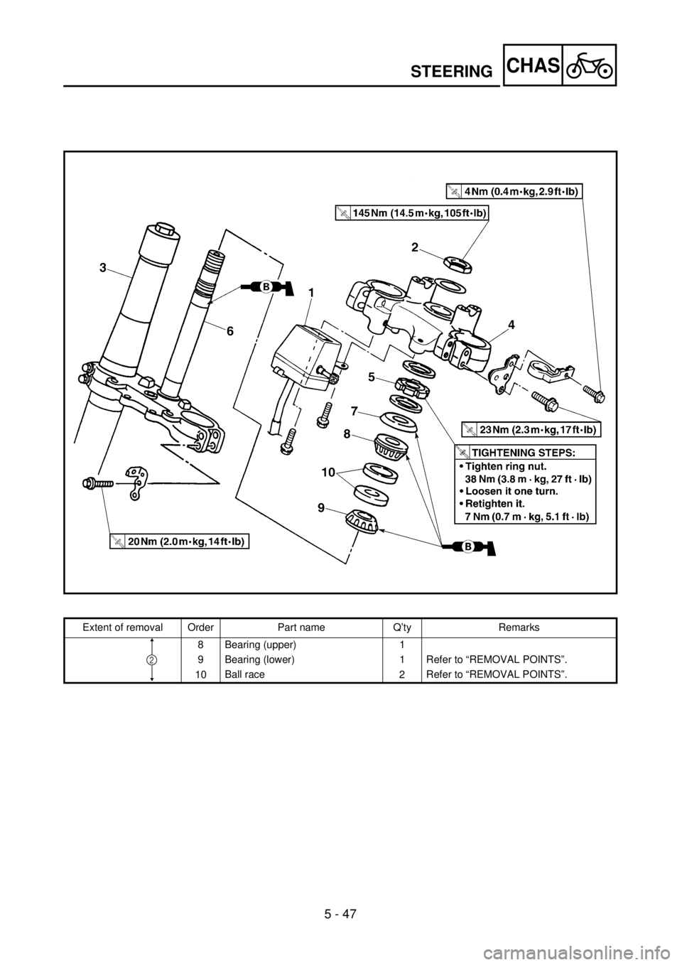
CHASSTEERING
Extent of removal Order Part name Q’ty Remarks
8 Bearing (upper) 1
9 Bearing (lower) 1 Refer to “REMOVAL POINTS”.
10Ball race
2Refer to “REMOVAL POINTS”.
2
Page 639 of 762
5 - 47
CHAS
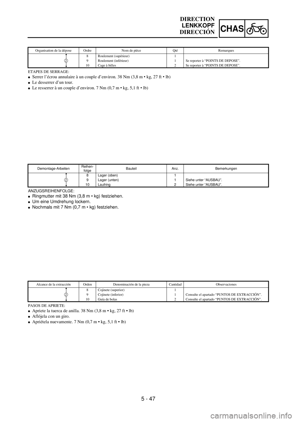
ETAPES DE SERRAGE:
lSerrer l’écrou annulaire à un couple d’environ. 38 Nm (3,8 m • kg, 27 ft • lb)
lLe desserrer d’un tour.
lLe resserrer à un couple d’environ. 7 Nm (0,7 m • kg, 5,1 ft • lb)
Organisation de la dépose Ordre Nom de pièce Qté Remarques
8 Roulement (supérieur) 1
9 Roulement (inférieur) 1 Se reporter à “POINTS DE DEPOSE”.
10 Cage à billes 2 Se reporter à “POINTS DE DEPOSE”.
2
ANZUGSREIHENFOLGE:
lRingmutter mit 38 Nm (3,8 m • kg) festziehen.
lUm eine Umdrehung lockern.
lNochmals mit 7 Nm (0,7 m • kg) festziehen.
Demontage-ArbeitenReihen-
folgeBauteil Anz. Bemerkungen
8 Lager (oben) 1
9 Lager (unten) 1 Siehe unter “AUSBAU”.
10 Laufring 2 Siehe unter “AUSBAU”.
2
PASOS DE APRIETE:
lApriete la tuerca de anilla. 38 Nm (3,8 m • kg, 27 ft • lb)
lAflójela con un giro.
lApriétela nuevamente. 7 Nm (0,7 m • kg, 5,1 ft • lb)
Alcance de la extracción Orden Denominación de la pieza Cantidad Observaciones
8 Cojinete (superior) 1
9 Cojinete (inferior) 1 Consulte el apartado “PUNTOS DE EXTRACCIÓN”.
10 Guía de bolas 2 Consulte el apartado “PUNTOS DE EXTRACCIÓN”.
2
DIRECTION
LENKKOPF
DIRECCIÓN
Page 640 of 762
5 - 48
CHAS
EC563000
REMOVAL POINTS
EC563202
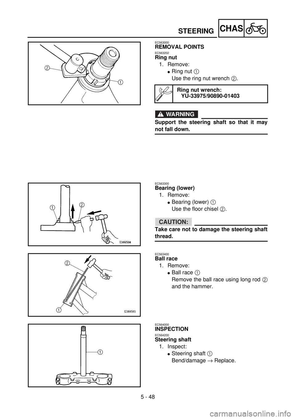
Ring nut
1. Remove:
lRing nut 1
Use the ring nut wrench 2.
WARNING
Support the steering shaft so that it may
not fall down.
Ring nut wrench:
YU-33975/90890-01403
EC563300
Bearing (lower)
1. Remove:
lBearing (lower) 1
Use the floor chisel 2.
CAUTION:
Take care not to damage the steering shaft
thread.
EC563400
Ball race
1. Remove:
lBall race 1
Remove the ball race using long rod 2
and the hammer.
EC564000
INSPECTION
EC564200
Steering shaft
1. Inspect:
lSteering shaft 1
Bend/damage ® Replace.
STEERING