coolant YAMAHA WR 400F 2001 Owners Manual
[x] Cancel search | Manufacturer: YAMAHA, Model Year: 2001, Model line: WR 400F, Model: YAMAHA WR 400F 2001Pages: 762, PDF Size: 62.36 MB
Page 26 of 762
1 - 1
GEN
INFO
DESCRIPTION
EC100000
GENERAL INFORMATION
EC110000
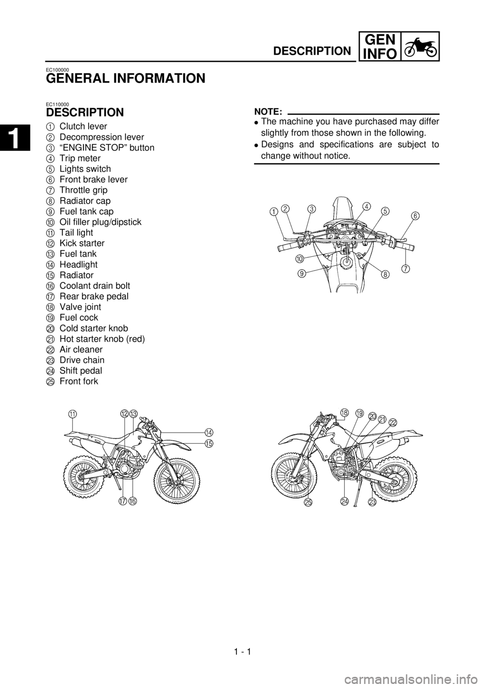
DESCRIPTION
1
Clutch lever
2
Decompression lever
3
“ENGINE STOP” button
4
Trip meter
5
Lights switch
6
Front brake lever
7
Throttle grip
8
Radiator cap
9
Fuel tank cap
0
Oil filler plug/dipstick
A
Tail light
B
Kick starter
C
Fuel tank
D
Headlight
E
Radiator
F
Coolant drain bolt
G
Rear brake pedal
H
Valve joint
I
Fuel cock
J
Cold starter knob
K
Hot starter knob (red)
L
Air cleaner
M
Drive chain
N
Shift pedal
O
Front fork
NOTE:
l
The machine you have purchased may differ
slightly from those shown in the following.
l
Designs and specifications are subject to
change without notice.
1
1
Page 58 of 762
1 - 14
GEN
INFO
STARTING AND BREAK-IN
STARTING AND BREAK-IN
WARNING
Never start or run the engine in a closed
area. The exhaust fumes are poisonous;
they can cause loss of consciousness and
death in a very short time. Always operate
the machine in a well-ventilated area.
CAUTION:
lThe carburetor on this motorcycle has a
built-in accelerator pump. Therefore,
when starting the engine, do not operate
the throttle or the spark plug will foul.
lUnlike a two-stroke engine, this engine
cannot be kick started when the throttle is
open because the kick starter may kick
back. Also, if the throttle is open the air/
fuel mixture may be too lean for the
engine to start.
lNever use the decompression lever after
the engine is started. The engine may be
damaged if you use the decompression
lever while it is running.
lBefore starting the machine, perform the
checks in the pre-operation check list.
STARTING A COLD ENGINE
1. Inspect the coolant level.
2. Turn the fuel cock to “ON”.
3. Shift the transmission into neutral.
4. Fully open the cold starter knob.
5. Without pulling in the decompression
lever, slowly depress the kick starter until
the compression stroke is found. When
considerable resistance of the kick starter
is felt, the engine is on the compression
stroke. If the engine is on the exhaust
stroke, resistance will only be felt when
the kick starter is initially depressed, not
through the entire range of depression
(as when the engine is on the compres-
sion stroke); therefore, depress the kick
starter a few more times.
Page 75 of 762

2 - 2
SPEC
GENERAL SPECIFICATIONS (WR426F)
Oil capacity:
Engine oil
Periodic oil change 1.5 L (1.32 Imp qt, 1.59 US qt)
With oil filter replacement 1.6 L (1.41 Imp qt, 1.69 US qt)
Total amount 1.7 L (1.50 Imp qt, 1.80 US qt)
Coolant capacity (including all routes): 1.2 L (1.06 Imp qt, 1.27 US qt)
Air filter: Wet type element
Fuel:
Type Premium unleaded fuel with a research octane
number of 95 or higher. (Except for AUS)
Unleaded fuel only (For AUS)
Tank capacity 12 L (2.64 Imp gal, 3.17 US gal)
(For USA, CDN)
8.0 L (1.76 Imp gal, 2.11 US gal)
(Except for USA, CDN)
Reserve 1.6 L (0.35 Imp gal, 0.42 US gal)
(For USA, CDN)
1.4 L (0.31 Imp gal, 0.37 US gal)
(Except for USA, CDN)
Carburetor:
Type FCR-MX39
Manufacturer KEIHIN
Spark plug:
Type/manufacturer CR8E/NGK
U24ESR-N/DENSO
Gap 0.7 ~ 0.8 mm (0.028 ~ 0.031 in)
Clutch type: Wet, multiple-disc
Transmission:
Primary reduction system Gear
Primary reduction ratio 62/21 (2.952)
Secondary reduction system Chain drive
Secondary reduction ratio 50/14 (3.571)
Transmission type Constant mesh, 5-speed
Operation Left foot operation
Gear ratio: 1st 29/12 (2.416)
2nd 26/15 (1.733)
3rd 21/16 (1.312)
4th 21/20 (1.050)
5th 21/25 (0.840)
Chassis:
Frame type Semi double cradle
Caster angle 27.8˚
Trail 123 mm (4.84 in)
2
Page 84 of 762

2 - 11
SPEC
MAINTENANCE SPECIFICATIONS (WR426F)
Part to be tightened Thread size Q’tyTightening torque
Nm m·kg ft·lb
Spark plug M10S
´
1.0 1 13 1.3 9.4
Camshaft cap M6
´
1.0 10 10 1.0 7.2
Cylinder head (stud bolt) M6
´
1.0 2 7 0.7 5.1
M8
´
1.25 3 15 1.5 11
(bolt) M10
´
1.25 4 44 4.4 32
(nut) M6
´
1.0 2 10 1.0 7.2
M8
´
1.25 2 20 2.0 14
Cylinder head cover M6
´
1.0 2 10 1.0 7.2
Cylinder M6
´
1.0 1 10 1.0 7.2
Timing chain tensioner M6
´
1.0 2 10 1.0 7.2
Tensioner cap bolt M6
´
1.0 1 7 0.7 5.1
Timing chain guide (rear) M6
´
1.0 2 10 1.0 7.2
Decompression shaft M6
´
1.0 1 7 0.7 5.1
Decompression cable guide M6
´
1.0 1 10 1.0 7.2
Exhaust pipe (nut) M8
´
1.25 1 13 1.3 9.4
(bolt) M8
´
1.25 1 24 2.4 17
Silencer M8
´
1.25 2 35 3.5 25
Silencer clamp M8
´
1.25 1 20 2.0 14
Exhaust pipe protector M6
´
1.0 3 10 1.0 7.2
Spark arrester (for USA) M6
´
1.0 3 10 1.0 7.2
Silencer end pipe (for USA) M6
´
1.0 1 10 1.0 7.2
Clamp (air cleaner joint) M5
´
0.8 1 3 0.3 2.2
Clamp (carburetor joint) M4
´
0.7 1 3 0.3 2.2
Air filter joint clamp M6
´
1.0 1 3 0.3 2.2
Throttle cable cover M5
´
0.8 1 4 0.4 2.9
Air filter element M6
´
1.0 1 2 0.2 1.4
Air filter case cover M6
´
1.0 4 4 0.4 2.9
Radiator panel (upper) M6
´
1.0 2 10 1.0 7.2
Radiator M6
´
1.0 6 10 1.0 7.2
Radiator hose clamp M6
´
1.0 8 2 0.2 1.4
Impeller M8
´
1.25 1 14 1.4 10
Water pump housing cover M6
´ 1.0 3 10 1.0 7.2
Coolant drain bolt M6 ´ 1.0 1 10 1.0 7.2
Oil pump cover M5 ´ 0.8 1 4 0.4 2.9
Oil pump M6 ´ 1.0 3 10 1.0 7.2
Engine oil drain bolt (oil filter) M6 ´ 1.0 1 10 1.0 7.2
Oil filter cover M6 ´ 1.0 2 10 1.0 7.2
Oil delivery pipe 1 M10 ´ 1.25
M8 ´ 1.251
220
182.0
1.814
13
Oil hose clamp — 2 2 0.2 1.4
Clutch cover M6 ´ 1.0 7 10 1.0 7.2
Crankcase cover (right) M6 ´ 1.0 10 10 1.0 7.2
Crankcase cover (left) M6 ´ 1.0 8 10 1.0 7.2
Crankcase M6 ´ 1.0 12 12 1.2 8.7
Page 89 of 762
2 - 16
SPECMAINTENANCE SPECIFICATIONS (WR426F)
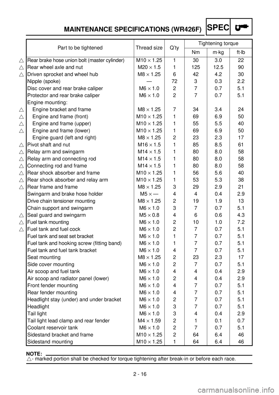
NOTE:
- marked portion shall be checked for torque tightening after break-in or before each race.Part to be tightened Thread size Q’tyTightening torque
Nm m·kg ft·lb
Rear brake hose union bolt (master cylinder)M10 ´ 1.25 1 30 3.0 22
Rear wheel axle and nut M20 ´ 1.5 1 125 12.5 90
Driven sprocket and wheel hub M8 ´ 1.25 6 42 4.2 30
Nipple (spoke) — 72 3 0.3 2.2
Disc cover and rear brake caliper M6 ´ 1.0 2 7 0.7 5.1
Protector and rear brake caliper M6 ´ 1.0 2 7 0.7 5.1
Engine mounting:
Engine bracket and frame M8 ´ 1.25 7 34 3.4 24
Engine and frame (front) M10 ´ 1.25 1 69 6.9 50
Engine and frame (upper) M10 ´ 1.25 1 55 5.5 40
Engine and frame (lower) M10 ´ 1.25 1 69 6.9 50
Engine guard (left and right) M8 ´ 1.25 2 23 2.3 17
Pivot shaft and nut M16 ´ 1.5 1 85 8.5 61
Relay arm and swingarm M14 ´ 1.5 1 80 8.0 58
Relay arm and connecting rod M14 ´ 1.5 1 80 8.0 58
Connecting rod and frame M14 ´ 1.5 1 80 8.0 58
Rear shock absorber and frame M10 ´ 1.25 1 56 5.6 40
Rear shock absorber and relay arm M10 ´ 1.25 1 53 5.3 38
Rear frame and frame M8 ´ 1.25 3 29 2.9 21
Swingarm and brake hose holder M5 ´ — 4 4 0.4 2.9
Drive chain tensioner mounting M8 ´ 1.25 2 19 1.9 13
Chain support and swingarm M6 ´ 1.0 3 7 0.7 5.1
Seal guard and swingarm M5 ´ 0.8 4 6 0.6 4.3
Fuel tank mounting M6 ´ 1.0 2 10 1.0 7.2
Fuel tank and fuel cock M6 ´ 1.0 2 7 0.7 5.1
Fuel tank and seat set bracket M6 ´ 1.0 1 7 0.7 5.1
Fuel tank and hooking screw (fitting band) M6 ´ 1.0 1 7 0.7 5.1
Fuel tank and fuel tank bracket M6 ´ 1.0 4 7 0.7 5.1
Seat mounting M8 ´ 1.25 2 23 2.3 17
Side cover mounting M6 ´ 1.0 2 7 0.7 5.1
Air scoop and fuel tank M6 ´ 1.0 4 4 0.4 2.9
Air scoop and radiator panel (lower) M6 ´ 1.0 2 4 0.4 2.9
Front fender mounting M6 ´ 1.0 4 7 0.7 5.1
Rear fender mounting M6 ´ 1.0 4 7 0.7 5.1
Headlight stay (under) and under bracket M6 ´ 1.0 2 7 0.7 5.1
Headlight M6 ´ 1.0 3 7 0.7 5.1
Tail light M6 ´ 1.0 3 4 0.4 2.9
Tail light lead clamp and rear fender M4 ´ 1.59 2 1 0.1 0.7
Coolant reservoir tank M6 ´ 1.0 2 7 0.7 5.1
Sidestand bracket and frame M10 ´ 1.25 2 64 6.4 46
Sidestand mounting M10 ´ 1.25 1 64 6.4 46
Page 91 of 762
2 - 18
SPECGENERAL SPECIFICATIONS (WR400F)
EC211000
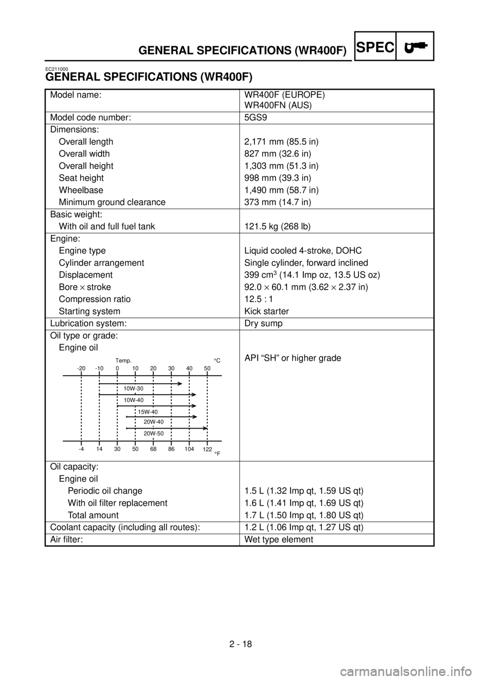
GENERAL SPECIFICATIONS (WR400F)
Model name: WR400F (EUROPE)
WR400FN (AUS)
Model code number: 5GS9
Dimensions:
Overall length 2,171 mm (85.5 in)
Overall width 827 mm (32.6 in)
Overall height 1,303 mm (51.3 in)
Seat height 998 mm (39.3 in)
Wheelbase 1,490 mm (58.7 in)
Minimum ground clearance 373 mm (14.7 in)
Basic weight:
With oil and full fuel tank 121.5 kg (268 lb)
Engine:
Engine type Liquid cooled 4-stroke, DOHC
Cylinder arrangement Single cylinder, forward inclined
Displacement 399 cm
3 (14.1 Imp oz, 13.5 US oz)
Bore ´ stroke 92.0 ´ 60.1 mm (3.62 ´ 2.37 in)
Compression ratio 12.5 : 1
Starting system Kick starter
Lubrication system: Dry sump
Oil type or grade:
Engine oil
API “SH” or higher grade
Oil capacity:
Engine oil
Periodic oil change 1.5 L (1.32 Imp qt, 1.59 US qt)
With oil filter replacement 1.6 L (1.41 Imp qt, 1.69 US qt)
Total amount 1.7 L (1.50 Imp qt, 1.80 US qt)
Coolant capacity (including all routes): 1.2 L (1.06 Imp qt, 1.27 US qt)
Air filter: Wet type element
-20
-4-10
140
3010
5020
6830
8640 50
104
122¡CTemp.
¡F
10W-30
10W-40
20W-40
20W-50
15W-40
Page 101 of 762

2 - 28
SPECMAINTENANCE SPECIFICATIONS (WR400F)
Part to be tightened Thread size Q’tyTightening torque
Nm m·kg ft·lb
Spark plug M10S ´ 1.0 1 13 1.3 9.4
Camshaft cap M6 ´ 1.0 10 10 1.0 7.2
Cylinder head (stud bolt) M6 ´ 1.0 2 7 0.7 5.1
M8 ´ 1.25 3 15 1.5 11
(bolt) M10 ´ 1.25 4 44 4.4 32
(nut) M6 ´ 1.0 2 10 1.0 7.2
M8 ´ 1.25 2 20 2.0 14
Cylinder head cover M6 ´ 1.0 2 10 1.0 7.2
Cylinder M6 ´ 1.0 1 10 1.0 7.2
Timing chain tensioner M6 ´ 1.0 2 10 1.0 7.2
Tensioner cap bolt M6 ´ 1.0 1 7 0.7 5.1
Timing chain guide (rear) M6 ´ 1.0 2 10 1.0 7.2
Decompression shaft M6 ´ 1.0 1 7 0.7 5.1
Decompression cable guide M6 ´ 1.0 1 10 1.0 7.2
Exhaust pipe (nut) M8 ´ 1.25 1 13 1.3 9.4
(bolt) M8 ´ 1.25 1 24 2.4 17
Silencer M8 ´ 1.25 2 35 3.5 25
Silencer clamp M8 ´ 1.25 1 20 2.0 14
Exhaust pipe protector M6 ´ 1.0 3 10 1.0 7.2
Spark arrester (for USA) M6 ´ 1.0 3 10 1.0 7.2
Silencer end pipe (for USA) M6 ´ 1.0 1 10 1.0 7.2
Clamp (air cleaner joint) M5 ´ 0.8 1 3 0.3 2.2
Clamp (carburetor joint) M4 ´ 0.7 1 3 0.3 2.2
Air filter joint clamp M6 ´ 1.0 1 3 0.3 2.2
Throttle cable cover M5 ´ 0.8 1 4 0.4 2.9
Air filter element M6 ´ 1.0 1 2 0.2 1.4
Air filter case cover M6 ´ 1.0 4 4 0.4 2.9
Radiator panel (upper) M6 ´ 1.0 2 10 1.0 7.2
Radiator M6 ´ 1.0 6 10 1.0 7.2
Radiator hose clamp M6 ´ 1.0 8 2 0.2 1.4
Impeller M8 ´ 1.25 1 14 1.4 10
Water pump housing cover M6 ´ 1.0 3 10 1.0 7.2
Coolant drain bolt M6 ´ 1.0 1 10 1.0 7.2
Oil pump cover M5 ´ 0.8 1 4 0.4 2.9
Oil pump M6 ´ 1.0 3 10 1.0 7.2
Engine oil drain bolt (oil filter) M6 ´ 1.0 1 10 1.0 7.2
Oil filter cover M6 ´ 1.0 2 10 1.0 7.2
Oil delivery pipe 1 M10 ´ 1.25
M8 ´ 1.251
220
182.0
1.814
13
Oil hose clamp — 2 2 0.2 1.4
Clutch cover M6 ´ 1.0 7 10 1.0 7.2
Crankcase cover (right) M6 ´ 1.0 10 10 1.0 7.2
Crankcase cover (left) M6 ´ 1.0 8 10 1.0 7.2
Crankcase M6 ´ 1.0 12 12 1.2 8.7
Page 106 of 762
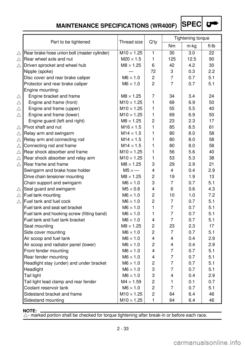
2 - 33
SPECMAINTENANCE SPECIFICATIONS (WR400F)
NOTE:
- marked portion shall be checked for torque tightening after break-in or before each race.Part to be tightened Thread size Q’tyTightening torque
Nm m·kg ft·lb
Rear brake hose union bolt (master cylinder)M10 ´ 1.25 1 30 3.0 22
Rear wheel axle and nut M20 ´ 1.5 1 125 12.5 90
Driven sprocket and wheel hub M8 ´ 1.25 6 42 4.2 30
Nipple (spoke) — 72 3 0.3 2.2
Disc cover and rear brake caliper M6 ´ 1.0 2 7 0.7 5.1
Protector and rear brake caliper M6 ´ 1.0 2 7 0.7 5.1
Engine mounting:
Engine bracket and frame M8 ´ 1.25 7 34 3.4 24
Engine and frame (front) M10 ´ 1.25 1 69 6.9 50
Engine and frame (upper) M10 ´ 1.25 1 55 5.5 40
Engine and frame (lower) M10 ´ 1.25 1 69 6.9 50
Engine guard (left and right) M8 ´ 1.25 2 23 2.3 17
Pivot shaft and nut M16 ´ 1.5 1 85 8.5 61
Relay arm and swingarm M14 ´ 1.5 1 80 8.0 58
Relay arm and connecting rod M14 ´ 1.5 1 80 8.0 58
Connecting rod and frame M14 ´ 1.5 1 80 8.0 58
Rear shock absorber and frame M10 ´ 1.25 1 56 5.6 40
Rear shock absorber and relay arm M10 ´ 1.25 1 53 5.3 38
Rear frame and frame M8 ´ 1.25 3 29 2.9 21
Swingarm and brake hose holder M5 ´ — 4 4 0.4 2.9
Drive chain tensioner mounting M8 ´ 1.25 2 19 1.9 13
Chain support and swingarm M6 ´ 1.0 3 7 0.7 5.1
Seal guard and swingarm M5 ´ 0.8 4 6 0.6 4.3
Fuel tank mounting M6 ´ 1.0 2 10 1.0 7.2
Fuel tank and fuel cock M6 ´ 1.0 2 7 0.7 5.1
Fuel tank and seat set bracket M6 ´ 1.0 1 7 0.7 5.1
Fuel tank and hooking screw (fitting band) M6 ´ 1.0 1 7 0.7 5.1
Fuel tank and fuel tank bracket M6 ´ 1.0 4 7 0.7 5.1
Seat mounting M8 ´ 1.25 2 23 2.3 17
Side cover mounting M6 ´ 1.0 2 7 0.7 5.1
Air scoop and fuel tank M6 ´ 1.0 4 4 0.4 2.9
Air scoop and radiator panel (lower) M6 ´ 1.0 2 4 0.4 2.9
Front fender mounting M6 ´ 1.0 4 7 0.7 5.1
Rear fender mounting M6 ´ 1.0 4 7 0.7 5.1
Headlight stay (under) and under bracket M6 ´ 1.0 2 7 0.7 5.1
Headlight M6 ´ 1.0 3 7 0.7 5.1
Tail light M6 ´ 1.0 3 4 0.4 2.9
Tail light lead clamp and rear fender M4 ´ 1.59 2 1 0.1 0.7
Coolant reservoir tank M6 ´ 1.0 2 7 0.7 5.1
Sidestand bracket and frame M10 ´ 1.25 2 64 6.4 46
Sidestand mounting M10 ´ 1.25 1 64 6.4 46
Page 218 of 762
2 - 38
SPEC
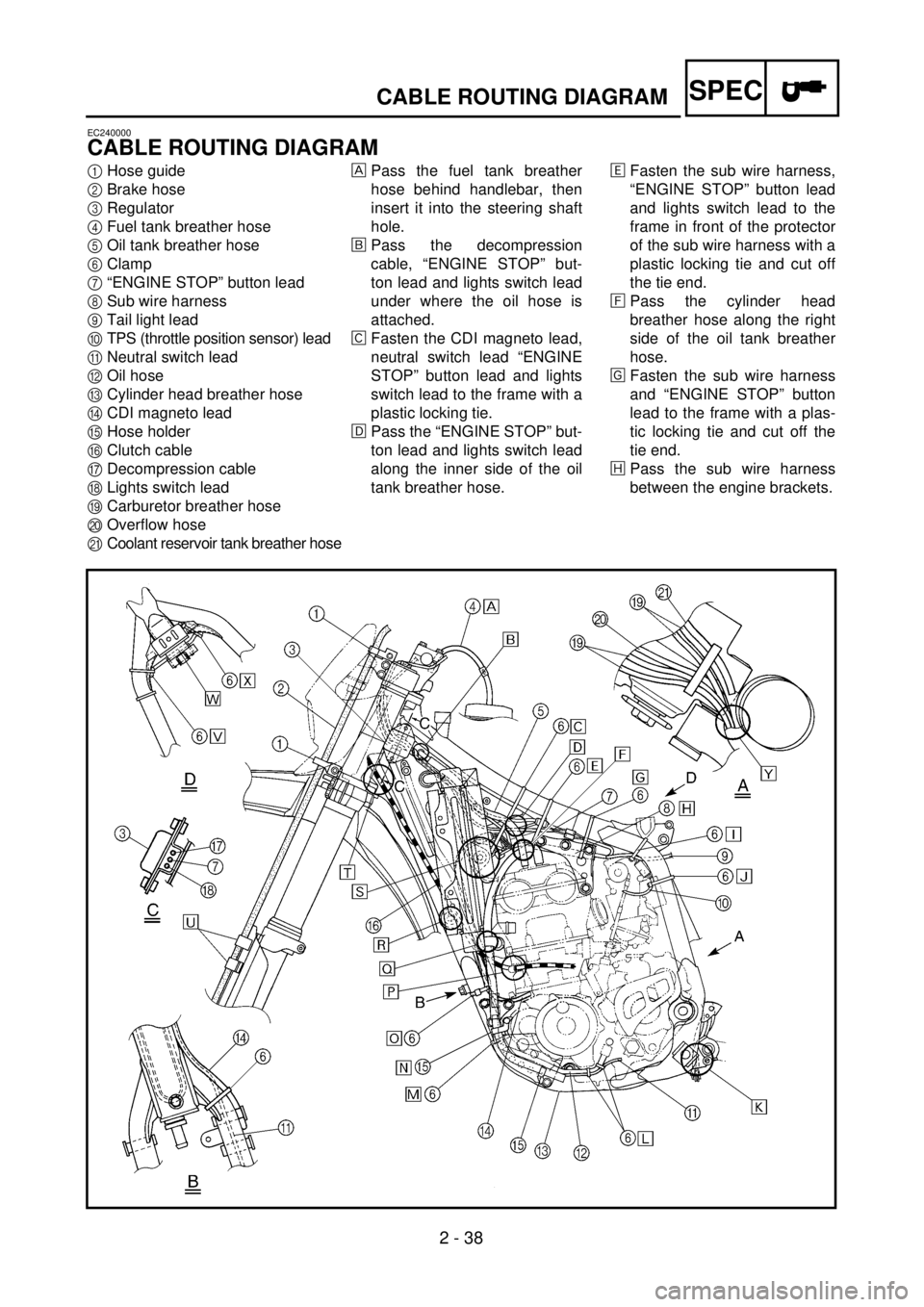
CABLE ROUTING DIAGRAM
EC240000
CABLE ROUTING DIAGRAM
1
Hose guide
2
Brake hose
3
Regulator
4
Fuel tank breather hose
5
Oil tank breather hose
6
Clamp
7
“ENGINE STOP” button lead
8
Sub wire harness
9
Tail light lead
0
TPS (throttle position sensor) lead
A
Neutral switch lead
B
Oil hose
C
Cylinder head breather hose
D
CDI magneto lead
E
Hose holder
F
Clutch cable
G
Decompression cable
H
Lights switch lead
I
Carburetor breather hose
J
Overflow hose
K
Coolant reservoir tank breather hose
Pass the fuel tank breather
hose behind handlebar, then
insert it into the steering shaft
hole.
õ
Pass the decompression
cable, “ENGINE STOP” but-
ton lead and lights switch lead
under where the oil hose is
attached.
‚
Fasten the CDI magneto lead,
neutral switch lead “ENGINE
STOP” button lead and lights
switch lead to the frame with a
plastic locking tie.
ë
Pass the “ENGINE STOP” but-
ton lead and lights switch lead
along the inner side of the oil
tank breather hose.
ä
Fasten the sub wire harness,
“ENGINE STOP” button lead
and lights switch lead to the
frame in front of the protector
of the sub wire harness with a
plastic locking tie and cut off
the tie end.
ì
Pass the cylinder head
breather hose along the right
side of the oil tank breather
hose.
í
Fasten the sub wire harness
and “ENGINE STOP” button
lead to the frame with a plas-
tic locking tie and cut off the
tie end.
î
Pass the sub wire harness
between the engine brackets.
Page 222 of 762
2 - 40
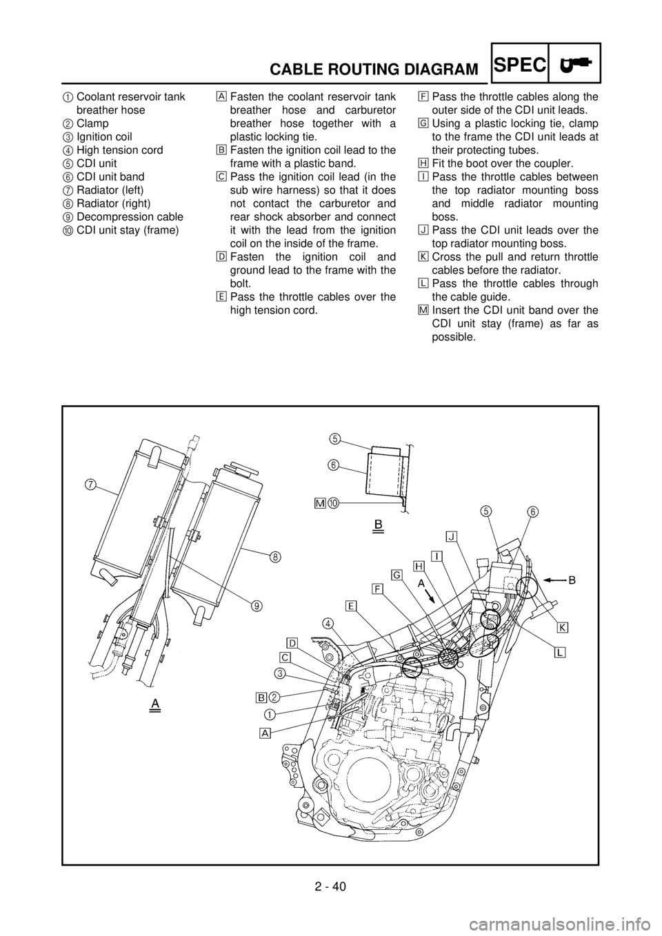
SPECCABLE ROUTING DIAGRAM
1Coolant reservoir tank
breather hose
2Clamp
3Ignition coil
4High tension cord
5CDI unit
6CDI unit band
7Radiator (left)
8Radiator (right)
9Decompression cable
0CDI unit stay (frame)Fasten the coolant reservoir tank
breather hose and carburetor
breather hose together with a
plastic locking tie.
õFasten the ignition coil lead to the
frame with a plastic band.
‚Pass the ignition coil lead (in the
sub wire harness) so that it does
not contact the carburetor and
rear shock absorber and connect
it with the lead from the ignition
coil on the inside of the frame.
ëFasten the ignition coil and
ground lead to the frame with the
bolt.
äPass the throttle cables over the
high tension cord.ìPass the throttle cables along the
outer side of the CDI unit leads.
íUsing a plastic locking tie, clamp
to the frame the CDI unit leads at
their protecting tubes.
îFit the boot over the coupler.
éPass the throttle cables between
the top radiator mounting boss
and middle radiator mounting
boss.
ïPass the CDI unit leads over the
top radiator mounting boss.
ðCross the pull and return throttle
cables before the radiator.
ñPass the throttle cables through
the cable guide.
÷Insert the CDI unit band over the
CDI unit stay (frame) as far as
possible.