diagram YAMAHA WR 426F 2001 User Guide
[x] Cancel search | Manufacturer: YAMAHA, Model Year: 2001, Model line: WR 426F, Model: YAMAHA WR 426F 2001Pages: 762, PDF Size: 62.36 MB
Page 214 of 762
2 - 36
SPEC
LUBRICATION DIAGRAMS
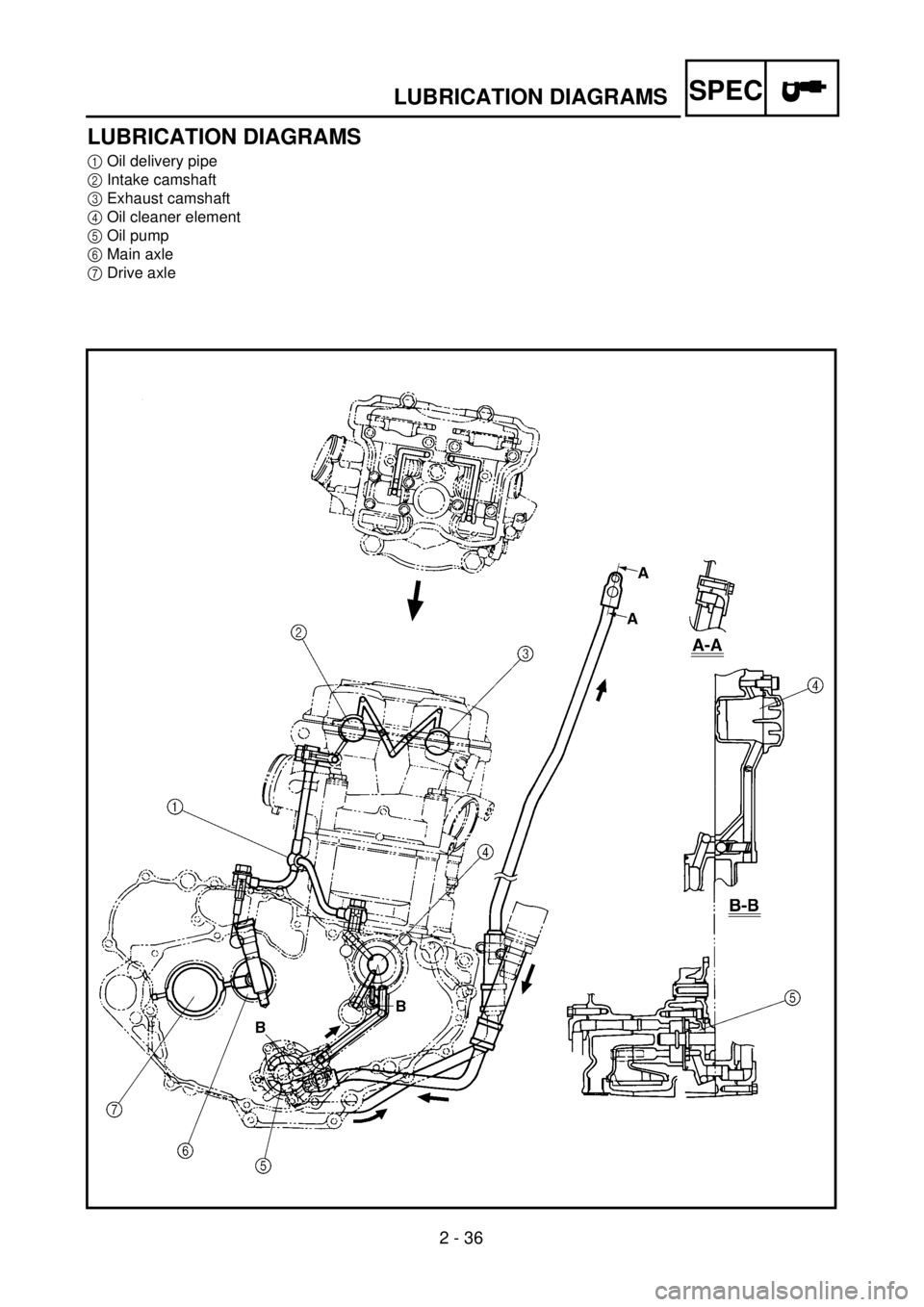
LUBRICATION DIAGRAMS
1
Oil delivery pipe
2
Intake camshaft
3
Exhaust camshaft
4
Oil cleaner element
5
Oil pump
6
Main axle
7
Drive axle
Page 215 of 762

SPEC
2 - 36
SCHEMAS DE GRAISSAGE
SCHMIERSYSTEM-SCHAUBILDER
DIAGRAMAS DE LUBRICACIÓN
SCHMIERSYSTEM-
SCHAUBILDER
1
Ölzufuhrleitung
2
Einlaß-Nockenwelle
3
Auslaß-Nockenwelle
4
Ölfiltereinsatz
5
Ölpumpe
6
Getriebe-Eingangswelle
7
Getriebe-Ausgangswelle
SCHEMAS DE GRAIS-
SAGE
1
Tuyau d’arrivée d’huile
2
Arbre à cames d’admission
3
Arbre à cames d’échappement
4
Element du filtre à air
5
Pompe à huile
6
Arbre primaire
7
Arbre secondaire
DIAGRAMAS DE LUBRI-
CACIÓN
1
Tubo de distribución del aceite
2
Admisión del árbol de levas
3
Escape del árbol de levas
4
Elemento del filtro de aceite
5
Bomba de aceite
6
Eje principal
7
Eje de salida
Page 216 of 762
2 - 37
SPEC
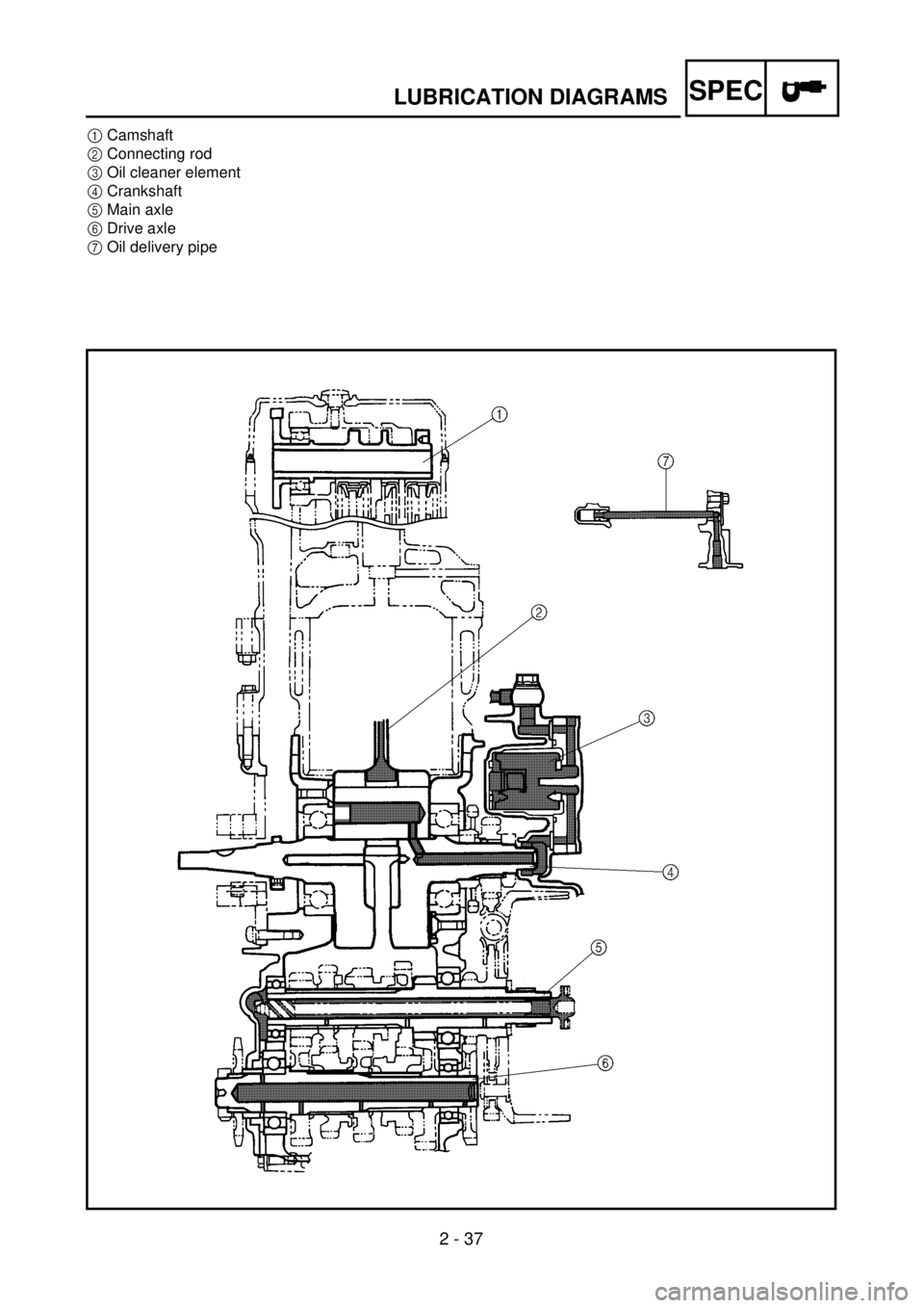
LUBRICATION DIAGRAMS
1
Camshaft
2
Connecting rod
3
Oil cleaner element
4
Crankshaft
5
Main axle
6
Drive axle
7
Oil delivery pipe
Page 217 of 762

SPEC
2 - 37
SCHEMAS DE GRAISSAGE
SCHMIERSYSTEM-SCHAUBILDER
DIAGRAMAS DE LUBRICACIÓN
1
Nockenwelle
2
Pleuel
3
Ölfiltereinsatz
4
Kurbelwelle
5
Getriebe-Eingangswelle
6
Getriebe-Ausgangswelle
7
Ölzufuhrleitung
1
Arbre à cames
2
Bielle
3
Element du filtre à air
4
Vilebrequin
5
Arbre primaire
6
Arbre secondaire
7
Tuyau d’arrivée d’huile
1
Árbol de levas
2
Biela
3
Elemento del filtro de aceite
4
Arbol de levas
5
Eje principal
6
Eje de salida
7
Tubo de distribución de aceite
Page 218 of 762
2 - 38
SPEC
CABLE ROUTING DIAGRAM
EC240000
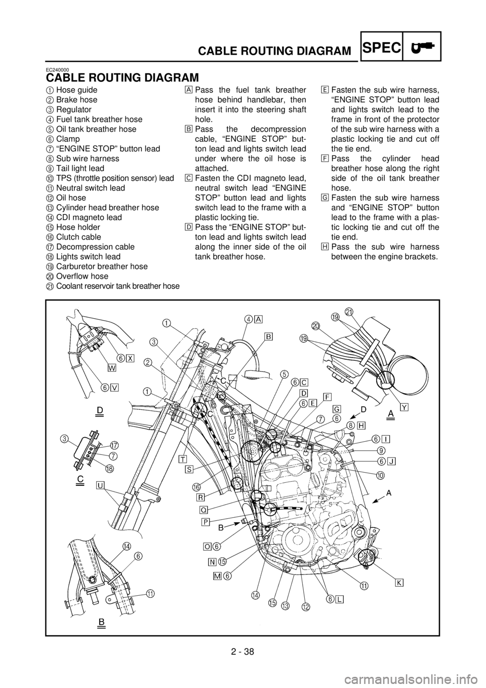
CABLE ROUTING DIAGRAM
1
Hose guide
2
Brake hose
3
Regulator
4
Fuel tank breather hose
5
Oil tank breather hose
6
Clamp
7
“ENGINE STOP” button lead
8
Sub wire harness
9
Tail light lead
0
TPS (throttle position sensor) lead
A
Neutral switch lead
B
Oil hose
C
Cylinder head breather hose
D
CDI magneto lead
E
Hose holder
F
Clutch cable
G
Decompression cable
H
Lights switch lead
I
Carburetor breather hose
J
Overflow hose
K
Coolant reservoir tank breather hose
Pass the fuel tank breather
hose behind handlebar, then
insert it into the steering shaft
hole.
õ
Pass the decompression
cable, “ENGINE STOP” but-
ton lead and lights switch lead
under where the oil hose is
attached.
‚
Fasten the CDI magneto lead,
neutral switch lead “ENGINE
STOP” button lead and lights
switch lead to the frame with a
plastic locking tie.
ë
Pass the “ENGINE STOP” but-
ton lead and lights switch lead
along the inner side of the oil
tank breather hose.
ä
Fasten the sub wire harness,
“ENGINE STOP” button lead
and lights switch lead to the
frame in front of the protector
of the sub wire harness with a
plastic locking tie and cut off
the tie end.
ì
Pass the cylinder head
breather hose along the right
side of the oil tank breather
hose.
í
Fasten the sub wire harness
and “ENGINE STOP” button
lead to the frame with a plas-
tic locking tie and cut off the
tie end.
î
Pass the sub wire harness
between the engine brackets.
Page 219 of 762

SPEC
2 - 38
CHEMINEMENT DES CABLES
KABELFÜHRUNG
DIAGRAMA DE RUTA DE CABLES
KABELFÜHRUNG
1
Kabelführung
2
Bremsschlauch
3
Regler
4
Kraftstofftank-Belüftungsschlauch
5
Öltank-Belüftungsschlauch
6
Kabelbinder
7
Motorstoppschalter-Kabel
8
Nebenkabelsatz
9
Rücklicht
0
Drosselklappensensor-Kabel
A
Leerlaufschalter-Kabel
BÖlschlauch
CZylinderkopf-Entlüftungsschlauch
DCDI-Schwungradmagnetzünder-Ka-
bel
ESchlauchhalterung
FKupplungszug
GDekompressionszug
HLichtschalterleitung
IVergaser-Entlüftungsschlauch
JAuslaufschutzschlauch
KKühlmittelausgleichstank-Lüftungs-
schlauch
Den Kraftstofftank-Belüftungs-
schlauch zwischen Lenker und
Zugstrebe führen und das Ende durch
die Bohrung im Nummerschild führen.
õDen Dekompressionszug hinter dem
Öltank-Belüftungsschlauch und über
das Öltankrohr führen.
‚Das CDI-Schwungradmagnetzünder-
Kabel, Leerlaufschalter-Kabel und
Motorstoppschalter-Kabel mit wieder-
verwenden. Kabelbinder am Rahmen
befestigen.
ëDas Motorstoppschalter-Kabel hinter
dem Öltank-Belüftungsschlauch füh-
ren.
äDen Nebenkabelbaum das Motor-
stoppschalter-Kabel und das Licht-
schalterkabel mit. Kabelbinder am
Rahmen befestigen und das Binde-
rende abschneiden.
ìDen Zylinderkopf-Entlüftungsschlauch
rechts vom Öltank-Belüftungs-
schlauch führen.
íDen Nebenkabelbaum und die Motor-
stoppschalterleitung mit einem Kabel-
binder am Rahmen befestigen und
das überstehende Kabelbinderende
abschneiden.
îDen Nebenkabelsatz zwischen den
Motorlagern hindurchführen.
CHEMINEMENT DES
CABLES
1Guide de flexible
2Tuyau de frein
3Régulateur
4Reniflard de réservoir d’essence
5Reniflard de réservoir d’huile
6Bride
7Fil de bouton d’arrêt du moteur
“ENGINE STOP”
8Faisceau de fils secondaires
9Fil de feux arrière
0Fil de TPS (copteur du papillon d’accélé-
ration)
AFil de contacteur de point mort
BFlexible d’huile
CReniflard de culasse
DFil de magnéto CDI
ESupport de flexible
FCâble d’embrayage
GCâble du décompresseur
HFil de commutateur de feux
IReniflard de carburateur
JFlexible de trop-plein
KFlexible de reniflard du réservoir de
liquide de refroidissement
Faire passer le flexible de reniflard du
réservoir d’essence derrière le guidon,
puis l’insérer dans le trou de l’axe de la
colonne de direction.
õFaire passer le câble de décompression, le
fil de bouton d’arrêt du moteur “ENGINE
STOP” et le fil de commutateur de feux
sous l’endroit où le flexible d’huile est
attaché.
‚Attacher le fil de magnéto CDI, le fil de
commutateur de point mort, le fil du bou-
ton d’arrêt du moteur “ENGINE STOP”
et le fil de commutateur de feux au cadre
à l’aide d’une attache en plastique.
ëFaire passer le fil de bouton d’arrêt du
moteur “ENGINE STOP” et le fil de com-
mutateur de feux le long du côté intérieur
du flexible de reniflard du réservoir
d’huile.
äAttacher le faisceau de fils secondaires, le
fil de bouton d’arrêt du moteur “ENGINE
STOP” et le fil de commutateur de feux
au cadre devant la protection du faisceau
de fils secondaires à l’aide d’une attache
en plastique et couper l’extrémité de
l’attach.
ìFaire passer le reniflard de culasse le long
du côté droit du reniflard du réservoir
d’huile.
íAttacher le faisceau de fils secondaires et
le fil de bouton d’arrêt du moteur
“ENGINE STOP” au cadre à l’aide d’une
attache en plastique et couper l’extrémité
de celle-ci.
îFaire passer le faisceau de fils secondaire
par les supports du moteur.
DIAGRAMA DE RUTA DE
CABLES
1Guía del tubo
2Tubo del freno
3Regulador
4Tubo respiradero del depósito de combus-
tible
5Tubo respiradero del depósito de aceite
6Abrazadera
7Cable del botón de parada del motor
“ENGINE STOP”
8Sub-cableado
9Cable de la luz trasera
0Cable TPS (sensor de posición del acele-
rador)
ACable del interruptor de punto muerto
BTubo de aceite
CTubo respiradero de la culata
DCable del magneto CDI
ESoporte del tubo
FCable del embrague
GCable de descompresión
HCable del interruptor de las luces
ITubo respiradero del carburador
JTubo de desbordamiento
KTubo respiradero del depósito de reserva
del refrigerante
Pasar el tubo respiradero del depósito de
combustible por detrás del manillar y des-
pués insertarlo en del orificio del eje de la
dirección.
õPasar el cable de descompresión, el cable
del botón de parada del motor “ENGINE
STOP” y el cable del interruptor de las
luces por debajo de la zona de colocación
del tubo de aceite.
‚Sujetar el cable del magneto CDI, el cable
del interruptor de punto muerto, el cable
del botón de parada del motor “ENGINE
STOP” y el cable del interruptor de las
luces al bastidor mediante una conexión
plástica de cierre.
ëPasar el cable del botón de parada del
motor “ENGINE STOP” y el cable del
interruptor de las luces por la parte interna
lateral del tubo respiradero del depósito
de aceite.
äSujetar el sub-cableado, el cable del botón
de parada del motor “ENGINE STOP” y
el cable del interruptor de las luces al bas-
tidor delante del protector del sub-
cableado con una conexión plástica de
cierre y corte el extremo de la conexión
plástica.
ìPasar el tubo respiradero de la culata por
el lado derecho del tubo respiradero del
depósito de aceite.
íSujetar el sub-cableado y el cable del
botón de parada del motor “ENGINE
STOP” al bastidor con una conexión plás-
tica de cierre y corte el extremo de la
conexión plástica.
îPasar el sub-cableado entre las ménsulas
del motor.
Page 220 of 762
2 - 39
SPEC
CABLE ROUTING DIAGRAM
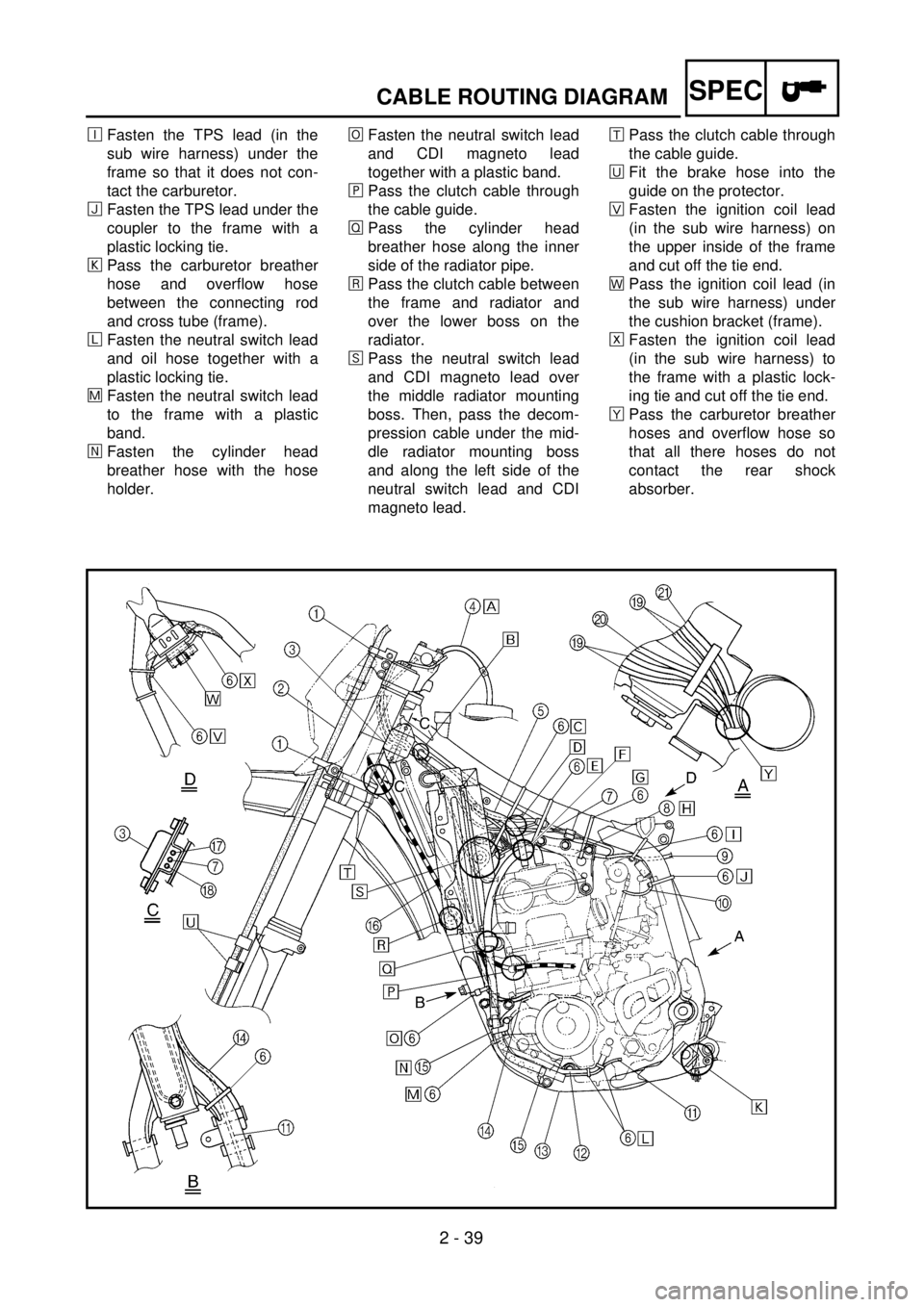
é
Fasten the TPS lead (in the
sub wire harness) under the
frame so that it does not con-
tact the carburetor.
ï
Fasten the TPS lead under the
coupler to the frame with a
plastic locking tie.
ð
Pass the carburetor breather
hose and overflow hose
between the connecting rod
and cross tube (frame).
ñ
Fasten the neutral switch lead
and oil hose together with a
plastic locking tie.
÷
Fasten the neutral switch lead
to the frame with a plastic
band.
öFasten the cylinder head
breather hose with the hose
holder.¯Fasten the neutral switch lead
and CDI magneto lead
together with a plastic band.
¸Pass the clutch cable through
the cable guide.
ÎPass the cylinder head
breather hose along the inner
side of the radiator pipe.
åPass the clutch cable between
the frame and radiator and
over the lower boss on the
radiator.
êPass the neutral switch lead
and CDI magneto lead over
the middle radiator mounting
boss. Then, pass the decom-
pression cable under the mid-
dle radiator mounting boss
and along the left side of the
neutral switch lead and CDI
magneto lead.æPass the clutch cable through
the cable guide.
èFit the brake hose into the
guide on the protector.
×Fasten the ignition coil lead
(in the sub wire harness) on
the upper inside of the frame
and cut off the tie end.
ãPass the ignition coil lead (in
the sub wire harness) under
the cushion bracket (frame).
ÅFasten the ignition coil lead
(in the sub wire harness) to
the frame with a plastic lock-
ing tie and cut off the tie end.
çPass the carburetor breather
hoses and overflow hose so
that all there hoses do not
contact the rear shock
absorber.
Page 221 of 762

SPEC
2 - 39
CHEMINEMENT DES CABLES
KABELFÜHRUNG
DIAGRAMA DE RUTA DE CABLES
éDas TPS-Kabel (im Nebenkabel-
baum) unter dem Rahmen befestigen,
damit es nicht in Kontakt mit dem Ver-
gaser kommt.
ïDie TPS-Leitung unter dem Koppler
am Rahmen mit einem Kabelbinder
befestigen.
ðDen Vergaser-Entlüftungsschlauch
und den Auslaufschutzschlauch zwi-
schen Übertragungshebel und Rah-
men-Querrohr führen.
ñDas Leerlaufschalter-Kabel und den
Ölschlauch mit mehrf. verwendb. Ka-
belbinder befestigen.
÷Das Leerlaufschalter-Kabel mit mehrf.
verwendb. Kabelbinder am Rahmen
befestigen.
öDen Zylinderkopf-Entlüftungsschlauch
mit der Schlauchhalterung befestigen.
¯Den Zylinderkopf-Entlüftungsschlauch
und das CDI-Schwungradmagnetzün-
der-Kabel mit mehrf. verwendb. Ka-
belbinder befestigen.
¸Den Kupplungsseilzug durch die Ka-
belführung führen.
ÎDen Zylinderkopf-Entlüftungsschlauch
hinter der Kühlerleitung führen.
åDen Kupplungsseilzug zwischen Rah-
men und Kühler und über der unteren
Büchse des Kühlers verlegen.
êDas Leerlaufschalter-Kabel und das
CDI-Schwungradmagnetzünder-Ka-
bel über der mittleren Kühlerhalterung
führen. Dann den Dekompressions-
zug unter der mittleren Kühlerhalte-
rung und links vom Leerlaufschalter-
Kabel und CDI-Schwungradmagnet-
zünder-Kabel führen.
æDen Kupplungsseilzug durch die Ka-
belführung verlegen.
èDen Bremsschlauch in die Führung
am Protektor einsetzen.
×Die Zündspulenleitung (im Nebenka-
belbaum) an der Oberseite des Rah-
mens befestigen, und das Bandende
abschneiden.
ãDie Zündspulenleitung (im Nebenka-
belbaum) unter dem Polsterbügel
(Rahmen) verlegen.
ôDie Zündspulenleitung (im Nebenka-
belbaum) mit einem Kabelbinder am
Rahmen befestigen, und das Banden-
de abschneiden.
çDie Vergaser-Entlüftungsschläuche
so führen, daß keiner der Schläuche
das Federbein berührt. éAttacher le fil de TPS (dans le faisceau de
fils secondaires) sous le cadre, en veillant
à ce qu’il ne touche pas le carburateur.
ïAttacher le fil de TPS sous le raccord au
cadre à l’aide d’une attache en plastique.
ðFaire passer le reniflard de carburateur et
le flexible de trop-plein entre la bielle et
le tube transversal du cadre.
ñAttacher le fil de contacteur de point mort
et le flexible d’huile à l’aide d’une attache
en plastique.
÷Attacher le fil de contacteur de point mort
au cadre à l’aide d’une attache en plasti-
que.
öAttacher le reniflard de culasse à l’aide du
support de flexible.
¯Faire passer le reniflard de culasse entre
le support inférieur de moteur et le fil de
magnéto CDI.
¸Faire passer le câble d’embrayage par le
guide du câble.
ÎFaire passer le reniflard de culasse der-
rière le tuyau du radiateur.
åFaire passer le câble d’embrayage entre le
cadre et le radiateur et au-dessus de la
noix inférieure du radiateur.
êFaire passer le fil de contacteur de point
mort et le fil de magnéto CDI par-dessus
la noix de montage centrale du radiateur.
Faire passer ensuite le câble du décom-
presseur sous la noix de montage centrale
du radiateur, puis le long du côté gauche
du fil de contacteur de point mort et du fil
de magnéto CDI.
æFaire passer le câble d’embrayage par le
guide de câble.
èFaire passer le tuyau de frein par le guide
de la protection.
×Attacher le fil de bobine d’allumage (dans
le faisceau de fils secondaires) sur la par-
tie intérieure et supérieure du cadre et
couper l’extrémité de l’attache.
ãFaire passer le fil de bobine d’allumage
(dans le faisceau de fils secondaires) sous
le support d’amortisseur (cadre).
ôAttacher le fil de bobine d’allumage (dans
le faisceau de fils secondaires) au cadre à
l’aide d’une attache en plastique et couper
l’extrémité de l’attache.
çAcheminer les reniflards de carburateur et
le flexible de trop-plein en veillant à ce
qu’ils ne touchent pas l’amortisseur
arrière.éSujetar el cable TPS (del sub-cableado)
por debajo del bastidor de modo que no se
ponga en contacto con el carburador.
ïSujetar el cable TPS por debajo del aco-
plador al bastidor mediante una conexión
plástica de cierre.
ðPasar el tubo respiradero del carburador y
el tubo de desbordamiento entre la biela y
el tubo cruzado (bastidor).
ñSujetar el cable del interruptor de punto
muerto y el tubo del aceite conjuntamente
con una conexión plástica de cierre.
÷Sujetar el cable del interruptor de punto
muerto al bastidor mediante una banda
plástica.
öSujetar el tubo respiradero de la culata
con el soporte del tubo.
¯Pasar el tubo respiradero de la culata entre
la ménsula del motor inferior y el cable
del magneto CDI.
¸Pasar el cable del embrague a través de la
guía del cable.
ÎPasar el tubo respiradero de la culata por
el lado interno del tubo del radiador.
åPasar el cable del embrague entre el basti-
dor y el radiador y por encima de la parte
inferior del buje del radiador.
êPasar el cable del interruptor de punto
muerto y el cable del magneto CDI por
encima del buje de montaje del radiador
medio. A continuación, pasar el cable de
descompresión por debajo del buje de
montaje del radiador medio y por el lado
izquierdo del cable del interruptor de
punto muerto y el cable del magneto CDI.
æPasar el cable del embrague a través de la
guía del cable.
èColocar el tubo del freno dentro de la guía
del protector.
×Sujetar el cable de la bobina de encendido
(del sub-cableado) a la parte superior
interna del bastidor y cortar el extremo de
la conexión.
ãPasar el cable de la bobina de encendido
(del sub-cableado) por debajo de la mén-
sula amortiguadora (bastidor).
ôSujetar el cable de la bobina de encendido
(del sub-cableado) al bastidor mediante
una conexión plástica de cierre y cortar el
extremo de la conexión.
çPasar los tubos respiraderos del carbura-
dor y el tubo de desbordamiento de forma
que ninguno de los tubos entre en con-
tacto con el amortiguador trasero.
Page 222 of 762
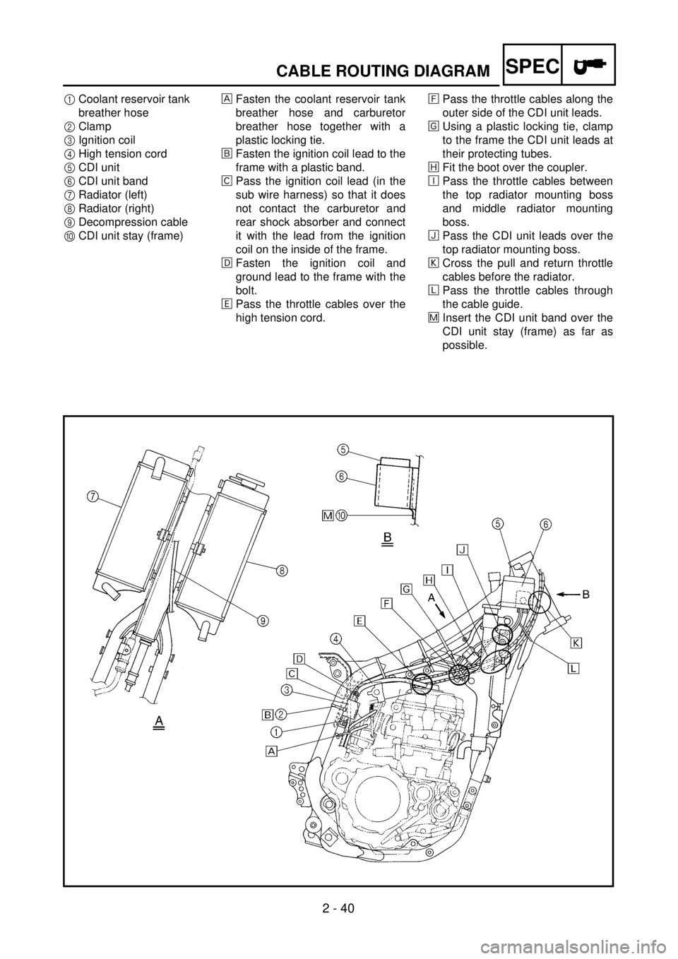
2 - 40
SPECCABLE ROUTING DIAGRAM
1Coolant reservoir tank
breather hose
2Clamp
3Ignition coil
4High tension cord
5CDI unit
6CDI unit band
7Radiator (left)
8Radiator (right)
9Decompression cable
0CDI unit stay (frame)Fasten the coolant reservoir tank
breather hose and carburetor
breather hose together with a
plastic locking tie.
õFasten the ignition coil lead to the
frame with a plastic band.
‚Pass the ignition coil lead (in the
sub wire harness) so that it does
not contact the carburetor and
rear shock absorber and connect
it with the lead from the ignition
coil on the inside of the frame.
ëFasten the ignition coil and
ground lead to the frame with the
bolt.
äPass the throttle cables over the
high tension cord.ìPass the throttle cables along the
outer side of the CDI unit leads.
íUsing a plastic locking tie, clamp
to the frame the CDI unit leads at
their protecting tubes.
îFit the boot over the coupler.
éPass the throttle cables between
the top radiator mounting boss
and middle radiator mounting
boss.
ïPass the CDI unit leads over the
top radiator mounting boss.
ðCross the pull and return throttle
cables before the radiator.
ñPass the throttle cables through
the cable guide.
÷Insert the CDI unit band over the
CDI unit stay (frame) as far as
possible.
Page 223 of 762

SPEC
2 - 40
CHEMINEMENT DES CABLES
KABELFÜHRUNG
DIAGRAMA DE RUTA DE CABLES
1Kühlmittelausgleichstank-Lüftungs-
schlauch
2Kabelbinder
3Zündspule
4Hochspannungskabel
5CDI-Zündbox
6CDI-Zündbox-Befestigungsband
7Kühler (links)
8Kühler (rechts)
9Dekompressionszug
0CDI-Zündbox-Halterung
Den Kühlmittelausgleichstank-Lüf-
tungsschlauch und Vergaser-Lüf-
tungsschlauch zusammen mit einem
Kabelbinder verbinden.
õDas Zündspulen-Kabel mit mehrf. ver-
wendb. Kabelbinder am Rahmen be-
festigen.
‚Die Zündspulenleitung (im Nebenka-
belbaum) so durchführen, daß sie
nicht den Vergaser und hinteren
Stoßdämpfer berührt und mit der
Leitung von der Zündspule innen am
Rahmen verbinden.
ëDie Zündspulen- und Massekabel mit
am Rahmen festschrauben.
äDie Gasseilzüge über das Hochspan-
nungskabel führen.
ìDie Gasseilzüge vor dem CDI-Zünd-
box-Leitungen führen.
íMit einem Einweg-Kabelbinder die
Schutzrohre der Anschlußkabel der
CDI-Einheit am Rahmen befestigen.
îDie Tülle über den Koppler setzen.
éDie Gasseilzüge zwischen der oberen
Kühlerhalterung und der mittleren
Kühlerhalterung führen.
ïDas CDI-Zündbox-Kabel über der
oberen Kühlerhalterung führen.
ðDie Gaszug- und -rückzugseile vor
dem Kühler überkreuzen.
ñDie Gasseilzüge durch die Kabelfüh-
rung am Rahmen verlegen.
÷Das CDI-Zündbox-Befestigungsband
so weit wie möglich über der CDI-
Zündbox-Halterung führen. 1Flexible de reniflard du réservoir de
liquide de refroidissement
2Bride
3Bobine d’allumage
4Cordon de haute tension
5Bloc CDI
6Attache de bloc CDI
7Radiateur (gauche)
8Radiateur (droit)
9Câble du décompresseur
0Support du bloc CDI (cadre)
Attacher le flexible de reniflard du réser-
voir de liquide de refroidissement et le
flexible de reniflard de carburateur
ensemble à l’aide d’une attache en plasti-
que.
õAttacher le fil de bobine d’allumage au
cadre à l’aide d’une attache en plastique.
‚Faire passer le fil de bobine d’allumage
(dans le faisceau de fils secondaires) de
sorte qu’il ne touche pas le carburateur et
l’amortisseur arrière et le raccorder avec
le fil de la bobine d’allumage sur l’inté-
rieur du cadre.
ëAttacher le fil de bobine d’allumage et le
fil de la masse au cadre à l’aide d’un bou-
lon.
äFaire passer les câbles d’accélération par-
dessus le cordon de haute tension.
ìFaire passer les câbles d’accélération par-
devant les fils du bloc CDI.
íBrider les fils du bloc CDI au cadre à
l’aide d’un lien en plastique. Les attacher
à leur tube de protection.
îEmboîter la tétine sur le coupleur.
éFaire passer les câbles d’accélération
entre la noix de montage supérieur et cen-
trale du radiateur.
ïFaire passer les fils du bloc CDI par-des-
sus la noix de montage supérieure du
radiateur.
ðCroiser les deux câbles d’accélérateur
devant le radiateur.
ñFaire passer les câbles d’accélérateur par
le guide de câble sur le cadre.
÷Insérer l’attache du bloc CDI par-dessus
le support du bloc CDI (cadre) aussi loin
que possible.1Tubo respiradero del depósito de reserva
del refrigerante
2Abrazadera
3Bobina de encendido
4Cable de alta tensión
5Unidad CDI
6Banda de la unidad CDI
7Radiador (izquierdo)
8Radiador (derecho)
9Cable de descompresión
0Soporte de la unidad CDI (bastidor)
Sujetar el tubo respiradero del depósito de
reserva del refrigerante y el tubo respira-
dero del carburador conjuntamente con
mediante una conexión plástica de cierre.
õSujetar el cable de la bobina de encendido
al bastidor con una banda plástica.
‚Pasar el cable de la bobina de encendido
(del sub-cableado) de forma que no esté
en contacto con el carburador y con el
amortiguador trasero y conectarlo con el
cable que procede de la bobina de encen-
dido de la parte interior del bastidor.
ëSujetar la bobina de encendido y cable de
tierra al bastidor con el perno.
äPasar los cables del acelerador sobre el
cable de alta tensión.
ìPasar los cables del acelerador por el lado
exterior de los cables de la unidad CDI.
íUtilizando una conexión plástica de cie-
rre, sujetar los cables de la unidad CDI al
bastidor en sus tubos protectores.
îColocar lafunda encima del alcoplador.
éPasar los cables del acelerador entre el
buje de montaje del radiador superior y el
buje de montaje del radiador medio.
ïPasar los cables de la unidad CDI por
encima del buje de montaje del radiador
superior.
ðCruzar los cables de avance y retroceso
del acelerador antes de llegar al radiador.
ñPasar los cables del acelerador a través de
la guía del cable del bastidor.
÷Insertar la banda de la unidad CDI por
encima del soporte de la unidad CDI (bas-
tidor )lo máximo posible.