warning light YAMAHA WR 426F 2001 Owners Manual
[x] Cancel search | Manufacturer: YAMAHA, Model Year: 2001, Model line: WR 426F, Model: YAMAHA WR 426F 2001Pages: 762, PDF Size: 62.36 MB
Page 284 of 762
3 - 25
INSP
ADJ
SPARK ARRESTER CLEANING (For USA)
WARNING
lBe sure the exhaust pipe and muffler are
cool before cleaning the spark arrester.
lDo not start the engine when cleaning the
exhaust system.
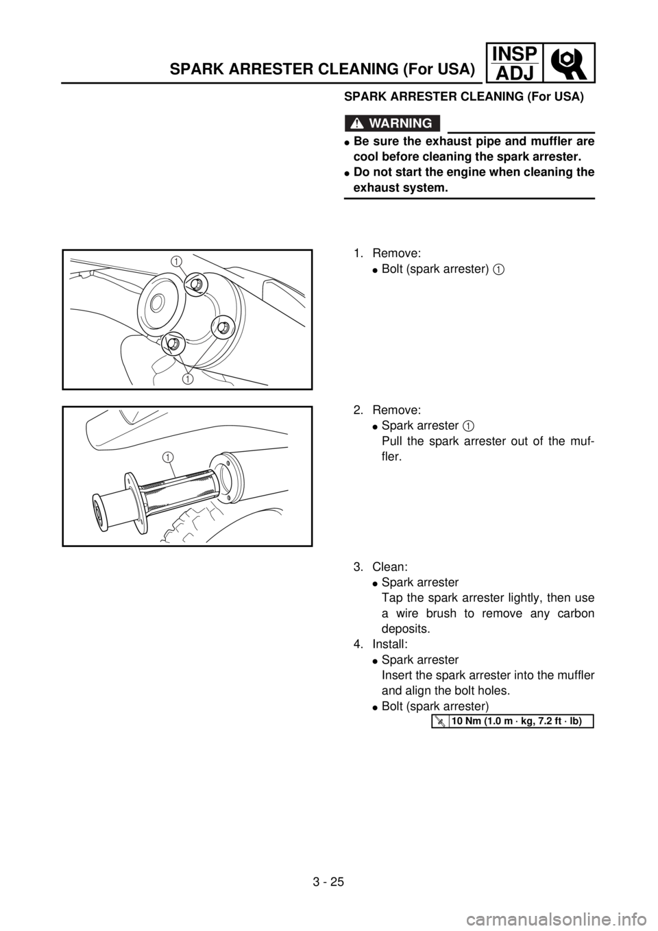
1. Remove:
lBolt (spark arrester) 1 1
1
2. Remove:
lSpark arrester 1
Pull the spark arrester out of the muf-
fler.
1
3. Clean:
lSpark arrester
Tap the spark arrester lightly, then use
a wire brush to remove any carbon
deposits.
4. Install:
lSpark arrester
Insert the spark arrester into the muffler
and align the bolt holes.
lBolt (spark arrester)
T R..10 Nm (1.0 m · kg, 7.2 ft · lb)
SPARK ARRESTER CLEANING (For USA)
Page 324 of 762
3 - 45
INSP
ADJ
STEERING HEAD INSPECTION AND ADJUSTMENT
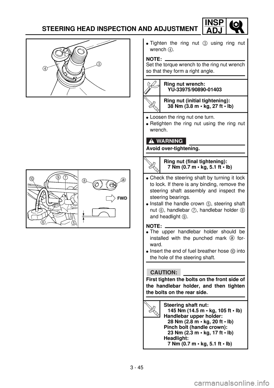
lTighten the ring nut 3 using ring nut
wrench 4.
NOTE:
Set the torque wrench to the ring nut wrench
so that they form a right angle.
Ring nut wrench:
YU-33975/90890-01403
T R..
Ring nut (initial tightening):
38 Nm (3.8 m • kg, 27 ft • lb)
lLoosen the ring nut one turn.
lRetighten the ring nut using the ring nut
wrench.
WARNING
Avoid over-tightening.
T R..
Ring nut (final tightening):
7 Nm (0.7 m • kg, 5.1 ft • lb)
lCheck the steering shaft by turning it lock
to lock. If there is any binding, remove the
steering shaft assembly and inspect the
steering bearings.
lInstall the handle crown 5, steering shaft
nut 6, handlebar 7, handlebar holder 8
and headlight 9.
NOTE:
lThe upper handlebar holder should be
installed with the punched mark a for-
ward.
lInsert the end of fuel breather hose 0 into
the hole of the steering shaft.
CAUTION:
First tighten the bolts on the front side of
the handlebar holder, and then tighten
the bolts on the rear side.
T R..
Steering shaft nut:
145 Nm (14.5 m • kg, 105 ft • lb)
Handlebar upper holder:
28 Nm (2.8 m • kg, 20 ft • lb)
Pinch bolt (handle crown):
23 Nm (2.3 m • kg, 17 ft • lb)
Headlight:
7 Nm (0.7 m • kg, 5.1 ft • lb)
Page 332 of 762
3 - 49
INSP
ADJ
REPLACING THE HEADLIGHT BULBS
REPLACING THE HEADLIGHT BULBS
1. Remove:
lHeadlight
Refer to “SEAT, FUEL TANK AND
SIDE COVERS” section in the CHAP-
TER 4.
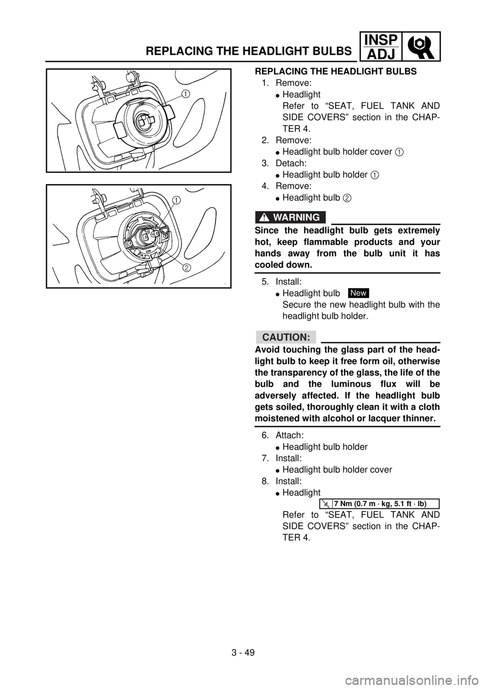
2. Remove:
lHeadlight bulb holder cover 1
3. Detach:
lHeadlight bulb holder 1
4. Remove:
lHeadlight bulb 2
WARNING
Since the headlight bulb gets extremely
hot, keep flammable products and your
hands away from the bulb unit it has
cooled down.
5. Install:
lHeadlight bulb
Secure the new headlight bulb with the
headlight bulb holder.
CAUTION:
Avoid touching the glass part of the head-
light bulb to keep it free form oil, otherwise
the transparency of the glass, the life of the
bulb and the luminous flux will be
adversely affected. If the headlight bulb
gets soiled, thoroughly clean it with a cloth
moistened with alcohol or lacquer thinner.
6. Attach:
lHeadlight bulb holder
7. Install:
lHeadlight bulb holder cover
8. Install:
lHeadlight
Refer to “SEAT, FUEL TANK AND
SIDE COVERS” section in the CHAP-
TER 4.
New
T R..7 Nm (0.7 m · kg, 5.1 ft · lb)
Page 582 of 762
5 - 19
CHASFRONT BRAKE AND REAR BRAKE
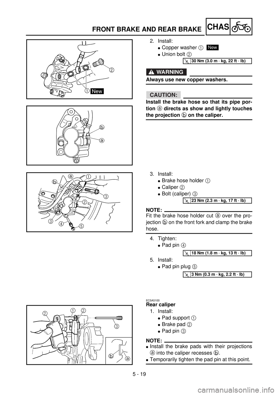
2. Install:
lCopper washer 1
lUnion bolt 2
WARNING
Always use new copper washers.
CAUTION:
Install the brake hose so that its pipe por-
tion a directs as show and lightly touches
the projection b on the caliper.
New
T R..30 Nm (3.0 m · kg, 22 ft · lb)
3. Install:
lBrake hose holder 1
lCaliper 2
lBolt (caliper) 3
NOTE:
Fit the brake hose holder cut a over the pro-
jection b on the front fork and clamp the brake
hose.
4. Tighten:
lPad pin 4
5. Install:
lPad pin plug 5
T R..23 Nm (2.3 m · kg, 17 ft · lb)
T R..18 Nm (1.8 m · kg, 13 ft · lb)
T R..3 Nm (0.3 m · kg, 2.2 ft · lb)
EC5A5100
Rear caliper
1. Install:
lPad support 1
lBrake pad 2
lPad pin 3
NOTE:
lInstall the brake pads with their projections
a into the caliper recesses b.
lTemporarily tighten the pad pin at this point.
Page 594 of 762
5 - 25
CHASFRONT BRAKE AND REAR BRAKE
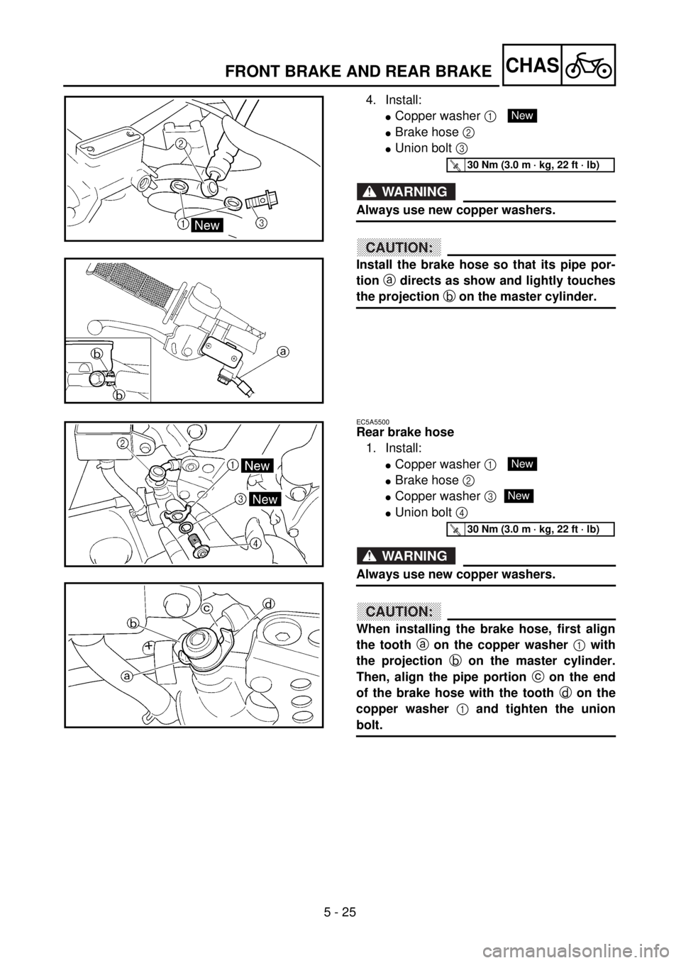
4. Install:
lCopper washer 1
lBrake hose 2
lUnion bolt 3
WARNING
Always use new copper washers.
CAUTION:
Install the brake hose so that its pipe por-
tion a directs as show and lightly touches
the projection b on the master cylinder.
New
T R..30 Nm (3.0 m · kg, 22 ft · lb)
EC5A5500
Rear brake hose
1. Install:
lCopper washer 1
lBrake hose 2
lCopper washer 3
lUnion bolt 4
WARNING
Always use new copper washers.
CAUTION:
When installing the brake hose, first align
the tooth a on the copper washer 1 with
the projection b on the master cylinder.
Then, align the pipe portion c on the end
of the brake hose with the tooth d on the
copper washer 1 and tighten the union
bolt.
New
New
T R..30 Nm (3.0 m · kg, 22 ft · lb)
Page 600 of 762
5 - 28
CHASFRONT FORK
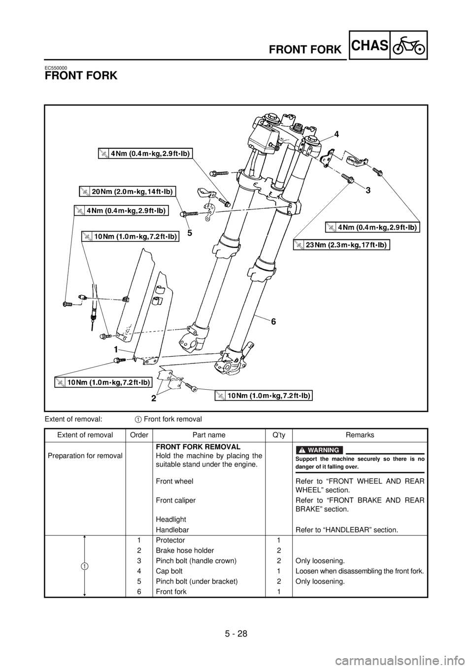
EC550000
FRONT FORK
Extent of removal:1 Front fork removal
Extent of removal Order Part name Q’ty Remarks
Preparation for removalFRONT FORK REMOVAL
Hold the machine by placing the
suitable stand under the engine.
WARNING
Support the machine securely so there is nodanger of it falling over.
Front wheel Refer to “FRONT WHEEL AND REAR
WHEEL” section.
Front caliper Refer to “FRONT BRAKE AND REAR
BRAKE” section.
Headlight
Handlebar Refer to “HANDLEBAR” section.
1 Protector 1
2 Brake hose holder 2
3 Pinch bolt (handle crown) 2 Only loosening.
4 Cap bolt 1Loosen when disassembling the front fork.
5 Pinch bolt (under bracket) 2 Only loosening.
6 Front fork 1
1
Page 632 of 762
5 - 44
CHASHANDLEBAR
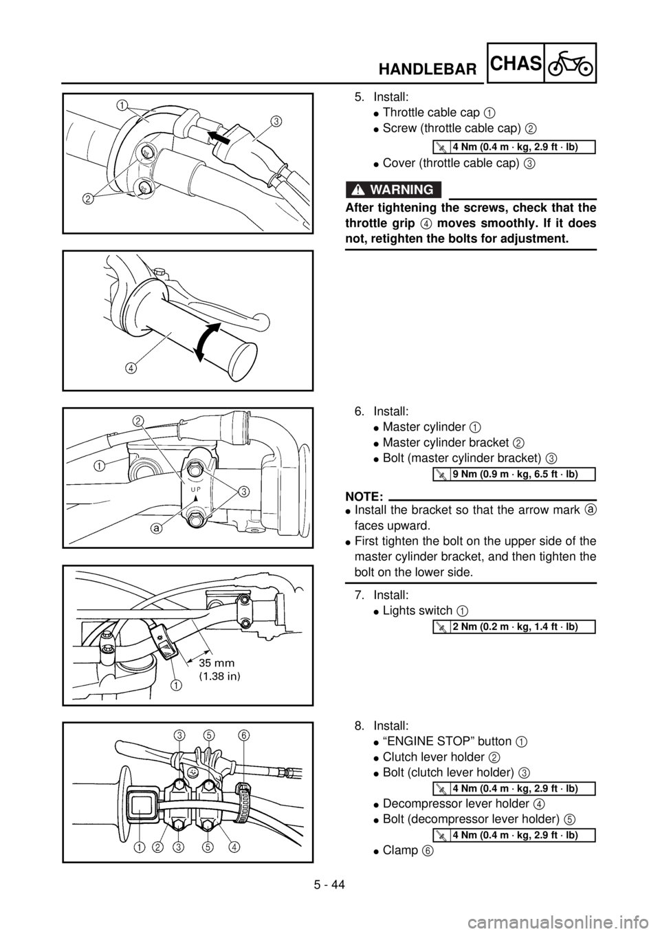
5. Install:
lThrottle cable cap 1
lScrew (throttle cable cap) 2
lCover (throttle cable cap) 3
WARNING
After tightening the screws, check that the
throttle grip 4 moves smoothly. If it does
not, retighten the bolts for adjustment.
T R..4 Nm (0.4 m · kg, 2.9 ft · lb)
6. Install:
lMaster cylinder 1
lMaster cylinder bracket 2
lBolt (master cylinder bracket) 3
NOTE:
lInstall the bracket so that the arrow mark a
faces upward.
lFirst tighten the bolt on the upper side of the
master cylinder bracket, and then tighten the
bolt on the lower side.
7. Install:
lLights switch 1
T R..9 Nm (0.9 m · kg, 6.5 ft · lb)
T R..2 Nm (0.2 m · kg, 1.4 ft · lb)
8. Install:
l“ENGINE STOP” button 1
lClutch lever holder 2
lBolt (clutch lever holder) 3
lDecompressor lever holder 4
lBolt (decompressor lever holder) 5
lClamp 6
T R..4 Nm (0.4 m · kg, 2.9 ft · lb)
T R..4 Nm (0.4 m · kg, 2.9 ft · lb)
Page 636 of 762
5 - 46
CHAS
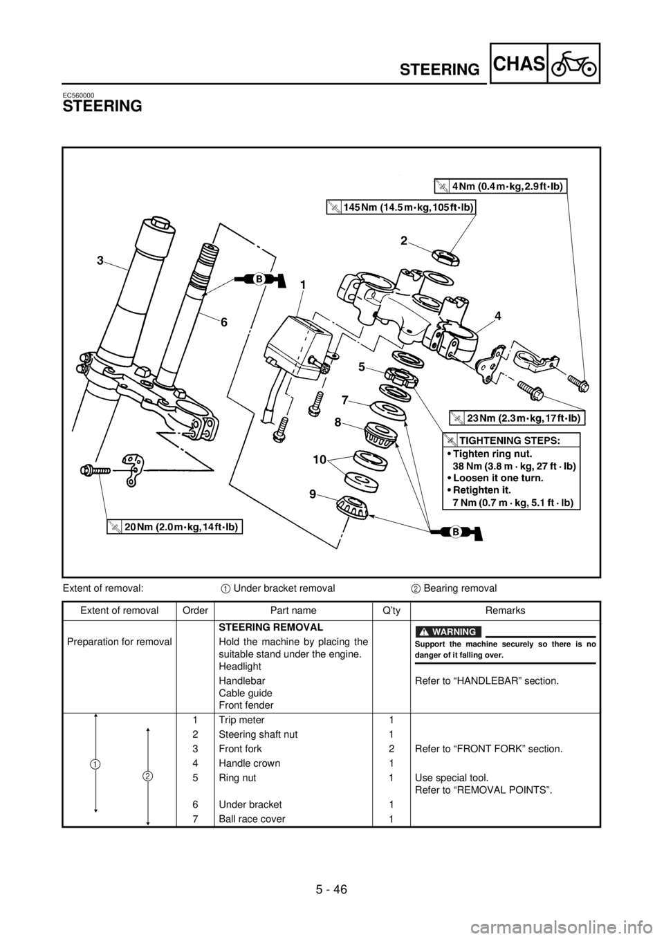
EC560000
STEERING
Extent of removal:1 Under bracket removal2 Bearing removal
Extent of removal Order Part name Q’ty Remarks
STEERING REMOVAL
WARNING
Support the machine securely so there is nodanger of it falling over.
Preparation for removal Hold the machine by placing the
suitable stand under the engine.
Headlight
Handlebar
Cable guide
Front fenderRefer to “HANDLEBAR” section.
1 Trip meter 1
2 Steering shaft nut 1
3 Front fork 2 Refer to “FRONT FORK” section.
4 Handle crown 1
5 Ring nut 1 Use special tool.
Refer to “REMOVAL POINTS”.
6 Under bracket 1
7Ball race cover
1
2
1
STEERING
Page 662 of 762

5 - 59
CHASREAR SHOCK ABSORBER
EC580000
REAR SHOCK ABSORBER
Extent of removal:1 Rear shock absorber removal2 Rear shock absorber disassembly
Extent of removal Order Part name Q’ty Remarks
Preparation for removalREAR SHOCK ABSORBER
REMOVAL
Hold the machine by placing the
suitable stand under the engine.
WARNING
Support the machine securely so there is nodanger of it falling over.
Seat, fitting band and side covers Refer to “SEAT, FUEL TANK AND SIDE
COVERS” section in the CHAPTER 4.
Silencer Refer to “EXHAUST PIPE AND
SILENCER” section in the CHAPTER 4.
Drain the coolant. Refer to “COOLANT REPLACEMENT”
section in the CHAPTER 3.
Coolant reservoir tank Refer to “RADIATOR” section in the
CHAPTER 4.
1 Tail light connector 2
2 Band 2
3 Bolt (reservoir tank) 1
4 Clamp (air cleaner joint) 1 Only loosening.
5 Rear frame 1
6 Bolt (rear shock absorber-relay arm) 1Hold the swingarm.
7 Bolt (rear shock absorber-frame) 1
8 Rear shock absorber 1
12