check oil YAMAHA WR 450F 2006 Manuale de Empleo (in Spanish)
[x] Cancel search | Manufacturer: YAMAHA, Model Year: 2006, Model line: WR 450F, Model: YAMAHA WR 450F 2006Pages: 786, tamaño PDF: 22.49 MB
Page 516 of 786

4 - 100
ENGCRANKCASE AND CRANKSHAFT
5. Install:
Dowel pin 1
O-ring 2
Crankcase (right)
To crankcase (left).
NOTE:
Fit the crankcase (right) onto the crankcase
(left). Tap lightly on the case with soft ham-
mer.
When installing the crankcase, the connect-
ing rod should be positioned at TDC (top
dead center).
New
6. Tighten:
Hose guide 1
Clutch cable holder 2
Bolt (clutch cable holder)
Bolt (crankcase)
NOTE:
Tighten the crankcase tightening bolts in
stage, using a crisscross pattern.
7. Install:
Oil delivery pipe
O-ring
Bolt (oil delivery pipe 2)
8. Install:
Timing chain
Timing chain guide (rear)
Bolt (timing chain guide)
9. Remove:
Sealant
Forced out on the cylinder mating surface.
10. Apply:
Engine oil
To the crank pin, bearing and oil delivery
hole.
11. Check:
Crankshaft and transmission operation.
Unsmooth operation → Repair.
T R..10 Nm (1.0 m · kg, 7.2 ft · lb)
T R..12 Nm (1.2 m · kg, 8.7 ft · lb)
New
T R..10 Nm (1.0 m · kg, 7.2 ft · lb)
T R..10 Nm (1.0 m · kg, 7.2 ft · lb)
Page 522 of 786
4 - 103
ENGTRANSMISSION, SHIFT CAM AND SHIFT FORK
EC4H4801
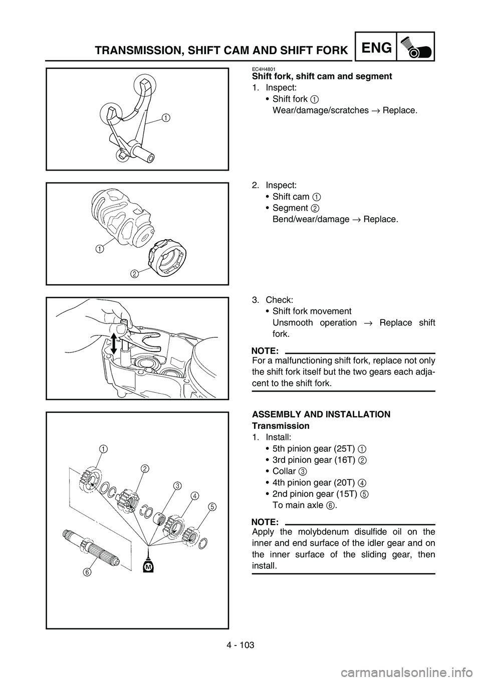
Shift fork, shift cam and segment
1. Inspect:
Shift fork 1
Wear/damage/scratches → Replace.
2. Inspect:
Shift cam 1
Segment 2
Bend/wear/damage → Replace.
3. Check:
Shift fork movement
Unsmooth operation → Replace shift
fork.
NOTE:
For a malfunctioning shift fork, replace not only
the shift fork itself but the two gears each adja-
cent to the shift fork.
ASSEMBLY AND INSTALLATION
Transmission
1. Install:
5th pinion gear (25T) 1
3rd pinion gear (16T) 2
Collar 3
4th pinion gear (20T) 4
2nd pinion gear (15T) 5
To main axle 6.
NOTE:
Apply the molybdenum disulfide oil on the
inner and end surface of the idler gear and on
the inner surface of the sliding gear, then
install.
Page 526 of 786
4 - 105
ENGTRANSMISSION, SHIFT CAM AND SHIFT FORK
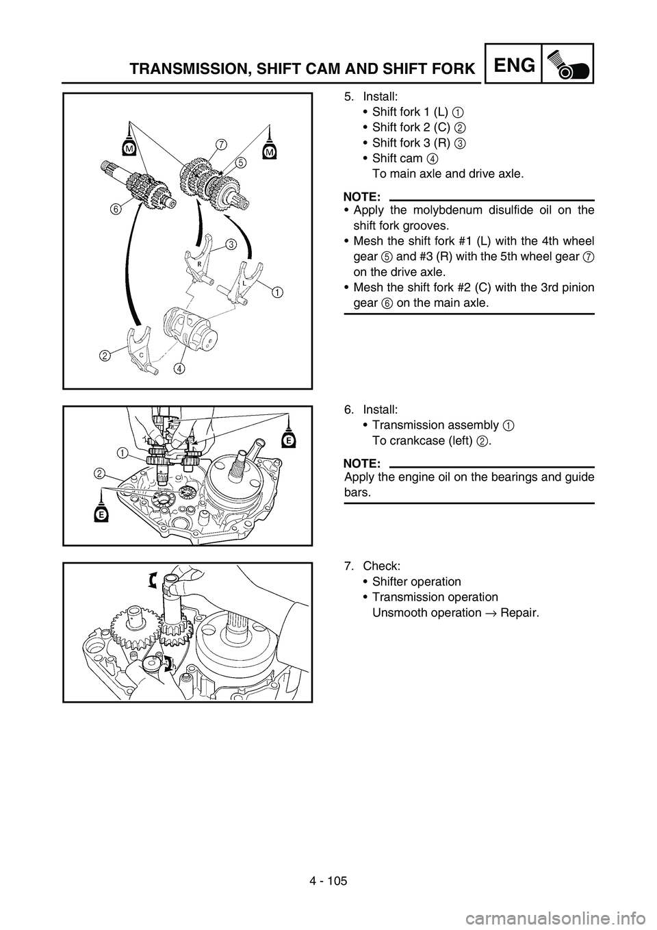
5. Install:
Shift fork 1 (L) 1
Shift fork 2 (C) 2
Shift fork 3 (R) 3
Shift cam 4
To main axle and drive axle.
NOTE:
Apply the molybdenum disulfide oil on the
shift fork grooves.
Mesh the shift fork #1 (L) with the 4th wheel
gear 5 and #3 (R) with the 5th wheel gear 7
on the drive axle.
Mesh the shift fork #2 (C) with the 3rd pinion
gear 6 on the main axle.
6. Install:
Transmission assembly 1
To crankcase (left) 2.
NOTE:
Apply the engine oil on the bearings and guide
bars.
7. Check:
Shifter operation
Transmission operation
Unsmooth operation → Repair.
Page 594 of 786
5 - 34
CHASFRONT FORK
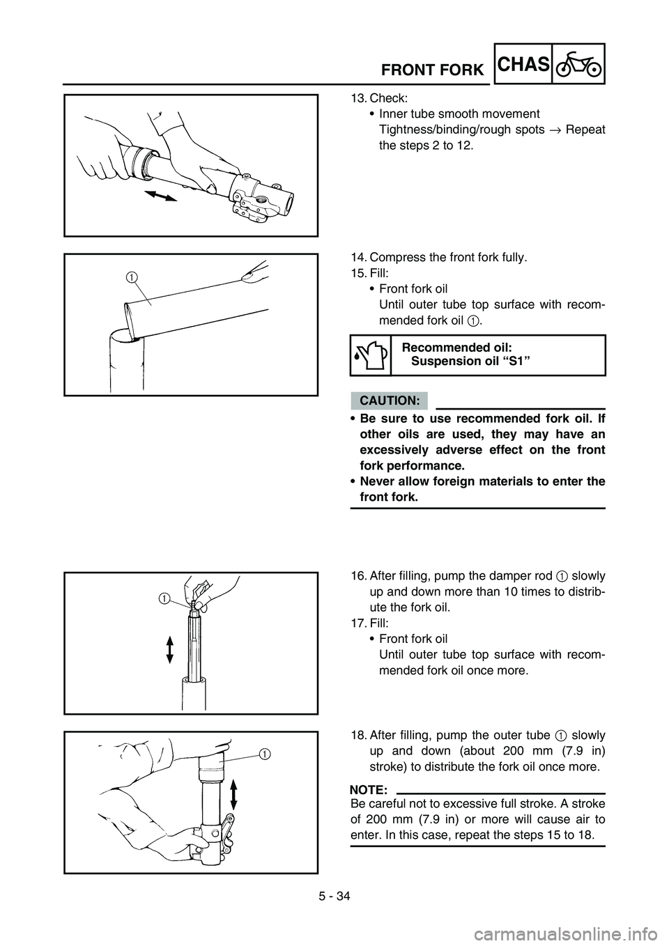
13. Check:
Inner tube smooth movement
Tightness/binding/rough spots → Repeat
the steps 2 to 12.
14. Compress the front fork fully.
15. Fill:
Front fork oil
Until outer tube top surface with recom-
mended fork oil 1.
CAUTION:
Be sure to use recommended fork oil. If
other oils are used, they may have an
excessively adverse effect on the front
fork performance.
Never allow foreign materials to enter the
front fork.
Recommended oil:
Suspension oil “S1”
16. After filling, pump the damper rod 1 slowly
up and down more than 10 times to distrib-
ute the fork oil.
17. Fill:
Front fork oil
Until outer tube top surface with recom-
mended fork oil once more.
18. After filling, pump the outer tube 1 slowly
up and down (about 200 mm (7.9 in)
stroke) to distribute the fork oil once more.
NOTE:
Be careful not to excessive full stroke. A stroke
of 200 mm (7.9 in) or more will cause air to
enter. In this case, repeat the steps 15 to 18.
Page 596 of 786
5 - 35
CHASFRONT FORK
19. Wait ten minutes until the air bubbles have
been removed from the front fork, and the
oil has dispense evenly in system before
setting recommended oil level.
NOTE:
Fill with the fork oil up to the top end of the
outer tube, or the fork oil will not spread over to
every part of the front forks, thus making it
impossible to obtain the correct level.
Be sure to fill with the fork oil up to the top of
the outer tube and bleed the front forks.
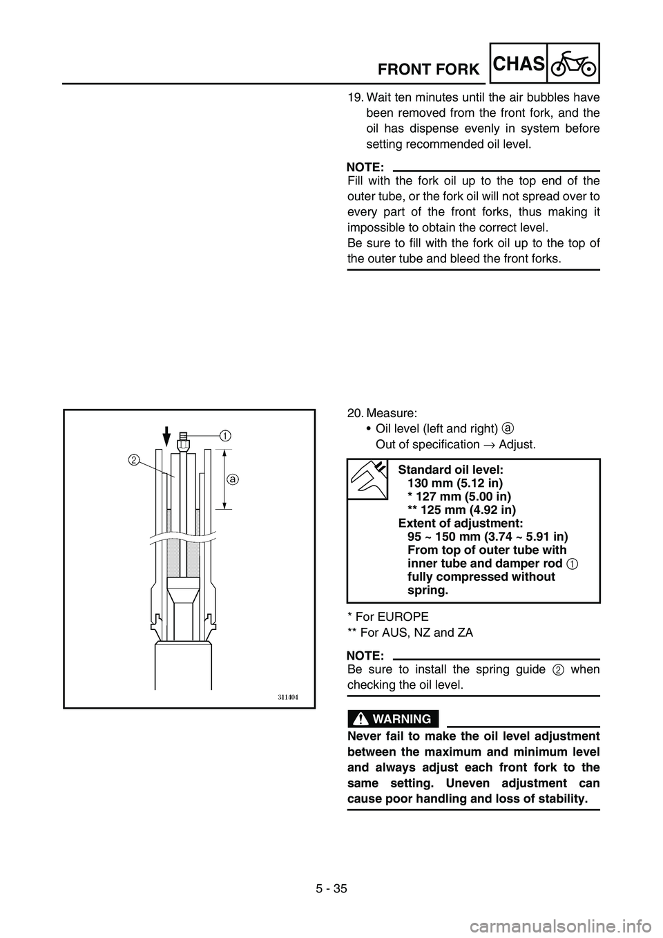
20. Measure:
Oil level (left and right) a
Out of specification → Adjust.
* For EUROPE
** For AUS, NZ and ZA
NOTE:
Be sure to install the spring guide 2 when
checking the oil level.
WARNING
Never fail to make the oil level adjustment
between the maximum and minimum level
and always adjust each front fork to the
same setting. Uneven adjustment can
cause poor handling and loss of stability.
Standard oil level:
130 mm (5.12 in)
* 127 mm (5.00 in)
** 125 mm (4.92 in)
Extent of adjustment:
95 ~ 150 mm (3.74 ~ 5.91 in)
From top of outer tube with
inner tube and damper rod
1
fully compressed without
spring.
Page 672 of 786
–+ELEC
6 - 3
IGNITION SYSTEM
EC620000
IGNITION SYSTEM
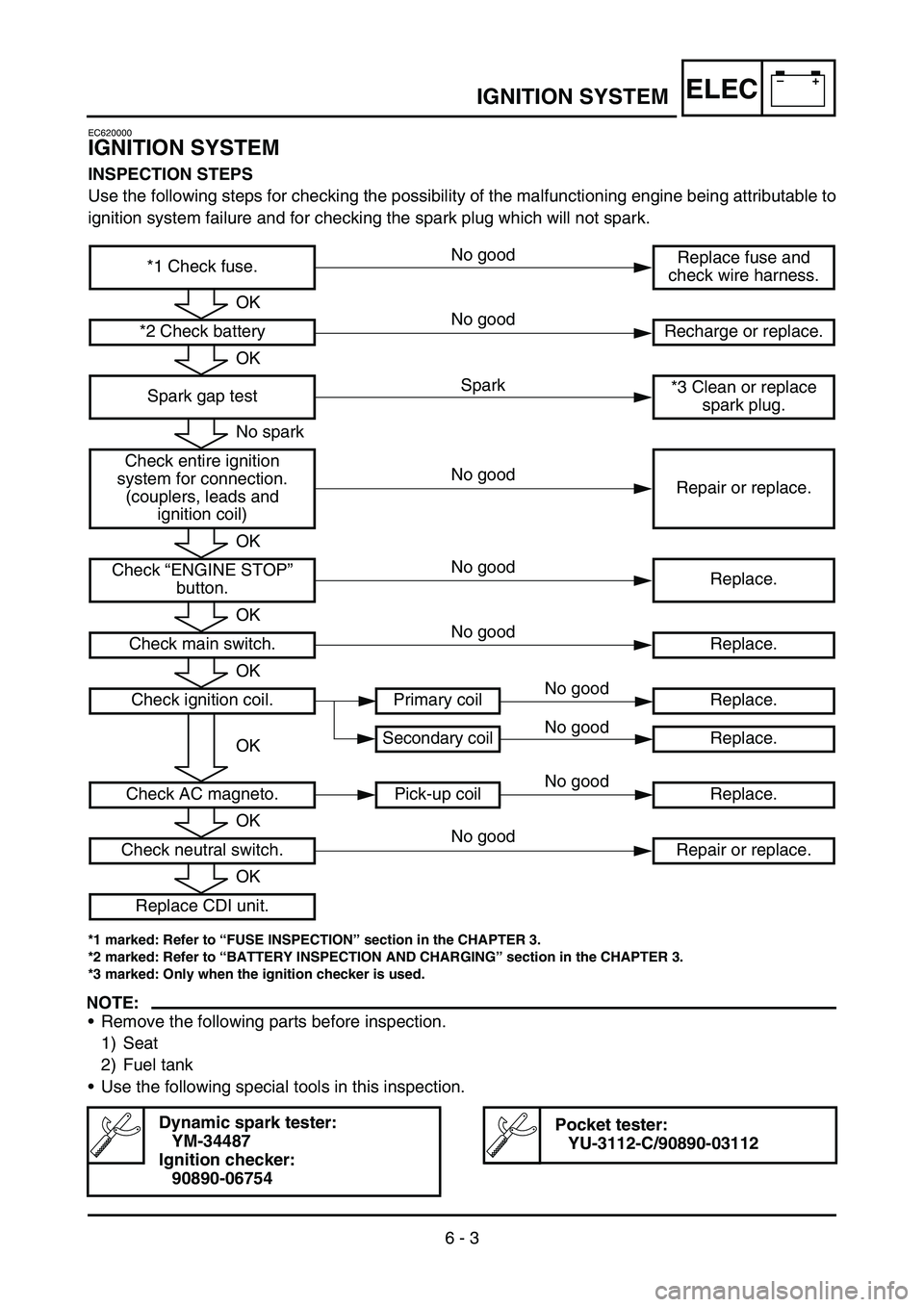
INSPECTION STEPS
Use the following steps for checking the possibility of the malfunctioning engine being attributable to
ignition system failure and for checking the spark plug which will not spark.
*1 marked: Refer to “FUSE INSPECTION” section in the CHAPTER 3.
*2 marked: Refer to “BATTERY INSPECTION AND CHARGING” section in the CHAPTER 3.
*3 marked: Only when the ignition checker is used.
NOTE:
•Remove the following parts before inspection.
1) Seat
2) Fuel tank
•Use the following special tools in this inspection.
Dynamic spark tester:
YM-34487
Ignition checker:
90890-06754Pocket tester:
YU-3112-C/90890-03112
*1 Check fuse.Replace fuse and
check wire harness.
*2 Check battery Recharge or replace.
Spark gap test*3 Clean or replace
spark plug.
Check entire ignition
system for connection.
(couplers, leads and
ignition coil)Repair or replace.
Check “ENGINE STOP”
button.Replace.
Check main switch. Replace.
Check ignition coil. Primary coil Replace.
Secondary coil Replace.
Check AC magneto. Pick-up coil Replace.
Check neutral switch. Repair or replace.
Replace CDI unit.
OK
OK
No spark
OK
OK
OK
OK
OK
OK
Spark No good
No good
No good
No good
No good No good
No good
No good
No good
Page 676 of 786
6 - 4
–+ELECIGNITION SYSTEM
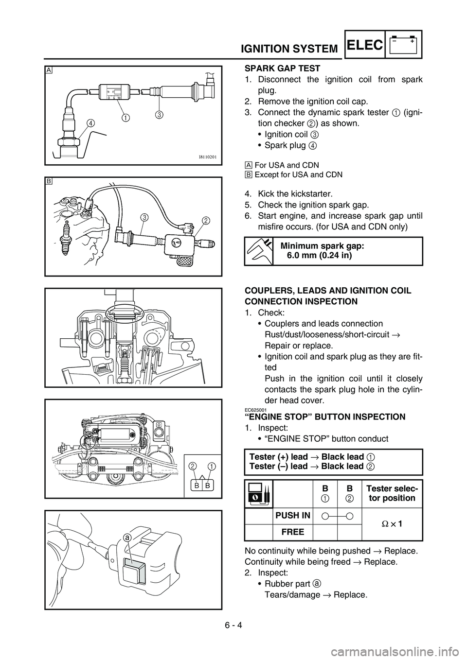
SPARK GAP TEST
1. Disconnect the ignition coil from spark
plug.
2. Remove the ignition coil cap.
3. Connect the dynamic spark tester 1 (igni-
tion checker 2) as shown.
•Ignition coil 3
•Spark plug 4
ÈFor USA and CDN
ÉExcept for USA and CDN
4. Kick the kickstarter.
5. Check the ignition spark gap.
6. Start engine, and increase spark gap until
misfire occurs. (for USA and CDN only)
Minimum spark gap:
6.0 mm (0.24 in)
È
É
COUPLERS, LEADS AND IGNITION COIL
CONNECTION INSPECTION
1. Check:
•Couplers and leads connection
Rust/dust/looseness/short-circuit →
Repair or replace.
•Ignition coil and spark plug as they are fit-
ted
Push in the ignition coil until it closely
contacts the spark plug hole in the cylin-
der head cover.
EC625001
“ENGINE STOP” BUTTON INSPECTION
1. Inspect:
•“ENGINE STOP” button conduct
No continuity while being pushed → Replace.
Continuity while being freed → Replace.
2. Inspect:
•Rubber part
a
Tears/damage → Replace. Tester (+) lead
→ Black lead
1
Tester (–) lead
→ Black lead
2
B
1 B
2 Tester selec-
tor position
PUSH IN
Ω
×
×× × 1
FREE
a
Page 680 of 786
6 - 6
–+ELECIGNITION SYSTEM
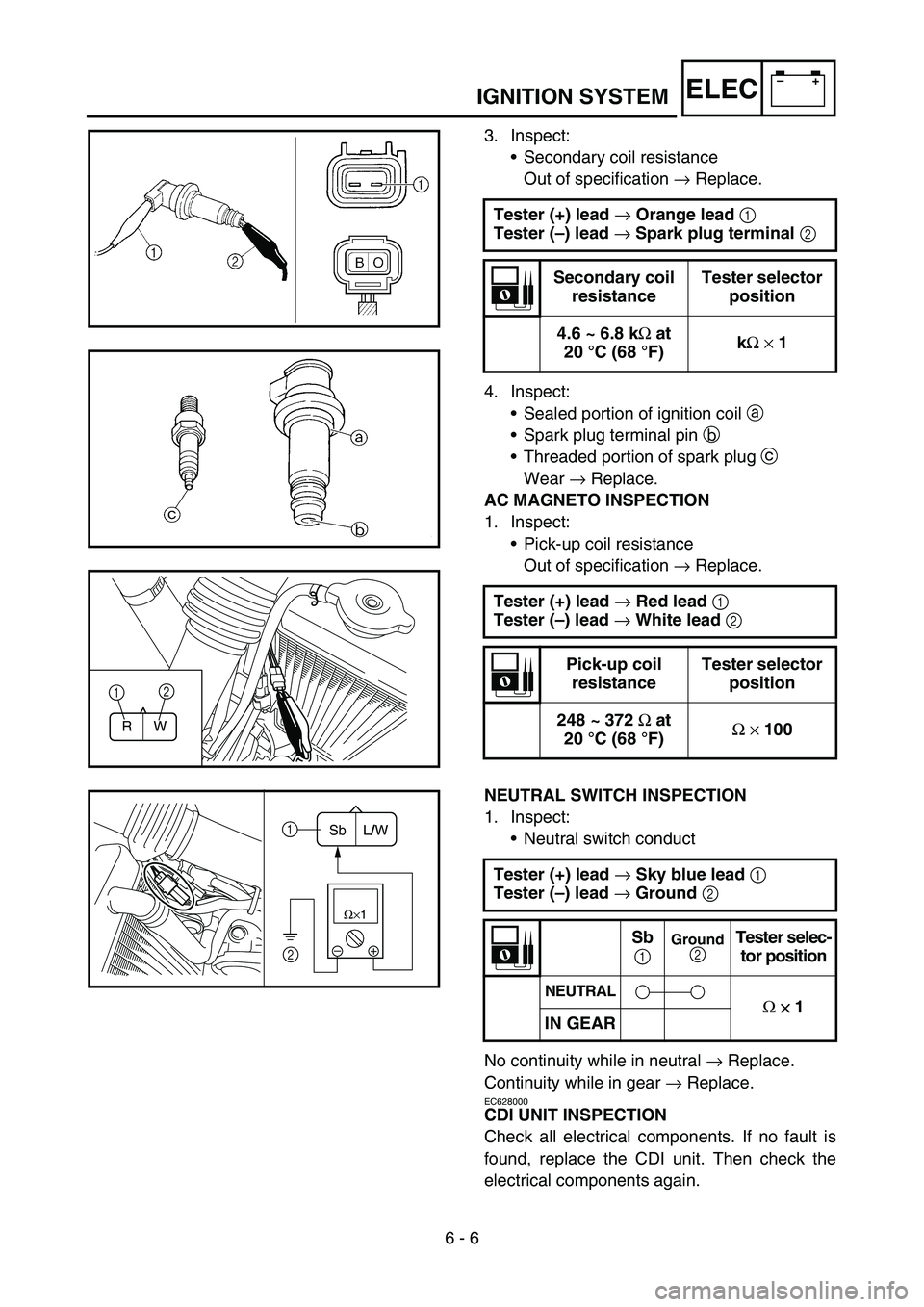
3. Inspect:
•Secondary coil resistance
Out of specification → Replace.
4. Inspect:
•Sealed portion of ignition coil a
•Spark plug terminal pin b
•Threaded portion of spark plug c
Wear → Replace.
AC MAGNETO INSPECTION
1. Inspect:
•Pick-up coil resistance
Out of specification → Replace.
NEUTRAL SWITCH INSPECTION
1. Inspect:
•Neutral switch conduct
No continuity while in neutral → Replace.
Continuity while in gear → Replace.
EC628000
CDI UNIT INSPECTION
Check all electrical components. If no fault is
found, replace the CDI unit. Then check the
electrical components again.Tester (+) lead
→ Orange lead
1
Tester (–) lead
→ Spark plug terminal
2
Secondary coil
resistanceTester selector
position
4.6 ~ 6.8 k
Ω at
20 °C (68 °F)k
Ω
× 1
Tester (+) lead
→ Red lead
1
Tester (–) lead
→ White lead
2
Pick-up coil
resistanceTester selector
position
248 ~ 372
Ω at
20 °C (68 °F)Ω
× 100
Tester (+) lead
→ Sky blue lead
1
Tester (–) lead
→ Ground
2
Sb
1 Ground 2
Tester selec-
tor position
NEUTRAL
Ω
×
×× × 1
IN GEAR
RW
12
–+ Ω×1
1
2L/W Sb
Page 704 of 786
–+ELEC
6 - 17
CHARGING SYSTEM
EC680000
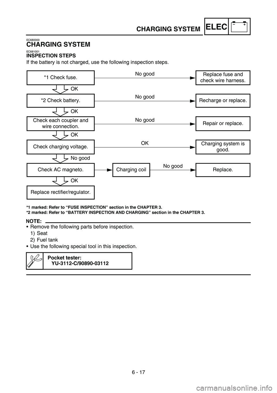
CHARGING SYSTEM
EC681001
INSPECTION STEPS
If the battery is not charged, use the following inspection steps.
*1 marked: Refer to “FUSE INSPECTION” section in the CHAPTER 3.
*2 marked: Refer to “BATTERY INSPECTION AND CHARGING” section in the CHAPTER 3.
NOTE:
•Remove the following parts before inspection.
1) Seat
2) Fuel tank
•Use the following special tool in this inspection.
Pocket tester:
YU-3112-C/90890-03112
*1 Check fuse.Replace fuse and
check wire harness.
*2 Check battery. Recharge or replace.
Check each coupler and
wire connection.Repair or replace.
Check charging voltage.Charging system is
good.
Check AC magneto. Charging coil Replace.
Replace rectifier/regulator.
OK
OK
OK
No good
OK
No good
No good No good
No good OK
Page 708 of 786
6 - 18
–+ELECCHARGING SYSTEM
EC624000
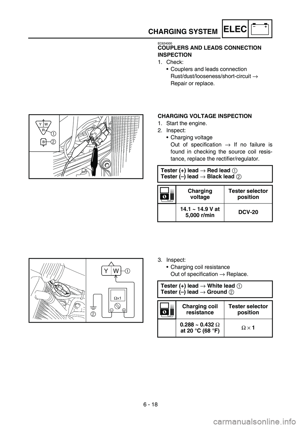
COUPLERS AND LEADS CONNECTION
INSPECTION
1. Check:
•Couplers and leads connection
Rust/dust/looseness/short-circuit →
Repair or replace.
CHARGING VOLTAGE INSPECTION
1. Start the engine.
2. Inspect:
•Charging voltage
Out of specification → If no failure is
found in checking the source coil resis-
tance, replace the rectifier/regulator.
Tester (+) lead
→ Red lead
1
Tester (–) lead
→ Black lead
2
Charging
voltageTester selector
position
14.1 ~ 14.9 V at
5,000 r/minDCV-20
R
BW Y1
2
3. Inspect:
•Charging coil resistance
Out of specification → Replace.
Tester (+) lead
→ White lead
1
Tester (–) lead
→ Ground
2
Charging coil
resistanceTester selector
position
0.288 ~ 0.432
Ω
at 20 °C (68 °F)Ω
× 1