brake light YAMAHA WR 450F 2006 Manuale de Empleo (in Spanish)
[x] Cancel search | Manufacturer: YAMAHA, Model Year: 2006, Model line: WR 450F, Model: YAMAHA WR 450F 2006Pages: 786, tamaño PDF: 22.49 MB
Page 26 of 786
GEN
INFO
1 - 1
DESCRIPTION
EC100000
GENERAL INFORMATION
EC110000
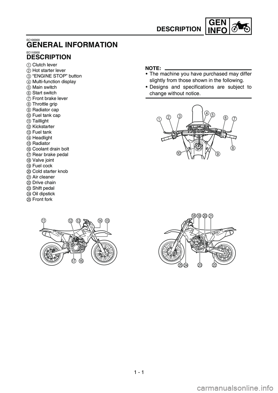
DESCRIPTION
1Clutch lever
2Hot starter lever
3“ENGINE STOP” button
4Multi-function display
5Main switch
6Start switch
7Front brake lever
8Throttle grip
9Radiator cap
0Fuel tank cap
ATaillight
BKickstarter
CFuel tank
DHeadlight
ERadiator
FCoolant drain bolt
GRear brake pedal
HValve joint
IFuel cock
JCold starter knob
KAir cleaner
LDrive chain
MShift pedal
NOil dipstick
OFront forkNOTE:
The machine you have purchased may differ
slightly from those shown in the following.
Designs and specifications are subject to
change without notice.
A
BCD
E
F G
1234
5
6
7
8
9 0
HI
J
K
L M
N O
Page 52 of 786
1 - 11
GEN
INFO
CONTROL FUNCTIONS
EC152000
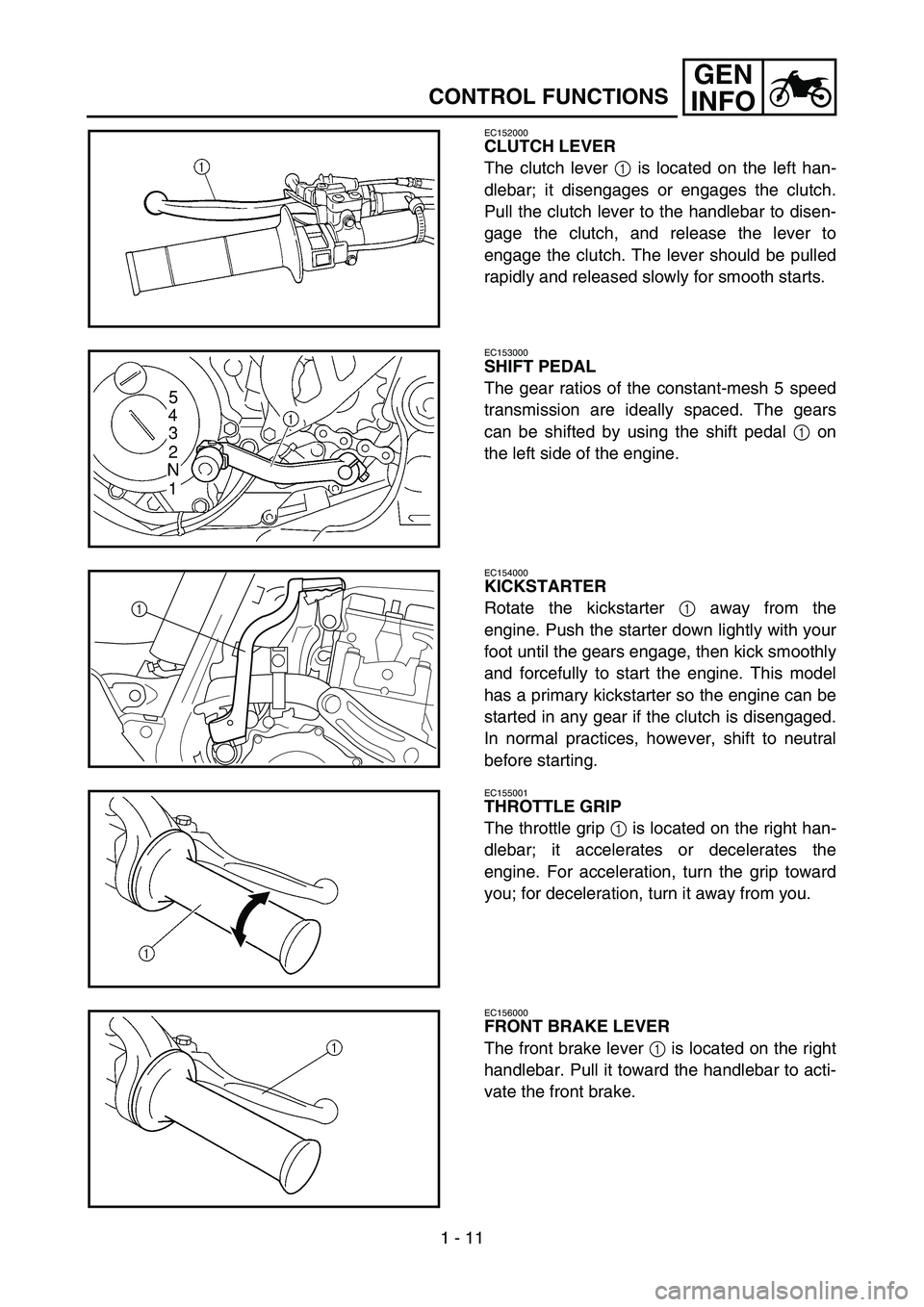
CLUTCH LEVER
The clutch lever 1 is located on the left han-
dlebar; it disengages or engages the clutch.
Pull the clutch lever to the handlebar to disen-
gage the clutch, and release the lever to
engage the clutch. The lever should be pulled
rapidly and released slowly for smooth starts.
EC153000
SHIFT PEDAL
The gear ratios of the constant-mesh 5 speed
transmission are ideally spaced. The gears
can be shifted by using the shift pedal 1 on
the left side of the engine.
EC154000
KICKSTARTER
Rotate the kickstarter 1 away from the
engine. Push the starter down lightly with your
foot until the gears engage, then kick smoothly
and forcefully to start the engine. This model
has a primary kickstarter so the engine can be
started in any gear if the clutch is disengaged.
In normal practices, however, shift to neutral
before starting.
1
EC155001
THROTTLE GRIP
The throttle grip 1 is located on the right han-
dlebar; it accelerates or decelerates the
engine. For acceleration, turn the grip toward
you; for deceleration, turn it away from you.
EC156000
FRONT BRAKE LEVER
The front brake lever 1 is located on the right
handlebar. Pull it toward the handlebar to acti-
vate the front brake.
Page 92 of 786
SPEC
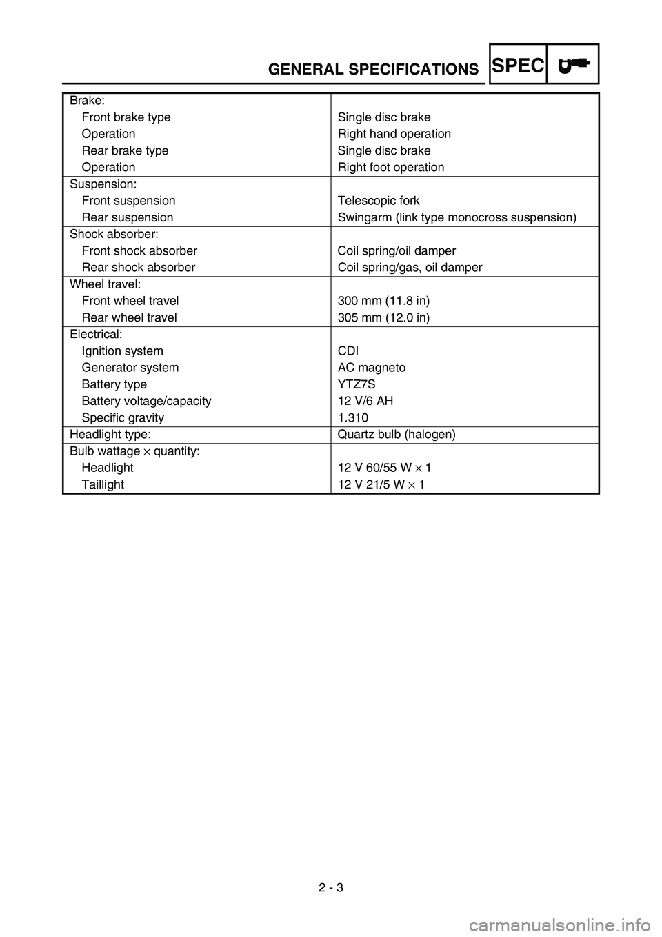
2 - 3 Brake:
Front brake type Single disc brake
Operation Right hand operation
Rear brake type Single disc brake
Operation Right foot operation
Suspension:
Front suspension Telescopic fork
Rear suspension Swingarm (link type monocross suspension)
Shock absorber:
Front shock absorber Coil spring/oil damper
Rear shock absorber Coil spring/gas, oil damper
Wheel travel:
Front wheel travel 300 mm (11.8 in)
Rear wheel travel 305 mm (12.0 in)
Electrical:
Ignition system CDI
Generator system AC magneto
Battery type YTZ7S
Battery voltage/capacity 12 V/6 AH
Specific gravity 1.310
Headlight type: Quartz bulb (halogen)
Bulb wattage × quantity:
Headlight 12 V 60/55 W × 1
Taillight 12 V 21/5 W × 1
GENERAL SPECIFICATIONS
Page 180 of 786
2 - 26
SPECCABLE ROUTING DIAGRAM
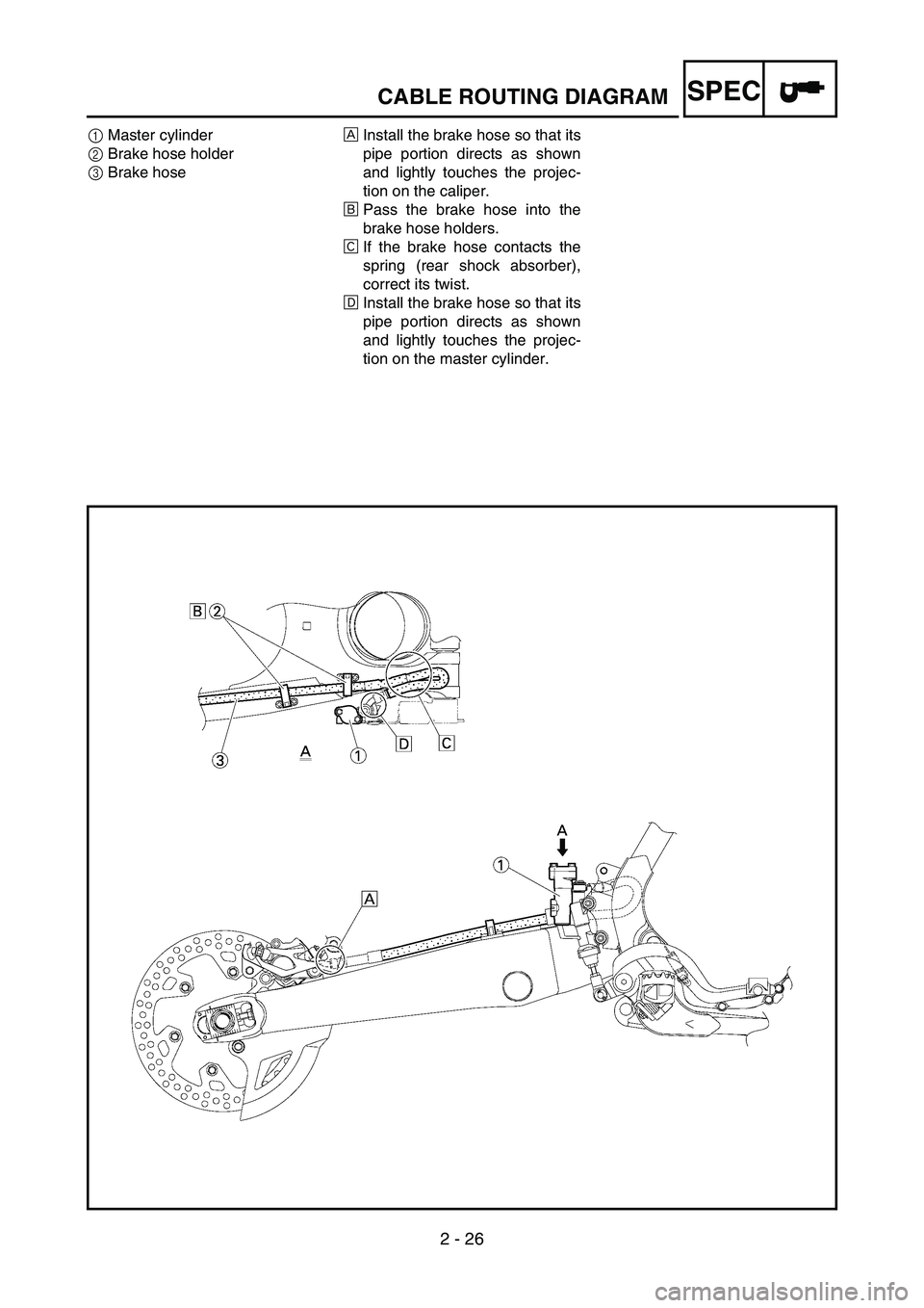
1Master cylinder
2Brake hose holder
3Brake hoseÈInstall the brake hose so that its
pipe portion directs as shown
and lightly touches the projec-
tion on the caliper.
ÉPass the brake hose into the
brake hose holders.
ÊIf the brake hose contacts the
spring (rear shock absorber),
correct its twist.
ËInstall the brake hose so that its
pipe portion directs as shown
and lightly touches the projec-
tion on the master cylinder.
Page 290 of 786
3 - 47
INSP
ADJ
LUBRICATION
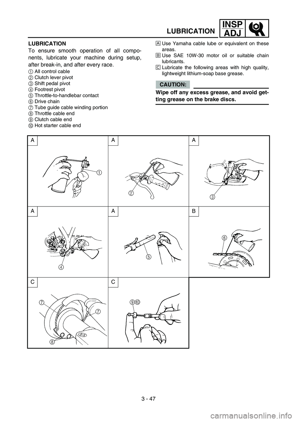
LUBRICATION
To ensure smooth operation of all compo-
nents, lubricate your machine during setup,
after break-in, and after every race.
1All control cable
2Clutch lever pivot
3Shift pedal pivot
4Footrest pivot
5Throttle-to-handlebar contact
6Drive chain
7Tube guide cable winding portion
8Throttle cable end
9Clutch cable end
0Hot starter cable endÈUse Yamaha cable lube or equivalent on these
areas.
ÉUse SAE 10W-30 motor oil or suitable chain
lubricants.
ÊLubricate the following areas with high quality,
lightweight lithium-soap base grease.
CAUTION:
Wipe off any excess grease, and avoid get-
ting grease on the brake discs.
AAA
AA
B
CC
Page 568 of 786
5 - 21
CHASFRONT BRAKE AND REAR BRAKE
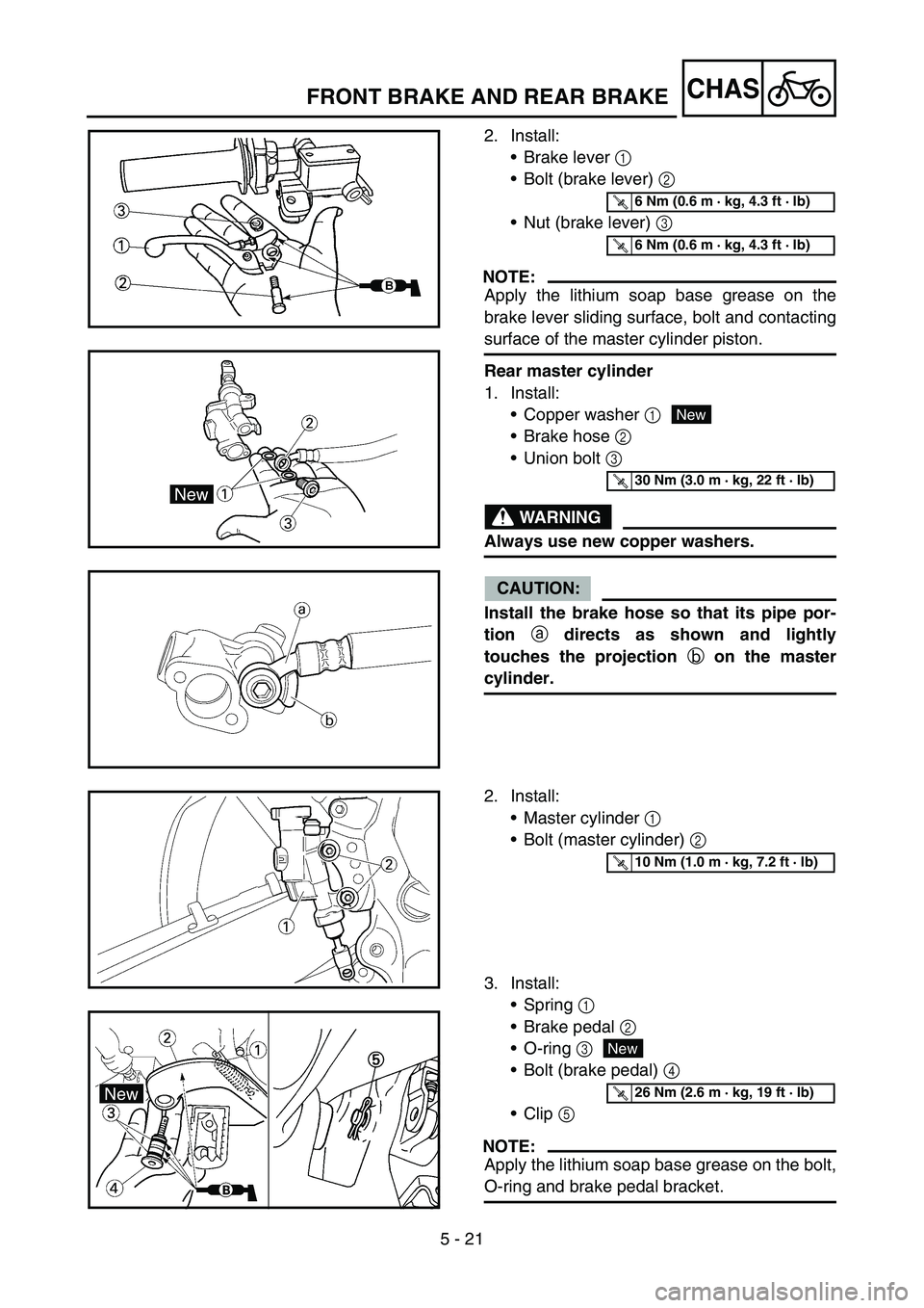
2. Install:
Brake lever 1
Bolt (brake lever) 2
Nut (brake lever) 3
NOTE:
Apply the lithium soap base grease on the
brake lever sliding surface, bolt and contacting
surface of the master cylinder piston.
Rear master cylinder
1. Install:
Copper washer 1
Brake hose 2
Union bolt 3
WARNING
Always use new copper washers.
CAUTION:
Install the brake hose so that its pipe por-
tion
a directs as shown and lightly
touches the projection
b on the master
cylinder.
T R..6 Nm (0.6 m · kg, 4.3 ft · lb)
T R..6 Nm (0.6 m · kg, 4.3 ft · lb)
New
T R..30 Nm (3.0 m · kg, 22 ft · lb)
2. Install:
Master cylinder 1
Bolt (master cylinder) 2
3. Install:
Spring 1
Brake pedal 2
O-ring 3
Bolt (brake pedal) 4
Clip 5
NOTE:
Apply the lithium soap base grease on the bolt,
O-ring and brake pedal bracket.
T R..10 Nm (1.0 m · kg, 7.2 ft · lb)
New
T R..26 Nm (2.6 m · kg, 19 ft · lb)
Page 570 of 786
5 - 22
CHASFRONT BRAKE AND REAR BRAKE
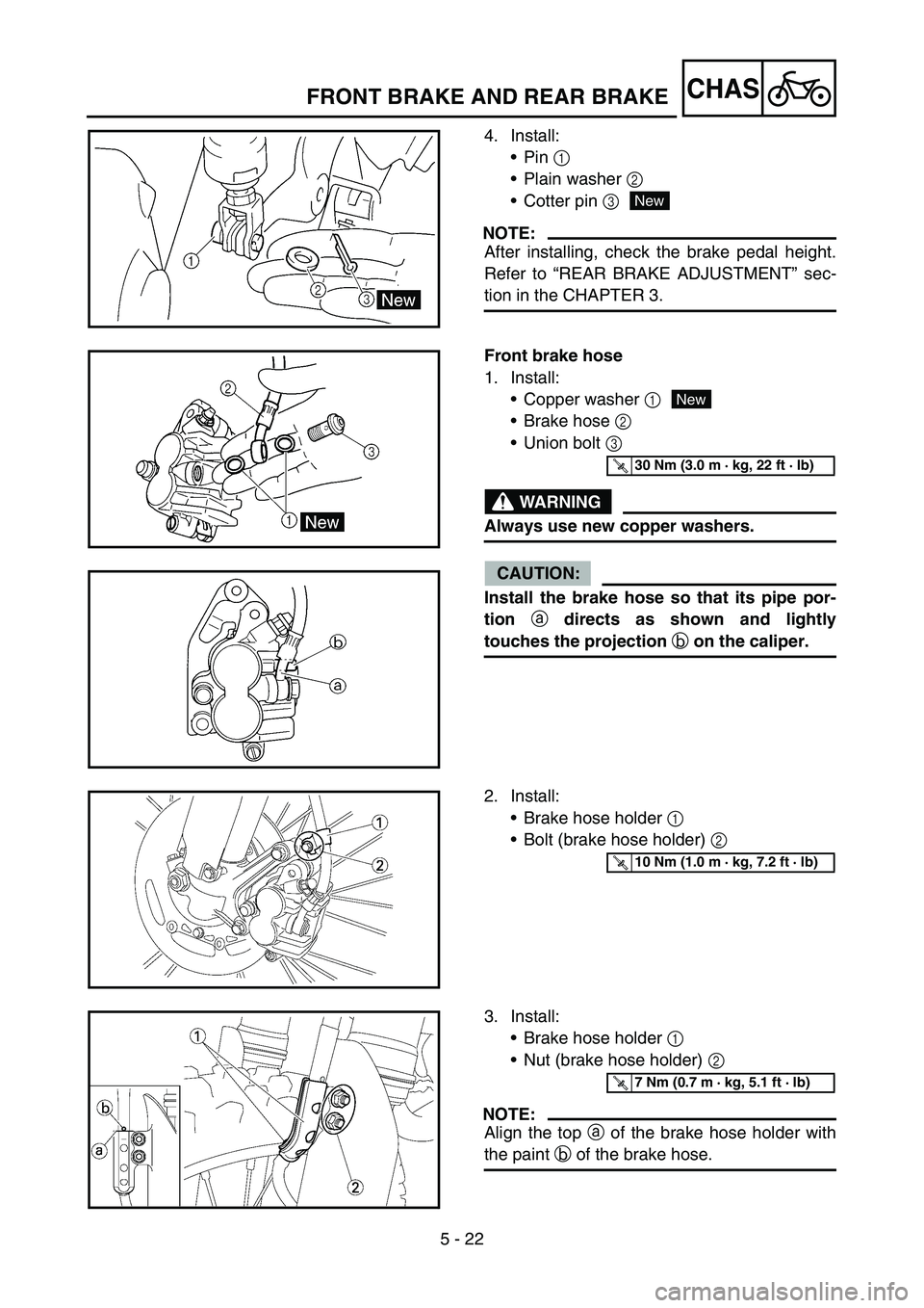
4. Install:
Pin 1
Plain washer 2
Cotter pin 3
NOTE:
After installing, check the brake pedal height.
Refer to “REAR BRAKE ADJUSTMENT” sec-
tion in the CHAPTER 3.
New
Front brake hose
1. Install:
Copper washer 1
Brake hose 2
Union bolt 3
WARNING
Always use new copper washers.
CAUTION:
Install the brake hose so that its pipe por-
tion
a directs as shown and lightly
touches the projection
b on the caliper.
New
T R..30 Nm (3.0 m · kg, 22 ft · lb)
2. Install:
Brake hose holder 1
Bolt (brake hose holder) 2
T R..10 Nm (1.0 m · kg, 7.2 ft · lb)
3. Install:
Brake hose holder 1
Nut (brake hose holder) 2
NOTE:
Align the top a of the brake hose holder with
the paint b of the brake hose.
T R..7 Nm (0.7 m · kg, 5.1 ft · lb)
Page 572 of 786
5 - 23
CHASFRONT BRAKE AND REAR BRAKE
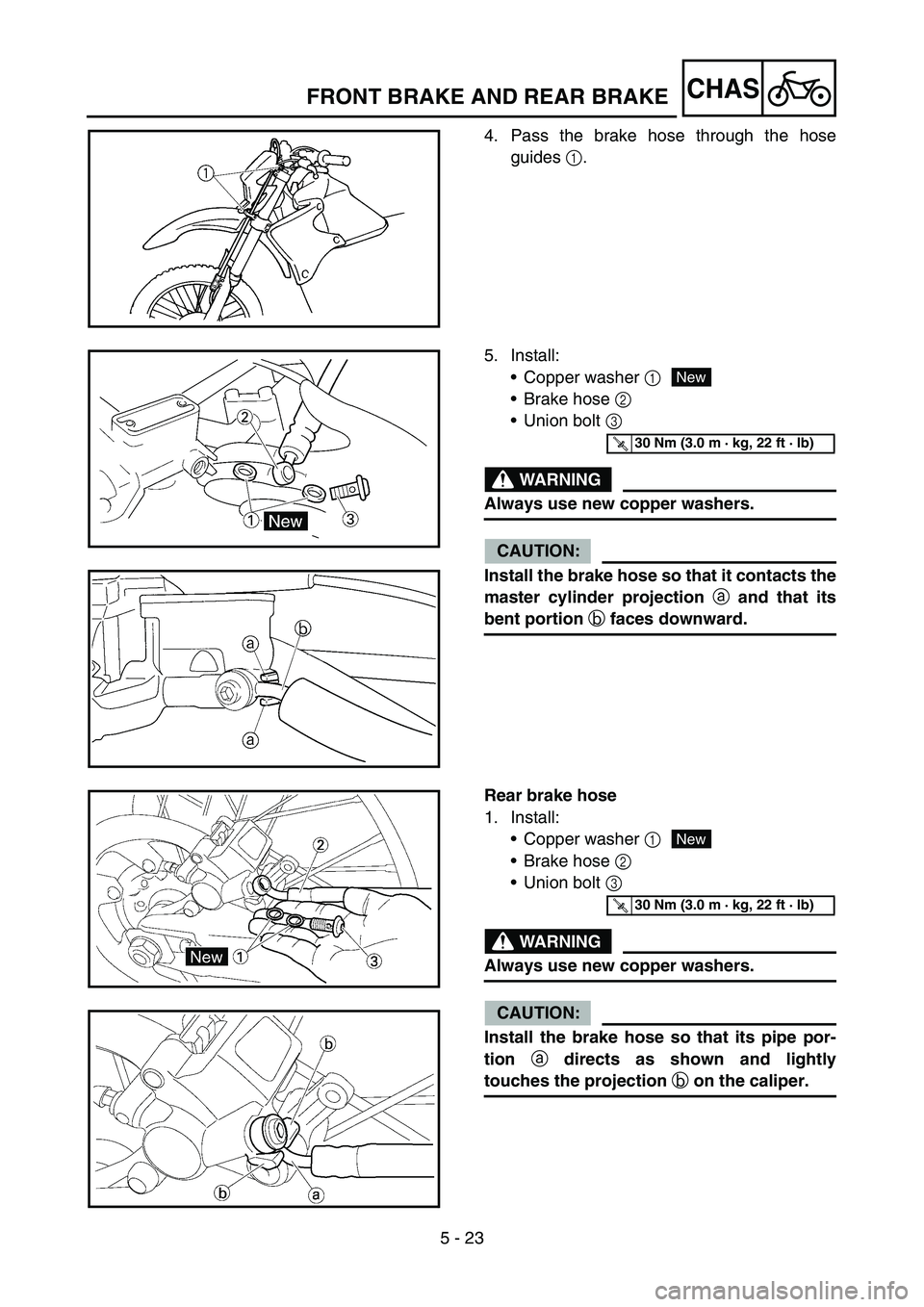
4. Pass the brake hose through the hose
guides 1.
5. Install:
Copper washer 1
Brake hose 2
Union bolt 3
WARNING
Always use new copper washers.
CAUTION:
Install the brake hose so that it contacts the
master cylinder projection
a and that its
bent portion
b faces downward.
New
T R..30 Nm (3.0 m · kg, 22 ft · lb)
Rear brake hose
1. Install:
Copper washer 1
Brake hose 2
Union bolt 3
WARNING
Always use new copper washers.
CAUTION:
Install the brake hose so that its pipe por-
tion
a directs as shown and lightly
touches the projection
b on the caliper.
New
T R..30 Nm (3.0 m · kg, 22 ft · lb)
Page 578 of 786
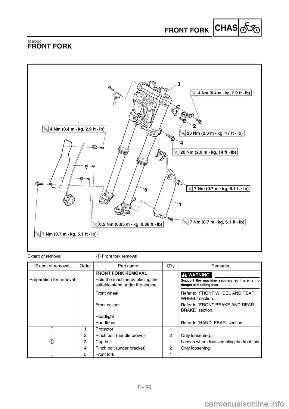
5 - 26
CHASFRONT FORK
EC550000
FRONT FORK
Extent of removal:
1 Front fork removal
Extent of removal Order Part name Q’ty Remarks
FRONT FORK REMOVAL
WARNING
Support the machine securely so there is nodanger of it falling over.
Preparation for removal Hold the machine by placing the
suitable stand under the engine.
Front wheel Refer to “FRONT WHEEL AND REAR
WHEEL” section.
Front caliper Refer to “FRONT BRAKE AND REAR
BRAKE” section.
Headlight
Handlebar Refer to “HANDLEBAR” section.
1 Protector 1
2 Pinch bolt (handle crown) 2 Only loosening.
3 Cap bolt 1 Loosen when disassembling the front fork.
4 Pinch bolt (under bracket) 2 Only loosening.
5 Front fork 1
1