engine YAMAHA WR 450F 2006 User Guide
[x] Cancel search | Manufacturer: YAMAHA, Model Year: 2006, Model line: WR 450F, Model: YAMAHA WR 450F 2006Pages: 786, PDF Size: 22.49 MB
Page 32 of 786
1 - 4
GEN
INFO
IMPORTANT INFORMATION
EC132000
ALL REPLACEMENT PARTS
1. We recommend to use Yamaha genuine
parts for all replacements. Use oil and/or
grease recommended by Yamaha for
assembly and adjustment.
EC133000
GASKETS, OIL SEALS AND O-RINGS
1. All gaskets, oil seals, and O-rings should
be replaced when an engine is overhauled.
All gasket surfaces, oil seal lips, and O-
rings must be cleaned.
2. Properly oil all mating parts and bearings
during reassembly. Apply grease to the oil
seal lips.
EC134000
LOCK WASHERS/PLATES AND COTTER
PINS
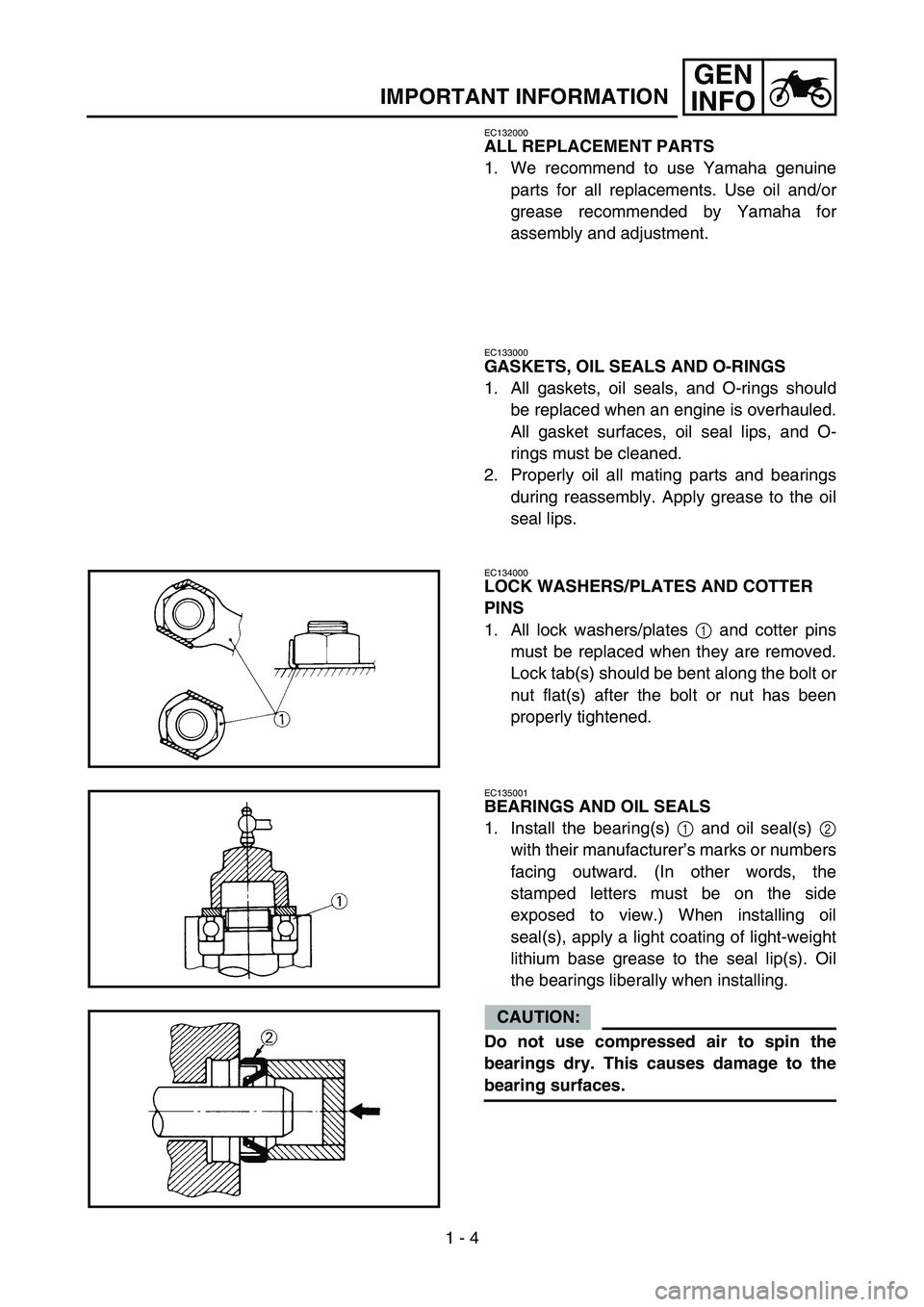
1. All lock washers/plates 1 and cotter pins
must be replaced when they are removed.
Lock tab(s) should be bent along the bolt or
nut flat(s) after the bolt or nut has been
properly tightened.
EC135001
BEARINGS AND OIL SEALS
1. Install the bearing(s) 1 and oil seal(s) 2
with their manufacturer’s marks or numbers
facing outward. (In other words, the
stamped letters must be on the side
exposed to view.) When installing oil
seal(s), apply a light coating of light-weight
lithium base grease to the seal lip(s). Oil
the bearings liberally when installing.
CAUTION:
Do not use compressed air to spin the
bearings dry. This causes damage to the
bearing surfaces.
Page 50 of 786
1 - 10
GEN
INFO
CONTROL FUNCTIONS
EC150000
CONTROL FUNCTIONS
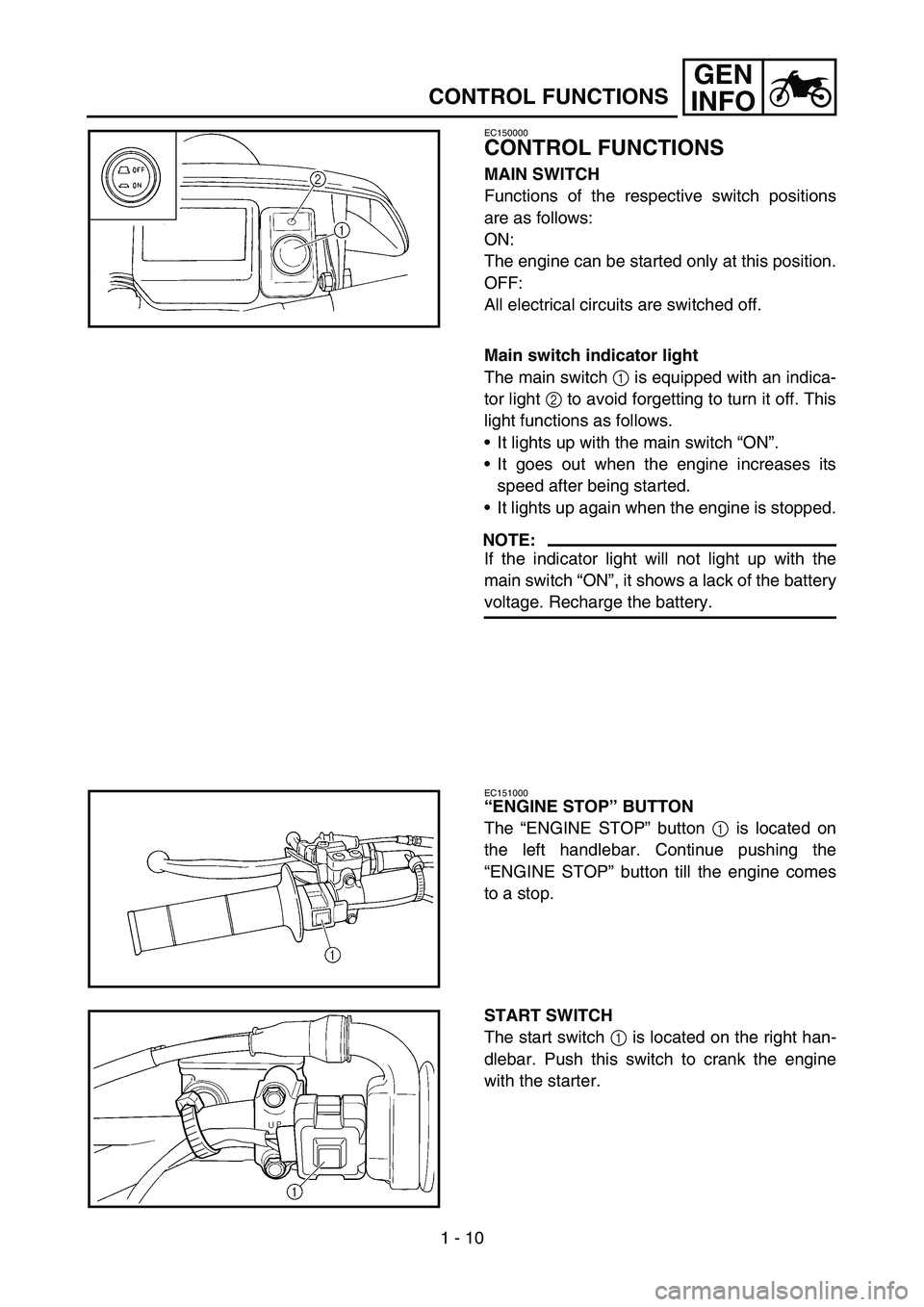
MAIN SWITCH
Functions of the respective switch positions
are as follows:
ON:
The engine can be started only at this position.
OFF:
All electrical circuits are switched off.
Main switch indicator light
The main switch 1 is equipped with an indica-
tor light 2 to avoid forgetting to turn it off. This
light functions as follows.
It lights up with the main switch “ON”.
It goes out when the engine increases its
speed after being started.
It lights up again when the engine is stopped.
NOTE:
If the indicator light will not light up with the
main switch “ON”, it shows a lack of the battery
voltage. Recharge the battery.
EC151000
“ENGINE STOP” BUTTON
The “ENGINE STOP” button 1 is located on
the left handlebar. Continue pushing the
“ENGINE STOP” button till the engine comes
to a stop.
START SWITCH
The start switch 1 is located on the right han-
dlebar. Push this switch to crank the engine
with the starter.
Page 51 of 786
GEN
INFO
BEDIENUNGSELEMENTE
UND DEREN FUNKTION
ZÜNDSCHALTER
Die einzelnen Zündschalterstellun-
gen sind nachfolgend beschrieben:
ON:
Nur in dieser Stellung kann der Motor
gestartet werden.
OFF:
Alle elektrischen Stromkreise sind
ausgeschaltet.
Zündschalter-Kontrollleuchte
Der Zündschalter 1 ist mit einer
Kontrollleuchte 2 versehen, die den
Fahrer daran erinnern soll, die Zün-
dung auszuschalten. Die Funktions-
weise ist nachfolgend beschrieben.
Leuchtet in der “ON”-Stellung des
Zündschalters.
Erlischt, wenn der Motor nach dem
Anlassen eine gewisse Drehzahl
erreicht.
Leuchtet erneut auf, wenn der
Motor abgestellt wird.
HINWEIS:
Falls die Kontrollleuchte beim Stellen
des Zündschalters auf “ON” nicht
aufleuchtet, ist die Batteriespannung
zu niedrig. In diesem Fall die Batterie
laden.
MOTORSTOPPSCHALTER
“ENGINE STOP”
Der Motorstoppschalter “ENGINE
STOP” 1 befindet sich links am Len-
ker. Den Motorstoppschalter
“ENGINE STOP” gedrückt halten, bis
der Motor stoppt.
STARTERSCHALTER
Der Starterschalter 1 befindet sich
rechts am Lenker. Diesen Schalter
drücken, um den Motor anzulassen.
FONCTIONS DES
COMMANDES
CONTACTEUR A CLE
Les fonctions correspondant aux diffé-
rentes positions du contacteur sont les
suivantes:
ON:
seule position permettant le démarrage
du moteur.
OFF:
tous les circuits électriques sont coupés.
Témoin de l’interrupteur à clé
L’interrupteur à clé 1 est équipé d’un
témoin 2 afin de ne pas oublier de le
couper. Ce témoin fonctionne de la
manière suivante.
Il s’allume lorsque l’interrupteur à clé
est en position “ON”.
Il s’éteint lorsque le moteur monte en
régime après le démarrage.
Il se rallume lorsque le moteur est
coupé.
N.B.:
Si le témoin ne s’allume pas lorsque
l’interrupteur à clé est sur “ON”, c’est
que la tension de la batterie est trop fai-
ble. Recharger la batterie.
BOUTON “ENGINE STOP”
Le bouton “ENGINE STOP” 1 est situé
sur la partie gauche du guidon. Garder ce
bouton enfoncé jusqu’à ce que le moteur
s’arrête.
CONTACTEUR DU DEMARREUR
Le contacteur du démarreur 1 est situé
sur la partie droite du guidon. Appuyer
sur ce contacteur pour lancer le moteur à
l’aide du démarreur.
FUNCIONES DE LOS
MANDOS
INTERRUPTOR PRINCIPAL
Las funciones de las diferentes posicio-
nes del interruptor son las siguientes:
ON:
El motor solo se puede poner en marcha
en esta posición.
OFF:
Todos los circuitos eléctricos desconec-
tados.
Luz indicadora del interruptor princi-
pal
El interruptor principal 1 está provisto
de una luz indicadora 2 para no olvidar
desconectarlo. Dicha luz funciona del
modo siguiente.
Se ilumina cuando se sitúa el interrup-
tor principal en “ON”.
Se apaga cuando el régimen del motor
aumenta después del arranque.
Se vuelve a encender cuando se para
el motor.
NOTA:
Si la luz indicadora no se ilumina cuando
se sitúa el interruptor principal en “ON”
significa que la tensión de la batería está
baja. Recargue la batería.
BOTÓN “ENGINE STOP” (PARO
DEL MOTOR)
El botón “ENGINE STOP” 1 se
encuentra en el lado izquierdo del mani-
llar. Mantenga pulsado el botón
“ENGINE STOP” hasta que se pare el
motor.
INTERRUPTOR DE ARRANQUE
El interruptor de arranque 1 se encuen-
tra en el lado derecho del manillar. Pulse
este interruptor para poner en marcha el
motor con el motor de arranque.
FONCTIONS DES COMMANDES
BEDIENUNGSELEMENTE UND DEREN FUNKTION
FUNCIONES DE LOS MANDOS
1 - 10
Page 52 of 786
1 - 11
GEN
INFO
CONTROL FUNCTIONS
EC152000
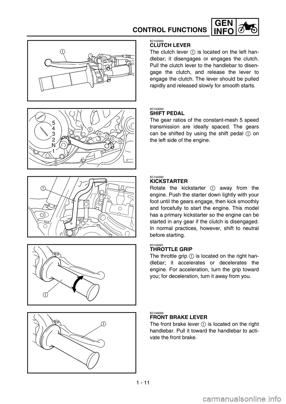
CLUTCH LEVER
The clutch lever 1 is located on the left han-
dlebar; it disengages or engages the clutch.
Pull the clutch lever to the handlebar to disen-
gage the clutch, and release the lever to
engage the clutch. The lever should be pulled
rapidly and released slowly for smooth starts.
EC153000
SHIFT PEDAL
The gear ratios of the constant-mesh 5 speed
transmission are ideally spaced. The gears
can be shifted by using the shift pedal 1 on
the left side of the engine.
EC154000
KICKSTARTER
Rotate the kickstarter 1 away from the
engine. Push the starter down lightly with your
foot until the gears engage, then kick smoothly
and forcefully to start the engine. This model
has a primary kickstarter so the engine can be
started in any gear if the clutch is disengaged.
In normal practices, however, shift to neutral
before starting.
1
EC155001
THROTTLE GRIP
The throttle grip 1 is located on the right han-
dlebar; it accelerates or decelerates the
engine. For acceleration, turn the grip toward
you; for deceleration, turn it away from you.
EC156000
FRONT BRAKE LEVER
The front brake lever 1 is located on the right
handlebar. Pull it toward the handlebar to acti-
vate the front brake.
Page 54 of 786
1 - 12
GEN
INFO
CONTROL FUNCTIONS
EC157000
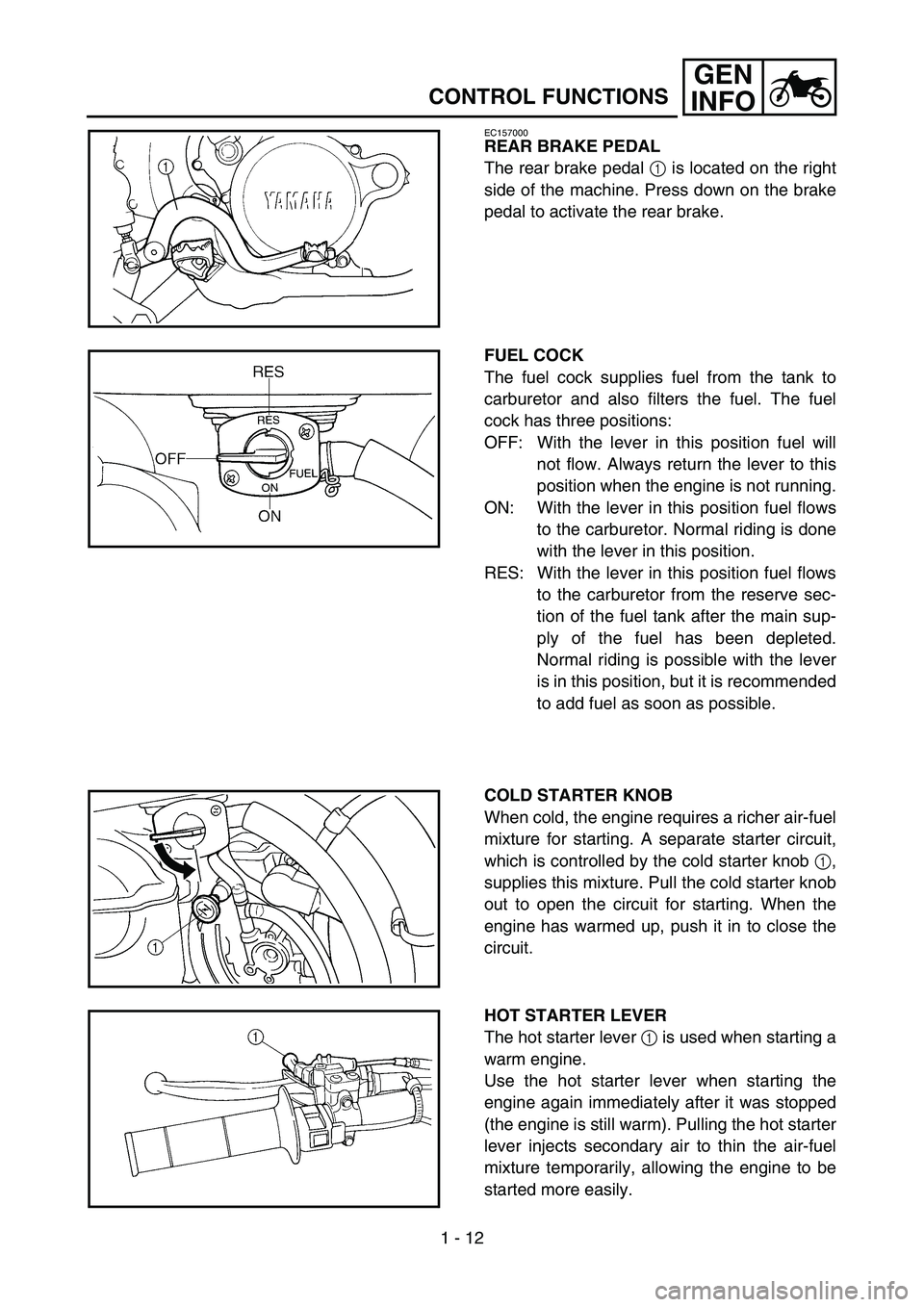
REAR BRAKE PEDAL
The rear brake pedal 1 is located on the right
side of the machine. Press down on the brake
pedal to activate the rear brake.
FUEL COCK
The fuel cock supplies fuel from the tank to
carburetor and also filters the fuel. The fuel
cock has three positions:
OFF: With the lever in this position fuel will
not flow. Always return the lever to this
position when the engine is not running.
ON: With the lever in this position fuel flows
to the carburetor. Normal riding is done
with the lever in this position.
RES: With the lever in this position fuel flows
to the carburetor from the reserve sec-
tion of the fuel tank after the main sup-
ply of the fuel has been depleted.
Normal riding is possible with the lever
is in this position, but it is recommended
to add fuel as soon as possible.
COLD STARTER KNOB
When cold, the engine requires a richer air-fuel
mixture for starting. A separate starter circuit,
which is controlled by the cold starter knob 1,
supplies this mixture. Pull the cold starter knob
out to open the circuit for starting. When the
engine has warmed up, push it in to close the
circuit.
HOT STARTER LEVER
The hot starter lever 1 is used when starting a
warm engine.
Use the hot starter lever when starting the
engine again immediately after it was stopped
(the engine is still warm). Pulling the hot starter
lever injects secondary air to thin the air-fuel
mixture temporarily, allowing the engine to be
started more easily.
Page 72 of 786
1 - 21
GEN
INFO
FUEL
Always use the recommended fuel as stated
below. Also, be sure to use new gasoline the
day of a race.
CAUTION:
Use only unleaded gasoline. The use of
leaded gasoline will cause severe damage
to the engine internal parts such as valves,
piston rings, and exhaust system, etc.
NOTE:
If knocking or pinging occurs, use a different
brand of gasoline or higher octane grade.
WARNING
For refueling, be sure to stop the engine
and use enough care not to spill any fuel.
Also be sure to avoid refueling close to a
fire.
Refuel after the engine, exhaust pipe, etc.
have cooled off.
Recommended fuel:
Premium unleaded gasoline
only with a research octane
number of 95 or higher.
FUEL
Page 74 of 786
1 - 22
GEN
INFO
STARTING AND BREAK-IN
STARTING AND BREAK-IN
WARNING
Never start or run the engine in a closed
area. The exhaust fumes are poisonous;
they can cause loss of consciousness and
death in a very short time. Always operate
the machine in a well-ventilated area.
CAUTION:
The carburetor on this machine has a
built-in accelerator pump. Therefore,
when starting the engine, do not operate
the throttle or the spark plug will foul.
Unlike a two-stroke engine, this engine
cannot be kick started when the throttle is
open because the kickstarter may kick
back. Also, if the throttle is open the air/
fuel mixture may be too lean for the
engine to start.
Before starting the machine, perform the
checks in the pre-operation check list.
AIR FILTER MAINTENANCE
According to “AIR FILTER CLEANING” section
in the CHAPTER 3, apply the foam-air-filter oil
or its equivalent to the element. (Excess oil in
the element may adversely affect engine start-
ing.)
STARTING A COLD ENGINE
NOTE:
This model is equipped with an ignition circuit
cut-off system. The engine can be started
under the following conditions.
When the transmission is in neutral.
When the clutch is disengaged with the
transmission in any position. However, it is
recommended to shift into neutral before
starting the engine.
1. Inspect the coolant level.
2. Turn the fuel cock to “ON”.
3. Push the main switch to “ON”.
4. Shift the transmission into neutral.
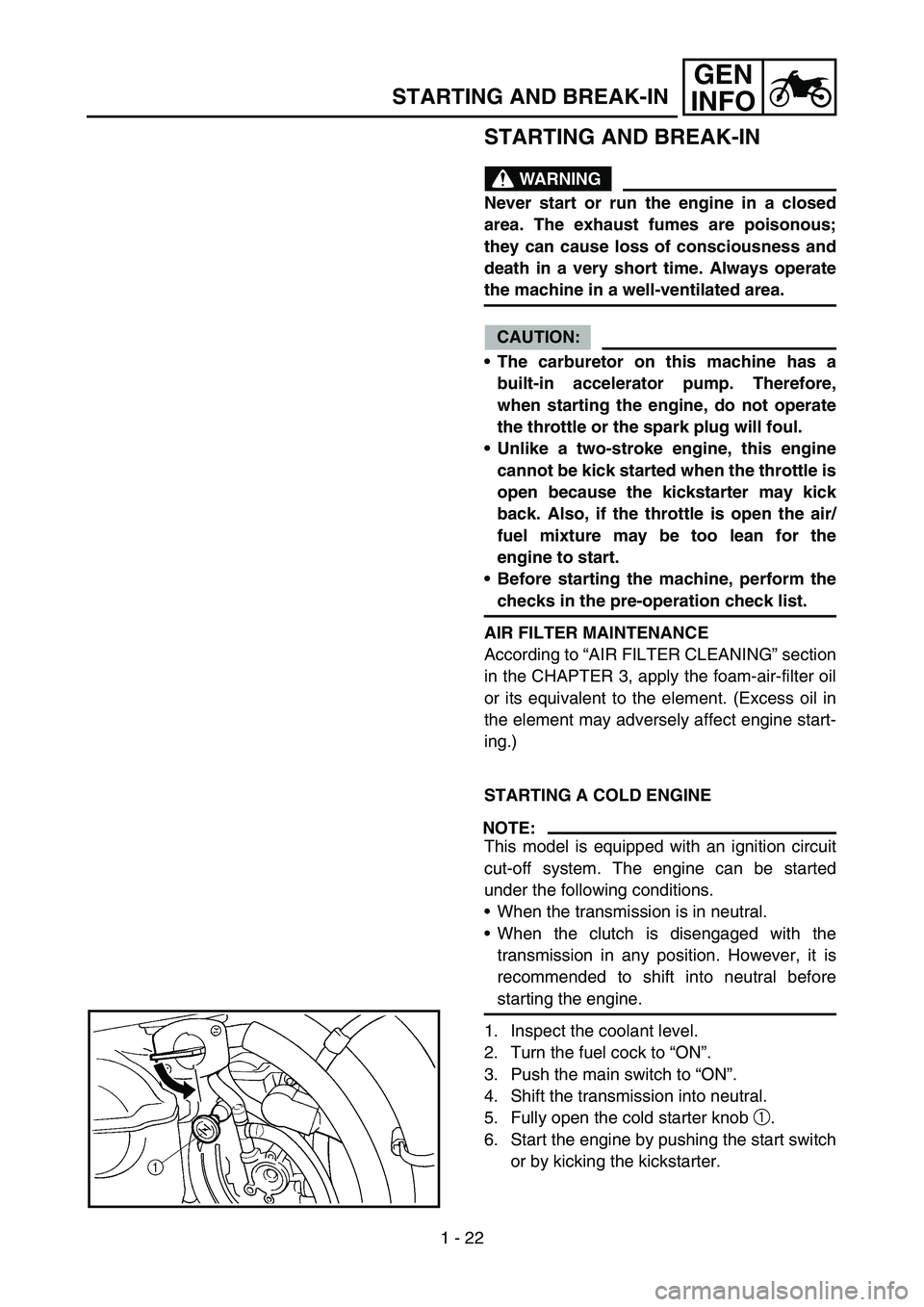
5. Fully open the cold starter knob 1.
6. Start the engine by pushing the start switch
or by kicking the kickstarter.
Page 76 of 786
1 - 23
GEN
INFO
STARTING AND BREAK-IN
NOTE:
If the engine fails to start by pushing the start
switch, release the switch, wait a few seconds,
and then try again. Each starting attempt
should be as short as possible to preserve the
battery. Do not crank the engine more than
10 seconds on any one attempt. If the engine
does not start with the starter motor, try using
the kickstarter.
WARNING
If the starter motor will not turn when
pushing the start switch, stop pushing it
immediately and kick start the engine in
order to avoid the load on the motor.
Do not open the throttle while kicking the
kickstarter. Otherwise, the kickstarter
may kick back.
7. Return the cold starter knob to its original
position and run the engine at 3,000 ~
5,000 r/min for 1 or 2 minutes.
NOTE:
Since this model is equipped with an accelera-
tor pump, if the engine is raced (the throttle
opened and closed), the air/fuel mixture will be
too rich and the engine may stall. Also unlike a
two-stroke engine, this model can idle.
CAUTION:
Do not warm up the engine for extended
periods of time.
Page 78 of 786
1 - 24
GEN
INFO
STARTING AND BREAK-IN
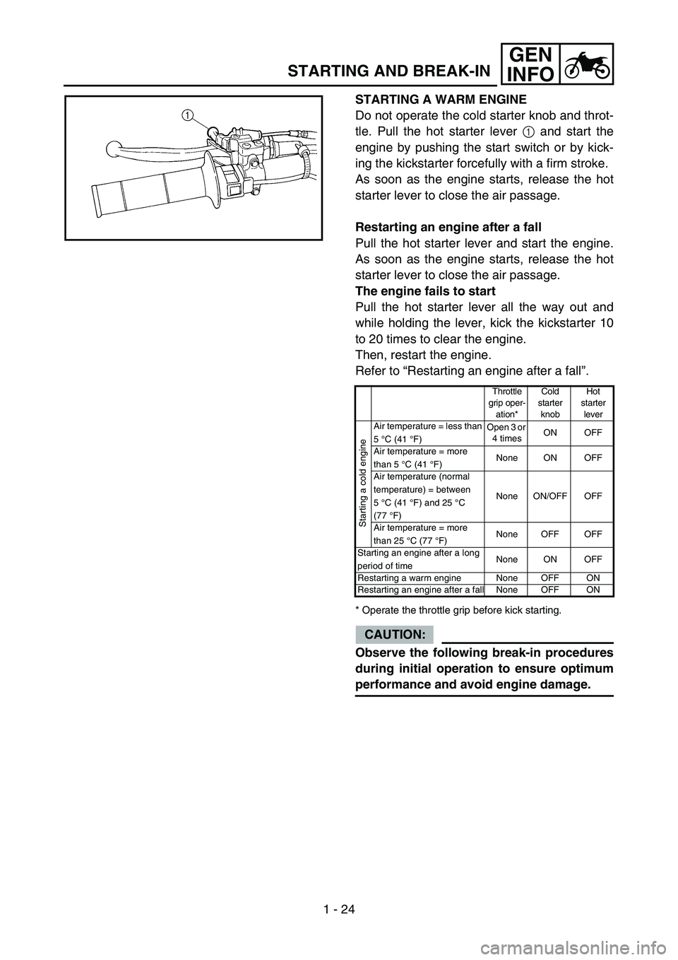
STARTING A WARM ENGINE
Do not operate the cold starter knob and throt-
tle. Pull the hot starter lever 1 and start the
engine by pushing the start switch or by kick-
ing the kickstarter forcefully with a firm stroke.
As soon as the engine starts, release the hot
starter lever to close the air passage.
Restarting an engine after a fall
Pull the hot starter lever and start the engine.
As soon as the engine starts, release the hot
starter lever to close the air passage.
The engine fails to start
Pull the hot starter lever all the way out and
while holding the lever, kick the kickstarter 10
to 20 times to clear the engine.
Then, restart the engine.
Refer to “Restarting an engine after a fall”.
* Operate the throttle grip before kick starting.
CAUTION:
Observe the following break-in procedures
during initial operation to ensure optimum
performance and avoid engine damage.
Throttle
grip oper-
ation*Cold
starter
knobHot
starter
lever
Starting a cold engine
Air temperature = less than
5 °C (41 °F)Open 3 or
4 timesON OFF
Air temperature = more
than 5 °C (41 °F)None ON OFF
Air temperature (normal
temperature) = between
5°C (41°F) and 25 °C
(77°F)None ON/OFF OFF
Air temperature = more
than 25 °C (77 °F)None OFF OFF
Starting an engine after a long
period of timeNone ON OFF
Restarting a warm engine None OFF ON
Restarting an engine after a fall None OFF ON
Page 80 of 786
1 - 25
GEN
INFO
BREAK-IN PROCEDURES
1. Before starting the engine, fill the fuel tank
with the fuel.
2. Perform the pre-operation checks on the
machine.
3. Start and warm up the engine. Check the
idle speed, and check the operation of the
controls and the “ENGINE STOP” button.
Then, restart the engine and check its
operation within no more than 5 minutes
after it is restarted.
4. Operate the machine in the lower gears at
moderate throttle openings for five to eight
minutes.
5. Check how the engine runs when the
machine is ridden with the throttle 1/4 to 1/2
open (low to medium speed) for about one
hour.
6. Restart the engine and check the operation
of the machine throughout its entire operat-
ing range. Restart the machine and oper-
ate it for about 10 to 15 more minutes. The
machine will now be ready to race.
CAUTION:
After the break-in or before each race,
you must check the entire machine for
loose fittings and fasteners as per
“TORQUE-CHECK POINTS”.
Tighten all such fasteners as required.
When any of the following parts have
been replaced, they must be broken in.
CYLINDER AND CRANKSHAFT:
About one hour of break-in operation is
necessary.
PISTON, RING, VALVES, CAMSHAFTS
AND GEARS:
These parts require about 30 minutes of
break-in operation at half-throttle or less.
Observe the condition of the engine care-
fully during operation.
STARTING AND BREAK-IN