engine YAMAHA WR 450F 2006 Repair Manual
[x] Cancel search | Manufacturer: YAMAHA, Model Year: 2006, Model line: WR 450F, Model: YAMAHA WR 450F 2006Pages: 786, PDF Size: 22.49 MB
Page 362 of 786
4 - 23
ENGCAMSHAFTS
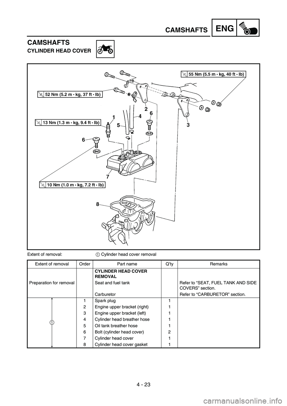
CAMSHAFTS
CYLINDER HEAD COVER
Extent of removal:
1 Cylinder head cover removal
Extent of removal Order Part name Q’ty Remarks
CYLINDER HEAD COVER
REMOVAL
Preparation for removal Seat and fuel tank Refer to “SEAT, FUEL TANK AND SIDE
COVERS” section.
Carburetor Refer to “CARBURETOR” section.
1 Spark plug 1
2 Engine upper bracket (right) 1
3 Engine upper bracket (left) 1
4 Cylinder head breather hose 1
5 Oil tank breather hose 1
6 Bolt (cylinder head cover) 2
7 Cylinder head cover 1
8 Cylinder head cover gasket 1
1
Page 372 of 786

4 - 28
ENGCAMSHAFTS
Decompression system
1. Check:
Decompression system
Checking steps:
Check that the decompressor cam 1
moves smoothly.
Check that the decompressor lever pin 2
projects from the camshaft.
Timing chain tensioner
1. Check:
While pressing the tensioner rod lightly
with fingers, use a thin screwdriver 1
and wind the tensioner rod up fully clock-
wise.
When releasing the screwdriver by press-
ing lightly with fingers, make sure that the
tensioner rod will come out smoothly.
If not, replace the tensioner assembly.
ASSEMBLY AND INSTALLATION
1. Install:
Exhaust camshaft 1
Intake camshaft 2
Installation steps:
Turn the crankshaft counterclockwise until
the “I” mark a on the rotor is aligned with
the stationary pointer b on the crankcase
cover.
NOTE:
Apply the molybdenum disulfide oil on the
camshafts.
Apply the engine oil on the decompression
system.
Page 404 of 786
4 - 44
ENGVALVES AND VALVE SPRINGS
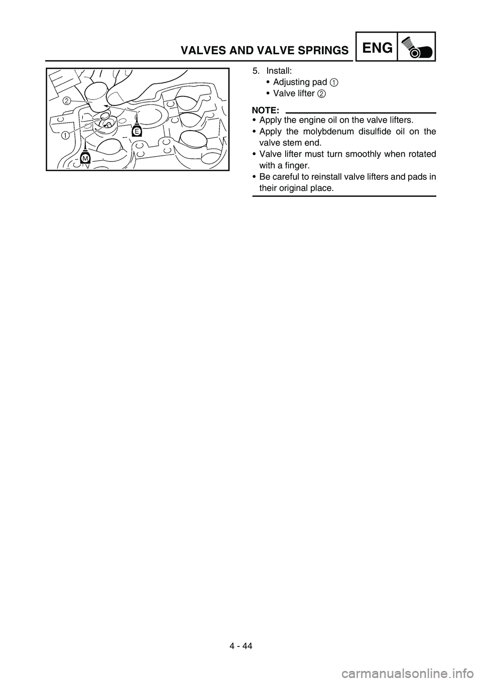
5. Install:
Adjusting pad 1
Valve lifter 2
NOTE:
Apply the engine oil on the valve lifters.
Apply the molybdenum disulfide oil on the
valve stem end.
Valve lifter must turn smoothly when rotated
with a finger.
Be careful to reinstall valve lifters and pads in
their original place.
Page 414 of 786
4 - 49
ENGCYLINDER AND PISTON
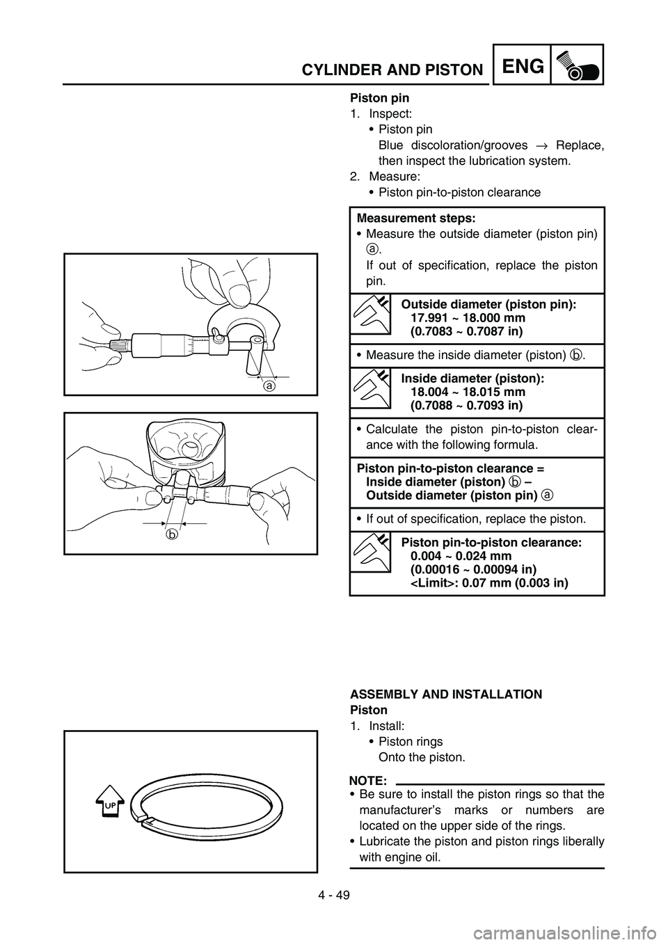
Piston pin
1. Inspect:
Piston pin
Blue discoloration/grooves → Replace,
then inspect the lubrication system.
2. Measure:
Piston pin-to-piston clearance
ASSEMBLY AND INSTALLATION
Piston
1. Install:
Piston rings
Onto the piston.
NOTE:
Be sure to install the piston rings so that the
manufacturer’s marks or numbers are
located on the upper side of the rings.
Lubricate the piston and piston rings liberally
with engine oil. Measurement steps:
Measure the outside diameter (piston pin)
a.
If out of specification, replace the piston
pin.
Outside diameter (piston pin):
17.991 ~ 18.000 mm
(0.7083 ~ 0.7087 in)
Measure the inside diameter (piston) b.
Inside diameter (piston):
18.004 ~ 18.015 mm
(0.7088 ~ 0.7093 in)
Calculate the piston pin-to-piston clear-
ance with the following formula.
Piston pin-to-piston clearance =
Inside diameter (piston)
b –
Outside diameter (piston pin)
a
If out of specification, replace the piston.
Piston pin-to-piston clearance:
0.004 ~ 0.024 mm
(0.00016 ~ 0.00094 in)
Page 416 of 786
4 - 50
ENGCYLINDER AND PISTON
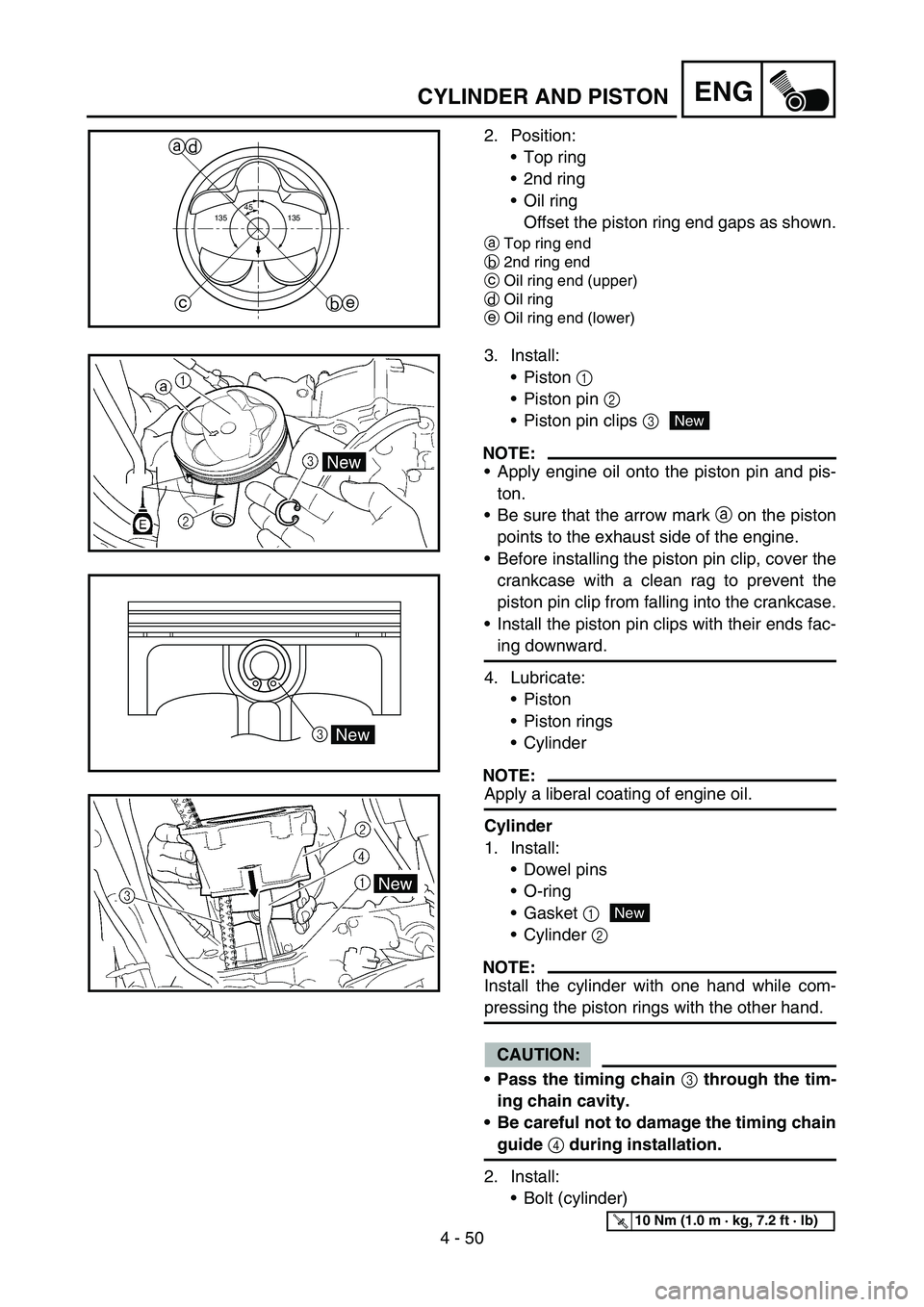
2. Position:
Top ring
2nd ring
Oil ring
Offset the piston ring end gaps as shown.
aTop ring end
b2nd ring end
cOil ring end (upper)
dOil ring
eOil ring end (lower)
45
135 135
a
b ced
3. Install:
Piston 1
Piston pin 2
Piston pin clips 3
NOTE:
Apply engine oil onto the piston pin and pis-
ton.
Be sure that the arrow mark
a on the piston
points to the exhaust side of the engine.
Before installing the piston pin clip, cover the
crankcase with a clean rag to prevent the
piston pin clip from falling into the crankcase.
Install the piston pin clips with their ends fac-
ing downward.
4. Lubricate:
Piston
Piston rings
Cylinder
NOTE:
Apply a liberal coating of engine oil.
Cylinder
1. Install:
Dowel pins
O-ring
Gasket 1
Cylinder 2
NOTE:
Install the cylinder with one hand while com-
pressing the piston rings with the other hand.
CAUTION:
Pass the timing chain
3 through the tim-
ing chain cavity.
Be careful not to damage the timing chain
guide
4 during installation.
2. Install:
Bolt (cylinder)
3New
New
New
T R..10 Nm (1.0 m · kg, 7.2 ft · lb)
Page 418 of 786
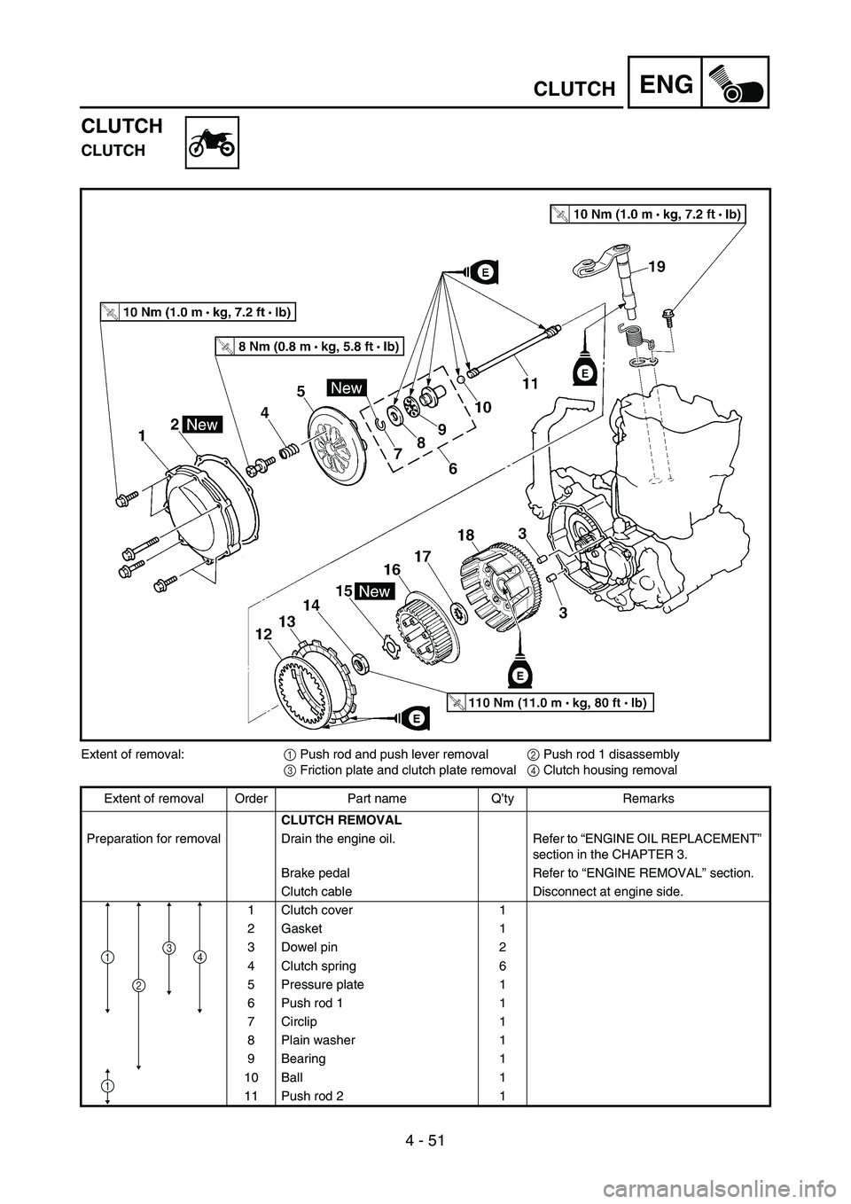
4 - 51
ENGCLUTCH
CLUTCH
CLUTCH
Extent of removal:
1 Push rod and push lever removal
2 Push rod 1 disassembly
3 Friction plate and clutch plate removal
4 Clutch housing removal
Extent of removal Order Part name Q’ty Remarks
CLUTCH REMOVAL
Preparation for removal Drain the engine oil. Refer to “ENGINE OIL REPLACEMENT”
section in the CHAPTER 3.
Brake pedal Refer to “ENGINE REMOVAL” section.
Clutch cable Disconnect at engine side.
1 Clutch cover 1
2 Gasket 1
3 Dowel pin 2
4 Clutch spring 6
5 Pressure plate 1
6 Push rod 1 1
7 Circlip 1
8 Plain washer 1
9 Bearing 1
10 Ball 1
11 Push rod 2 1
1
2
34
1
Page 426 of 786
4 - 55
ENGCLUTCH
EC4A5000
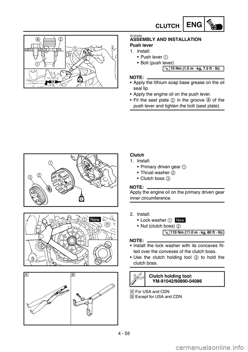
ASSEMBLY AND INSTALLATION
Push lever
1. Install:
Push lever 1
Bolt (push lever)
NOTE:
Apply the lithium soap base grease on the oil
seal lip.
Apply the engine oil on the push lever.
Fit the seat plate 2 in the groove a of the
push lever and tighten the bolt (seat plate).
T R..10 Nm (1.0 m · kg, 7.2 ft · lb)
Clutch
1. Install:
Primary driven gear 1
Thrust washer 2
Clutch boss 3
NOTE:
Apply the engine oil on the primary driven gear
inner circumference.
2. Install:
Lock washer 1
Nut (clutch boss) 2
NOTE:
Install the lock washer with its concaves fit-
ted over the convexes of the clutch boss.
Use the clutch holding tool 3 to hold the
clutch boss.
ÈFor USA and CDN
ÉExcept for USA and CDN
Clutch holding tool:
YM-91042/90890-04086
New
T R..110 Nm (11.0 m · kg, 80 ft · lb)
ÈÉ
Page 428 of 786
![YAMAHA WR 450F 2006 Repair Manual 4 - 56
ENGCLUTCH
3. Bend the lock washer 1 tab.
4. Install:
Friction plate 1
Clutch plate 1
[t = 2.0 mm (0.079 in)] 2
Clutch plate 2
[t = 1.6 mm (0.063 in)] 3
NOTE:
Install the clutch plates YAMAHA WR 450F 2006 Repair Manual 4 - 56
ENGCLUTCH
3. Bend the lock washer 1 tab.
4. Install:
Friction plate 1
Clutch plate 1
[t = 2.0 mm (0.079 in)] 2
Clutch plate 2
[t = 1.6 mm (0.063 in)] 3
NOTE:
Install the clutch plates](/img/51/52482/w960_52482-427.png)
4 - 56
ENGCLUTCH
3. Bend the lock washer 1 tab.
4. Install:
Friction plate 1
Clutch plate 1
[t = 2.0 mm (0.079 in)] 2
Clutch plate 2
[t = 1.6 mm (0.063 in)] 3
NOTE:
Install the clutch plates and friction plates
alternately on the clutch boss, starting with a
friction plate and ending with a friction plate.
Apply the engine oil on the friction plates and
clutch plates.
Check the clutch plate for thickness and
install 4 thicker ones a on the engine side
and 3 thinner ones b on the outside.
ab
5. Install:
Bearing 1
Plain washer 2
Circlip 3
To push rod 1 4.
NOTE:
Apply the engine oil on the bearing and plain
washer.
New
6. Install:
Push rod 2 1
Ball 2
Push rod 1 3
NOTE:
Apply the engine oil on the push rod 1, 2 and
ball.
Page 432 of 786
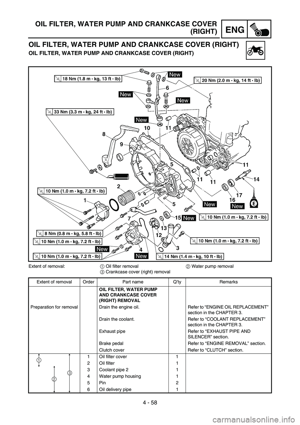
4 - 58
ENG
OIL FILTER, WATER PUMP AND CRANKCASE COVER
(RIGHT)
OIL FILTER, WATER PUMP AND CRANKCASE COVER (RIGHT)
OIL FILTER, WATER PUMP AND CRANKCASE COVER (RIGHT)
Extent of removal:
1 Oil filter removal
2 Water pump removal
3 Crankcase cover (right) removal
Extent of removal Order Part name Q’ty Remarks
OIL FILTER, WATER PUMP
AND CRANKCASE COVER
(RIGHT) REMOVAL
Preparation for removal Drain the engine oil. Refer to “ENGINE OIL REPLACEMENT”
section in the CHAPTER 3.
Drain the coolant. Refer to “COOLANT REPLACEMENT”
section in the CHAPTER 3.
Exhaust pipe Refer to “EXHAUST PIPE AND
SILENCER” section.
Brake pedal Refer to “ENGINE REMOVAL” section.
Clutch cover Refer to “CLUTCH” section.
1 Oil filter cover 1
2 Oil filter 1
3 Coolant pipe 2 1
4 Water pump housing 1
5Pin 2
6 Oil delivery pipe 1
1
2
3
Page 440 of 786

4 - 62
ENG
OIL FILTER, WATER PUMP AND CRANKCASE COVER
(RIGHT)
EC4G5220
Impeller shaft
1. Install:
Impeller shaft 1
Plain washer 2
Impeller 3
NOTE:
Take care so that the oil seal lip is not dam-
aged or the spring does not slip off its posi-
tion.
When installing the impeller shaft, apply the
engine oil on the oil seal lip, bearing and
impeller shaft. And install the shaft while
turning it.
Hold the impeller shaft on its width across
the flats a with spanners, etc. and install the
impeller.
T R..14 Nm (1.4 m · kg, 10 ft · lb)
Crankcase cover (right)
1. Install:
Dowel pin 1
O-ring 2
Collar 3
Gasket 4
New
New
2. Install:
Crankcase cover (right) 1
Bolt
NOTE:
Apply the engine oil on the impeller shaft
end.
When installing the crankcase cover onto the
crankcase, be sure that the impeller shaft
end 2 aligns with the balancer end slot 3.
Tighten the bolts in stage, using a crisscross
pattern.
T R..10 Nm (1.0 m · kg, 7.2 ft · lb)