check oil YAMAHA WR 450F 2006 Owners Manual
[x] Cancel search | Manufacturer: YAMAHA, Model Year: 2006, Model line: WR 450F, Model: YAMAHA WR 450F 2006Pages: 786, PDF Size: 22.49 MB
Page 39 of 786
GEN
INFO
1 - 8
SPECIAL TOOLS
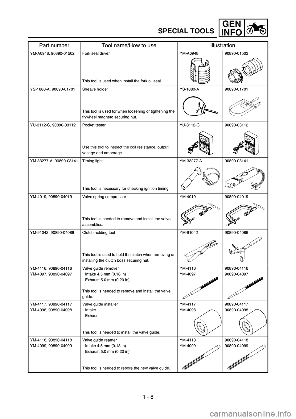
YM-A0948, 90890-01502 Fork seal driver
This tool is used when install the fork oil seal.YM-A0948 90890-01502
YS-1880-A, 90890-01701 Sheave holder
This tool is used for when loosening or tightening the
flywheel magneto securing nut.YS-1880-A 90890-01701
YU-3112-C, 90890-03112 Pocket tester
Use this tool to inspect the coil resistance, output
voltage and amperage.YU-3112-C 90890-03112
YM-33277-A, 90890-03141 Timing light
This tool is necessary for checking ignition timing.YM-33277-A 90890-03141
YM-4019, 90890-04019 Valve spring compressor
This tool is needed to remove and install the valve
assemblies.YM-4019 90890-04019
YM-91042, 90890-04086 Clutch holding tool
This tool is used to hold the clutch when removing or
installing the clutch boss securing nut.YM-91042 90890-04086
YM-4116, 90890-04116
YM-4097, 90890-04097Valve guide remover
Intake 4.5 mm (0.18 in)
Exhaust 5.0 mm (0.20 in)
This tool is needed to remove and install the valve
guide.YM-4116
YM-409790890-04116
90890-04097
YM-4117, 90890-04117
YM-4098, 90890-04098Valve guide installer
Intake
Exhaust
This tool is needed to install the valve guide.YM-4117
YM-409890890-04117
90890-04098
YM-4118, 90890-04118
YM-4099, 90890-04099Valve guide reamer
Intake 4.5 mm (0.18 in)
Exhaust 5.0 mm (0.20 in)
This tool is needed to rebore the new valve guide.YM-4118
YM-4099 90890-04118
90890-04099
Part number Tool name/How to use Illustration
Page 74 of 786
1 - 22
GEN
INFO
STARTING AND BREAK-IN
STARTING AND BREAK-IN
WARNING
Never start or run the engine in a closed
area. The exhaust fumes are poisonous;
they can cause loss of consciousness and
death in a very short time. Always operate
the machine in a well-ventilated area.
CAUTION:
The carburetor on this machine has a
built-in accelerator pump. Therefore,
when starting the engine, do not operate
the throttle or the spark plug will foul.
Unlike a two-stroke engine, this engine
cannot be kick started when the throttle is
open because the kickstarter may kick
back. Also, if the throttle is open the air/
fuel mixture may be too lean for the
engine to start.
Before starting the machine, perform the
checks in the pre-operation check list.
AIR FILTER MAINTENANCE
According to “AIR FILTER CLEANING” section
in the CHAPTER 3, apply the foam-air-filter oil
or its equivalent to the element. (Excess oil in
the element may adversely affect engine start-
ing.)
STARTING A COLD ENGINE
NOTE:
This model is equipped with an ignition circuit
cut-off system. The engine can be started
under the following conditions.
When the transmission is in neutral.
When the clutch is disengaged with the
transmission in any position. However, it is
recommended to shift into neutral before
starting the engine.
1. Inspect the coolant level.
2. Turn the fuel cock to “ON”.
3. Push the main switch to “ON”.
4. Shift the transmission into neutral.
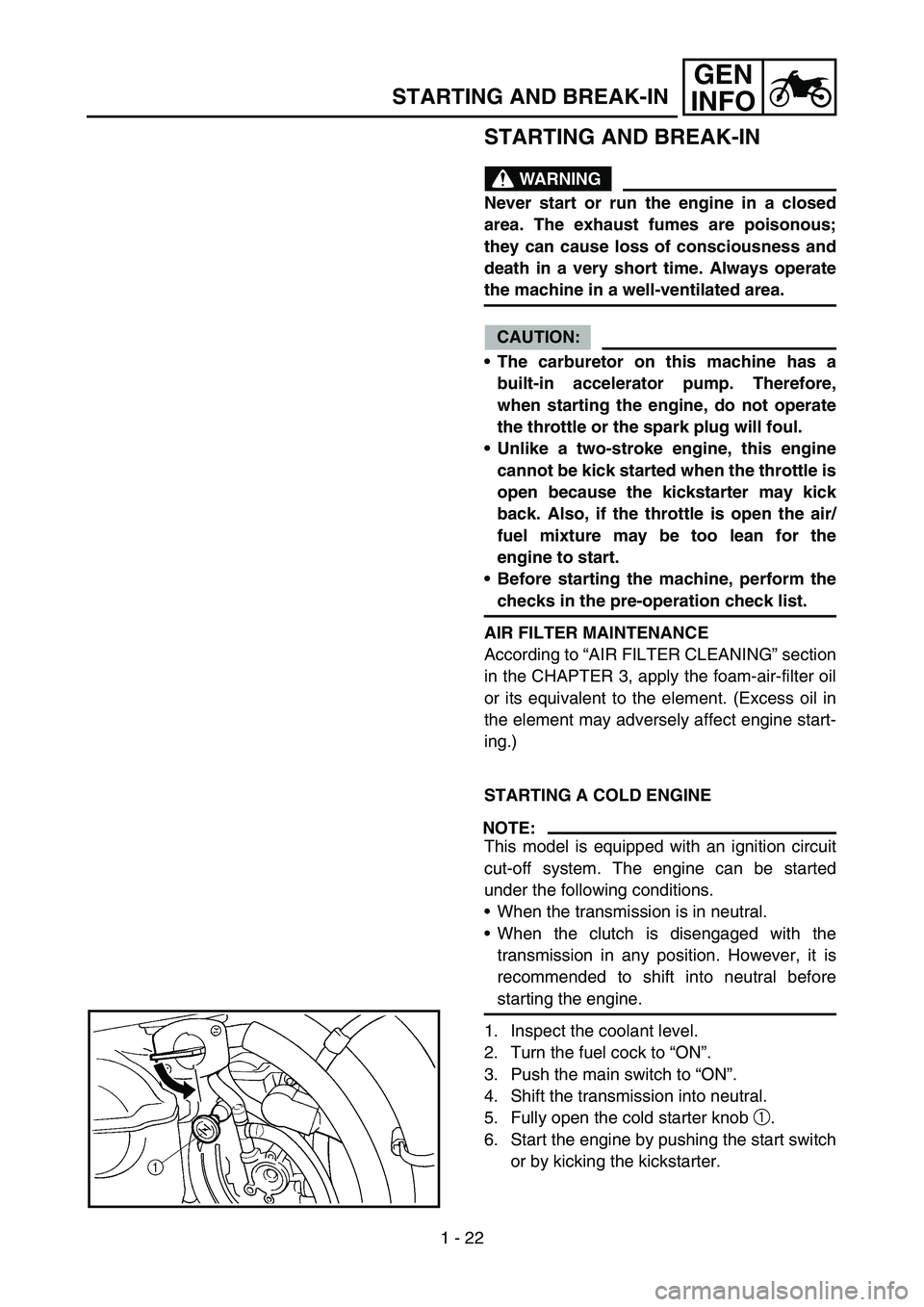
5. Fully open the cold starter knob 1.
6. Start the engine by pushing the start switch
or by kicking the kickstarter.
Page 82 of 786
GEN
INFO
1 - 26
TORQUE-CHECK POINTS
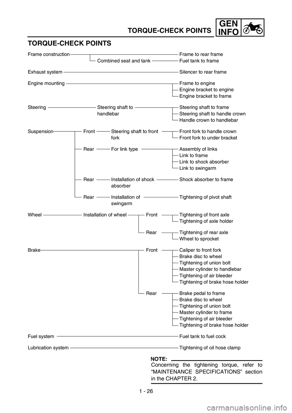
TORQUE-CHECK POINTS
NOTE:
Concerning the tightening torque, refer to
“MAINTENANCE SPECIFICATIONS” section
in the CHAPTER 2.
Frame to rear frame
Fuel tank to frame
Silencer to rear frame
Frame to engine
Engine bracket to engine
Engine bracket to frame
Steering shaft to frame
Steering shaft to handle crown
Handle crown to handlebar
Front fork to handle crown
Front fork to under bracket
Assembly of links
Link to frame
Link to shock absorber
Link to swingarm
Shock absorber to frame
Tightening of pivot shaft
Tightening of front axle
Tightening of axle holder
Tightening of rear axle
Wheel to sprocket
Caliper to front fork
Brake disc to wheel
Tightening of union bolt
Master cylinder to handlebar
Tightening of air bleeder
Tightening of brake hose holder
Brake pedal to frame
Brake disc to wheel
Tightening of union bolt
Master cylinder to frame
Tightening of air bleeder
Tightening of brake hose holder
Fuel tank to fuel cock
Tightening of oil hose clamp Frame construction
Combined seat and tank
Exhaust system
Engine mounting
Steering Steering shaft to
handlebar
Suspension Front Steering shaft to front
fork
Rear For link type
Rear Installation of shock
absorber
Rear Installation of
swingarm
Wheel Installation of wheel Front
Rear
Brake Front
Rear
Fuel system
Lubrication system
Page 99 of 786
SPEC
2 - 10 Item Standard
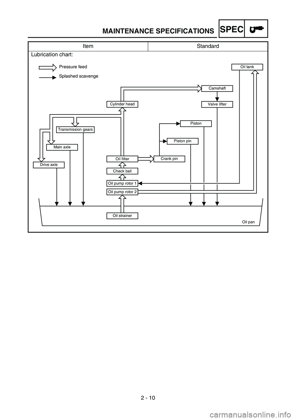
Lubrication chart:
Pressure feed
Splashed scavenge
Oil strainer
Oil pan Oil pump rotor 2
Oil pump rotor 1
Oil tank
Oil filter
Check ball
Cylinder head
Crank pinPiston pinPiston
Drive axleMain axleTransmission gears
Camshaft
Valve lifter
MAINTENANCE SPECIFICATIONS
Page 101 of 786
SPEC
2 - 12
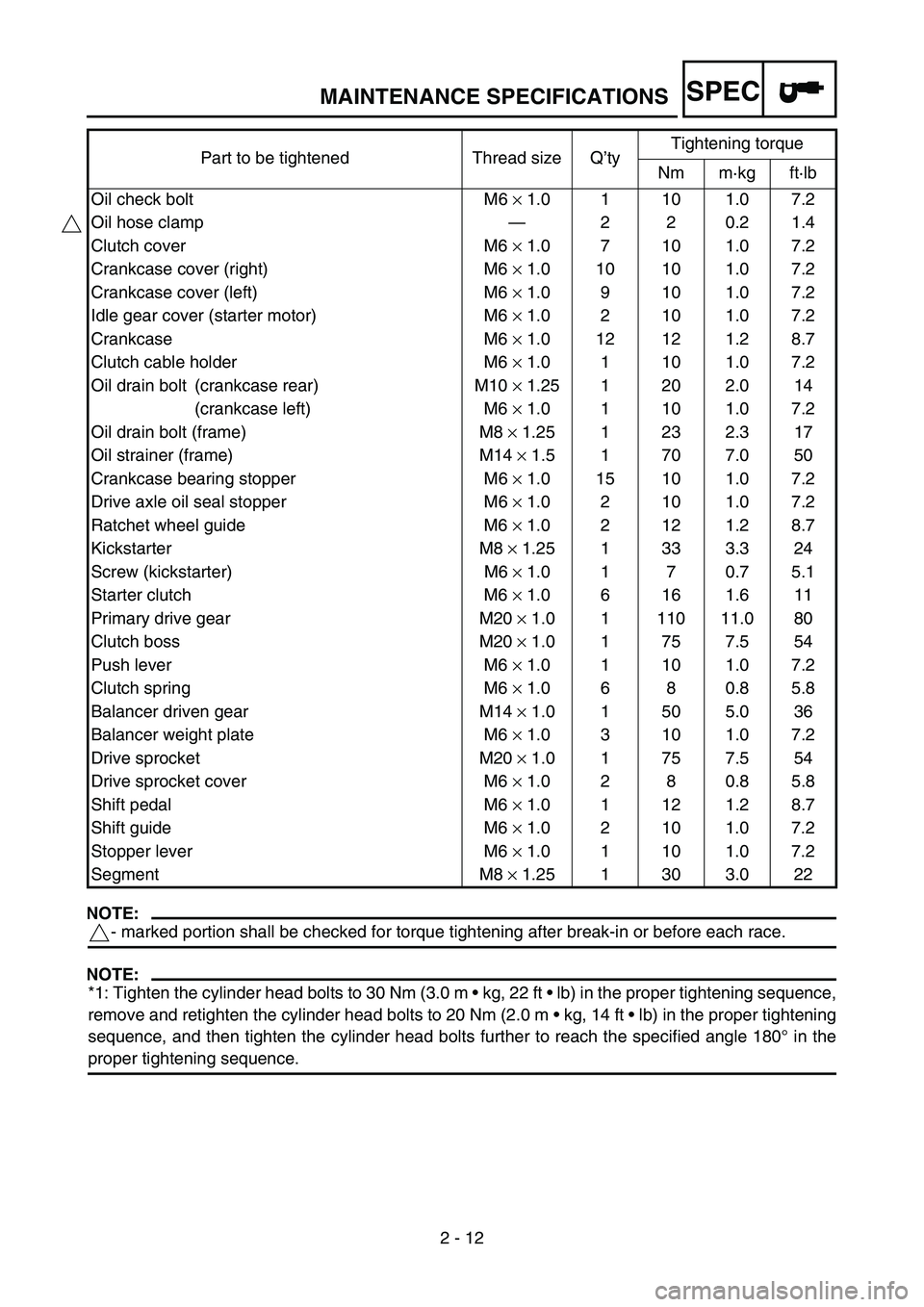
NOTE:
- marked portion shall be checked for torque tightening after break-in or before each race.
NOTE:
*1: Tighten the cylinder head bolts to 30 Nm (3.0 m kg, 22 ft lb) in the proper tightening sequence,
remove and retighten the cylinder head bolts to 20 Nm (2.0 m kg, 14 ft lb) in the proper tightening
sequence, and then tighten the cylinder head bolts further to reach the specified angle 180° in the
proper tightening sequence.Oil check bolt M6 × 1.0 1 10 1.0 7.2
Oil hose clamp—220.21.4
Clutch cover M6 × 1.0 7 10 1.0 7.2
Crankcase cover (right) M6 × 1.0 10 10 1.0 7.2
Crankcase cover (left) M6 × 1.0 9 10 1.0 7.2
Idle gear cover (starter motor) M6 × 1.0 2 10 1.0 7.2
Crankcase M6 × 1.0 12 12 1.2 8.7
Clutch cable holder M6 × 1.0 1 10 1.0 7.2
Oil drain bolt (crankcase rear) M10 × 1.25 1 20 2.0 14
(crankcase left) M6 × 1.0 1 10 1.0 7.2
Oil drain bolt (frame) M8 × 1.25 1 23 2.3 17
Oil strainer (frame) M14 × 1.5 1 70 7.0 50
Crankcase bearing stopper M6 × 1.0 15 10 1.0 7.2
Drive axle oil seal stopper M6 × 1.0 2 10 1.0 7.2
Ratchet wheel guide M6 × 1.0 2 12 1.2 8.7
Kickstarter M8 × 1.25 1 33 3.3 24
Screw (kickstarter) M6 × 1.0 1 7 0.7 5.1
Starter clutch M6 × 1.0 6 16 1.6 11
Primary drive gear M20 × 1.0 1 110 11.0 80
Clutch boss M20 × 1.0 1 75 7.5 54
Push lever M6 × 1.0 1 10 1.0 7.2
Clutch spring M6 × 1.0 6 8 0.8 5.8
Balancer driven gear M14 × 1.0 1 50 5.0 36
Balancer weight plate M6 × 1.0 3 10 1.0 7.2
Drive sprocket M20 × 1.0 1 75 7.5 54
Drive sprocket cover M6 × 1.0 2 8 0.8 5.8
Shift pedal M6 × 1.0 1 12 1.2 8.7
Shift guide M6 × 1.0 2 10 1.0 7.2
Stopper lever M6 × 1.0 1 10 1.0 7.2
Segment M8 × 1.25 1 30 3.0 22 Part to be tightened Thread size Q’tyTightening torque
Nm m·kg ft·lb
MAINTENANCE SPECIFICATIONS
Page 188 of 786
3 - 1
INSP
ADJ
MAINTENANCE INTERVALS
EC300000
REGULAR INSPECTION AND ADJUSTMENTS
MAINTENANCE INTERVALS
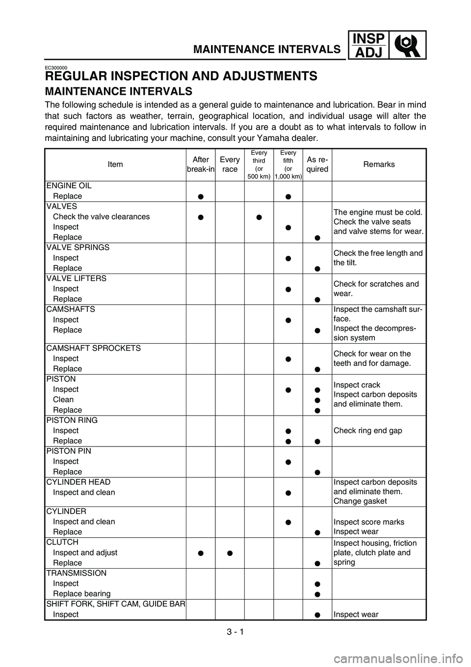
The following schedule is intended as a general guide to maintenance and lubrication. Bear in mind
that such factors as weather, terrain, geographical location, and individual usage will alter the
required maintenance and lubrication intervals. If you are a doubt as to what intervals to follow in
maintaining and lubricating your machine, consult your Yamaha dealer.
ItemAfter
break-inEvery
race
Every
third
(or
500 km)Every
fifth
(or
1,000 km)As re-
quiredRemarks
ENGINE OIL
Replace
VALVES
The engine must be cold.
Check the valve seats
and valve stems for wear. Check the valve clearances
Inspect
Replace
VALVE SPRINGS
Check the free length and
the tilt. Inspect
Replace
VALVE LIFTERS
Check for scratches and
wear. Inspect
Replace
CAMSHAFTS Inspect the camshaft sur-
face.
Inspect the decompres-
sion system Inspect
Replace
CAMSHAFT SPROCKETS
Check for wear on the
teeth and for damage. Inspect
Replace
PISTON
Inspect crack
Inspect carbon deposits
and eliminate them. Inspect
Clean
Replace
PISTON RING
Check ring end gap Inspect
Replace
PISTON PIN
Inspect
Replace
CYLINDER HEAD Inspect carbon deposits
and eliminate them.
Change gasket Inspect and clean
CYLINDER
Inspect and clean
Inspect score marks
Inspect wear
Replace
CLUTCH
Inspect housing, friction
plate, clutch plate and
spring Inspect and adjust
Replace
TRANSMISSION
Inspect
Replace bearing
SHIFT FORK, SHIFT CAM, GUIDE BAR
InspectInspect wear
Page 189 of 786
3 - 2
INSP
ADJ
MAINTENANCE INTERVALS
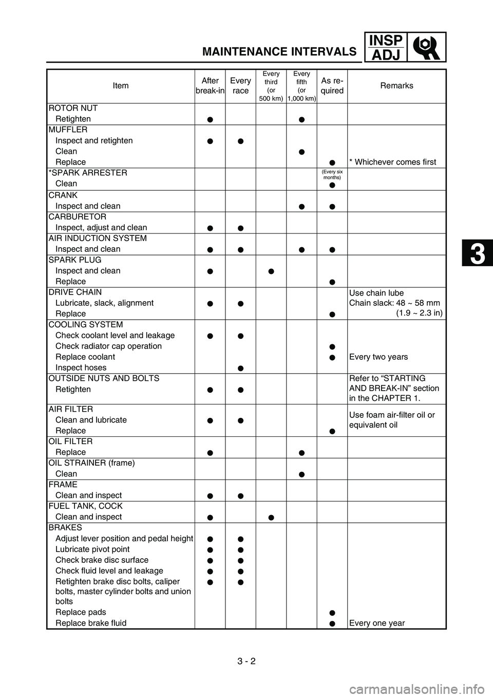
ROTOR NUT
Retighten
MUFFLER
Inspect and retighten
Clean
Replace * Whichever comes first
*SPARK ARRESTER
(Every six
months)
Clean
CRANK
Inspect and clean
CARBURETOR
Inspect, adjust and clean
AIR INDUCTION SYSTEM
Inspect and clean
SPARK PLUG
Inspect and clean
Replace
DRIVE CHAIN
Use chain lube
Chain slack: 48 ~ 58 mm
(1.9 ~ 2.3 in) Lubricate, slack, alignment
Replace
COOLING SYSTEM
Check coolant level and leakage
Check radiator cap operation
Replace coolant Every two years
Inspect hoses
OUTSIDE NUTS AND BOLTS Refer to “STARTING
AND BREAK-IN” section
in the CHAPTER 1. Retighten
AIR FILTER
Use foam air-filter oil or
equivalent oil Clean and lubricate
Replace
OIL FILTER
Replace
OIL STRAINER (frame)
Clean
FRAME
Clean and inspect
FUEL TANK, COCK
Clean and inspect
BRAKES
Adjust lever position and pedal height
Lubricate pivot point
Check brake disc surface
Check fluid level and leakage
Retighten brake disc bolts, caliper
bolts, master cylinder bolts and union
bolts
Replace pads
Replace brake fluid Every one yearItemAfter
break-inEvery
race
Every
third
(or
500 km)Every
fifth
(or
1,000 km)As re-
quiredRemarks
3
Page 190 of 786
3 - 3
INSP
ADJ
MAINTENANCE INTERVALS
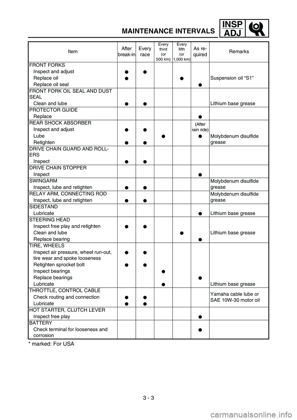
* marked: For USA
FRONT FORKS
Inspect and adjust
Replace oil Suspension oil “S1”
Replace oil seal
FRONT FORK OIL SEAL AND DUST
SEAL
Clean and lube Lithium base grease
PROTECTOR GUIDE
Replace
REAR SHOCK ABSORBER
(After
rain ride)
Inspect and adjust
Lube
Molybdenum disulfide
grease
Retighten
DRIVE CHAIN GUARD AND ROLL-
ERS
Inspect
DRIVE CHAIN STOPPER
Inspect
SWINGARM
Molybdenum disulfide
grease
Inspect, lube and retighten
RELAY ARM, CONNECTING ROD
Molybdenum disulfide
grease
Inspect, lube and retighten
SIDESTAND
Lubricate Lithium base grease
STEERING HEAD
Inspect free play and retighten
Clean and lube Lithium base grease
Replace bearing
TIRE, WHEELS
Inspect air pressure, wheel run-out,
tire wear and spoke looseness
Retighten sprocket bolt
Inspect bearings
Replace bearings
Lubricate Lithium base grease
THROTTLE, CONTROL CABLE
Yamaha cable lube or
SAE 10W-30 motor oil Check routing and connection
Lubricate
HOT STARTER, CLUTCH LEVER
Inspect free play
BATTERY
Check terminal for looseness and
corrosionItemAfter
break-inEvery
race
Every
third
(or
500 km)Every
fifth
(or
1,000 km)As re-
quiredRemarks
Page 200 of 786
3 - 4
INSP
ADJ
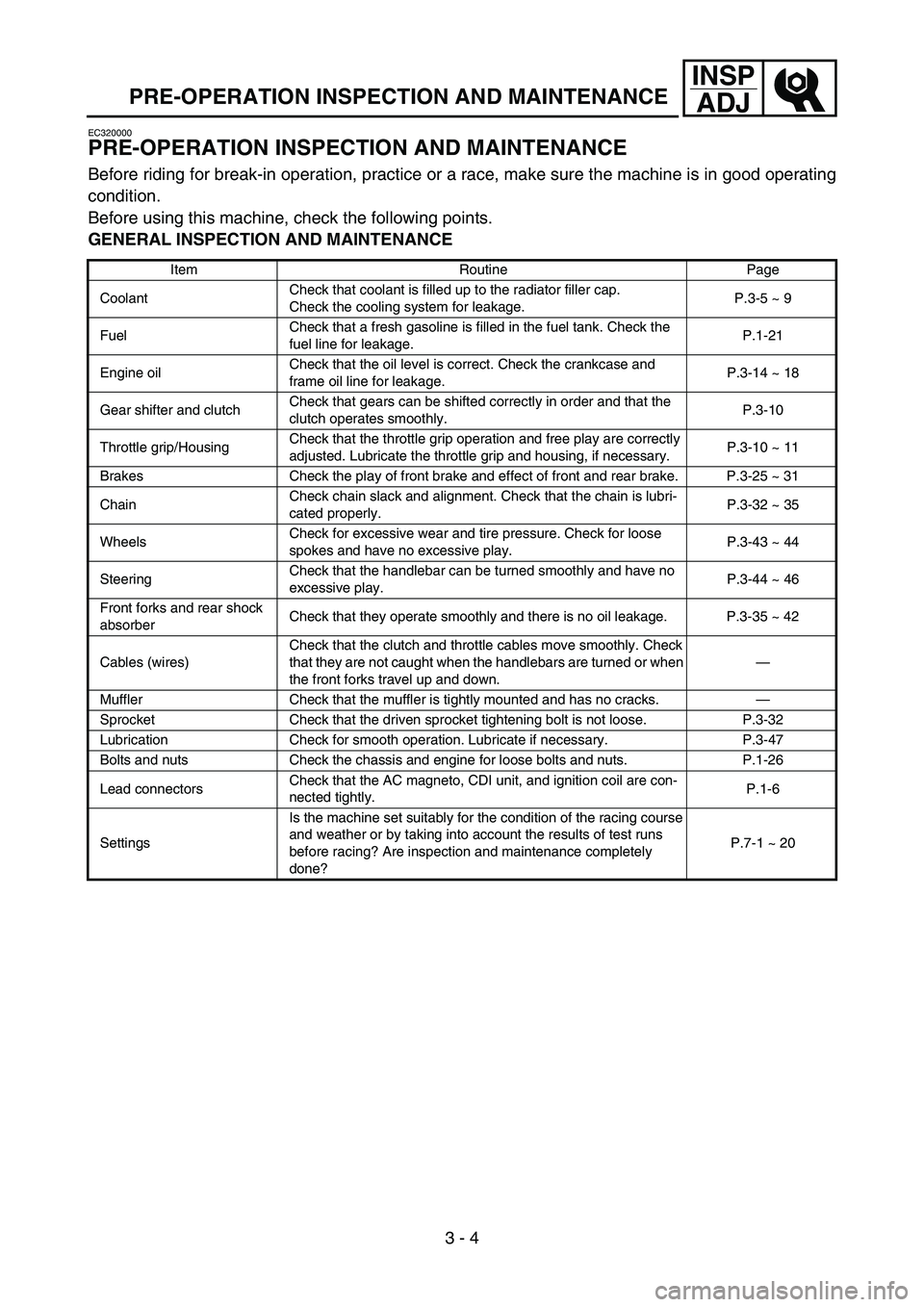
PRE-OPERATION INSPECTION AND MAINTENANCE
EC320000
PRE-OPERATION INSPECTION AND MAINTENANCE
Before riding for break-in operation, practice or a race, make sure the machine is in good operating
condition.
Before using this machine, check the following points.
GENERAL INSPECTION AND MAINTENANCE
Item Routine Page
CoolantCheck that coolant is filled up to the radiator filler cap.
Check the cooling system for leakage.P.3-5 ~ 9
FuelCheck that a fresh gasoline is filled in the fuel tank. Check the
fuel line for leakage.P.1-21
Engine oilCheck that the oil level is correct. Check the crankcase and
frame oil line for leakage.P.3-14 ~ 18
Gear shifter and clutchCheck that gears can be shifted correctly in order and that the
clutch operates smoothly.P.3-10
Throttle grip/HousingCheck that the throttle grip operation and free play are correctly
adjusted. Lubricate the throttle grip and housing, if necessary.P.3-10 ~ 11
Brakes Check the play of front brake and effect of front and rear brake. P.3-25 ~ 31
ChainCheck chain slack and alignment. Check that the chain is lubri-
cated properly.P.3-32 ~ 35
WheelsCheck for excessive wear and tire pressure. Check for loose
spokes and have no excessive play.P.3-43 ~ 44
SteeringCheck that the handlebar can be turned smoothly and have no
excessive play.P.3-44 ~ 46
Front forks and rear shock
absorberCheck that they operate smoothly and there is no oil leakage. P.3-35 ~ 42
Cables (wires)Check that the clutch and throttle cables move smoothly. Check
that they are not caught when the handlebars are turned or when
the front forks travel up and down.—
Muffler Check that the muffler is tightly mounted and has no cracks.—
Sprocket Check that the driven sprocket tightening bolt is not loose. P.3-32
Lubrication Check for smooth operation. Lubricate if necessary. P.3-47
Bolts and nuts Check the chassis and engine for loose bolts and nuts. P.1-26
Lead connectorsCheck that the AC magneto, CDI unit, and ignition coil are con-
nected tightly.P.1-6
SettingsIs the machine set suitably for the condition of the racing course
and weather or by taking into account the results of test runs
before racing? Are inspection and maintenance completely
done?P.7-1 ~ 20
Page 222 of 786

3 - 14
INSP
ADJ
ENGINE OIL LEVEL INSPECTION
ENGINE OIL LEVEL INSPECTION
1. Stand the machine on a level surface.
NOTE:
When checking the oil level make sure that
the machine is upright.
Place the machine on a suitable stand.
WARNING
Never remove the oil tank cap just after
high speed operation. The heated oil could
spurt out. causing danger. Wait until the oil
cools down to approximately 70 °C (158 °F).
2. Idle the engine more than 3 minutes while
keeping the machine upright. Then stop the
engine and inspect the oil level.
3. Remove:
Oil tank cap 1
1
4. Inspect:
Oil level
Oil level should be between maximum a
and minimum b marks.
Oil level low → Add oil to proper level.
NOTE:
When inspecting the oil level, do not screw the
oil level gauge into the oil tank.
Insert the gauge lightly.
a
b