YAMAHA WR 450F 2009 Owner's Guide
Manufacturer: YAMAHA, Model Year: 2009, Model line: WR 450F, Model: YAMAHA WR 450F 2009Pages: 226, PDF Size: 14.26 MB
Page 31 of 226
2-4
MAINTENANCE SPECIFICATIONS
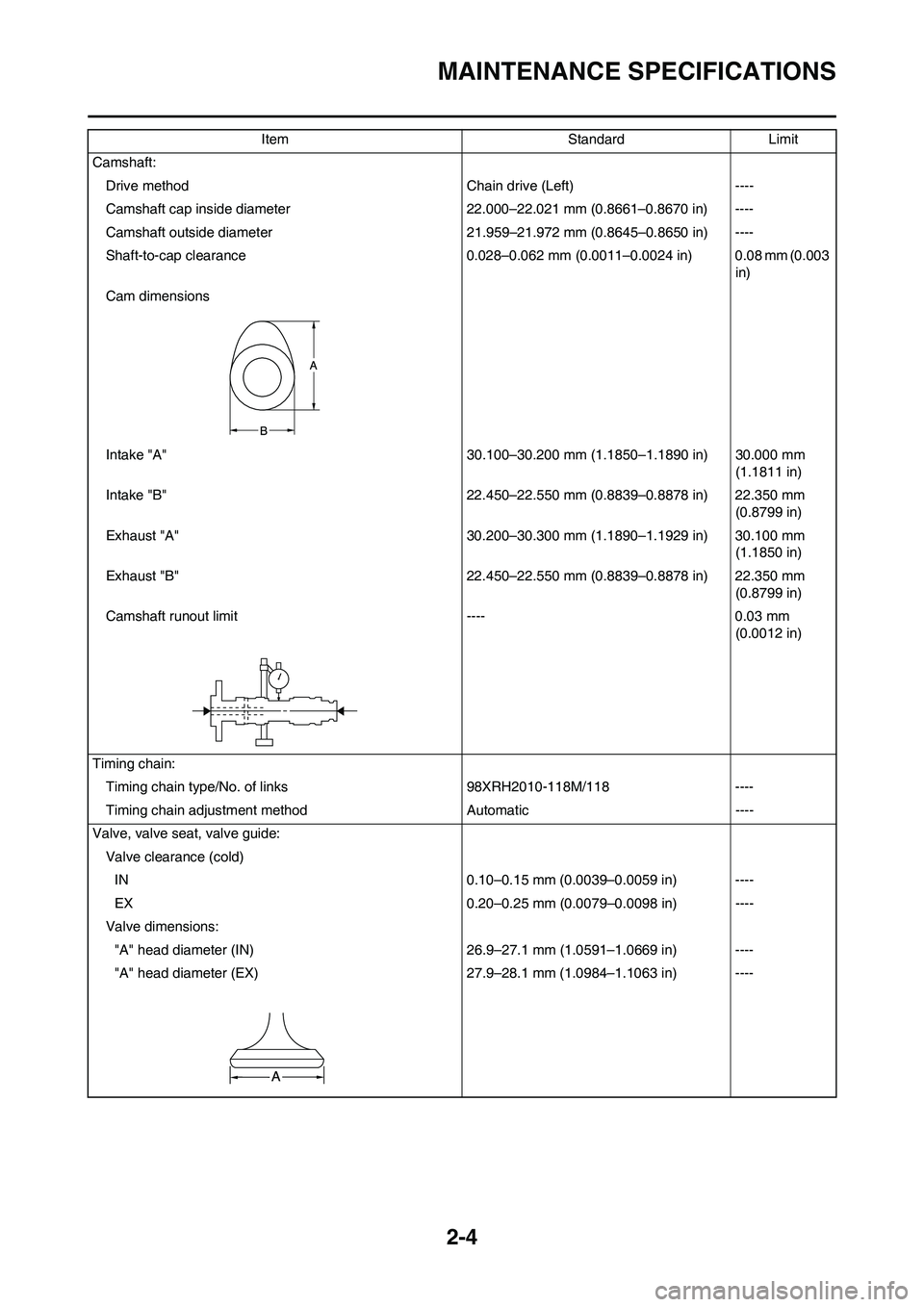
Camshaft:
Drive method Chain drive (Left) ----
Camshaft cap inside diameter 22.000–22.021 mm (0.8661–0.8670 in) ----
Camshaft outside diameter 21.959–21.972 mm (0.8645–0.8650 in) ----
Shaft-to-cap clearance 0.028–0.062 mm (0.0011–0.0024 in) 0.08 mm (0.003
in)
Cam dimensions
Intake "A" 30.100–30.200 mm (1.1850–1.1890 in) 30.000 mm
(1.1811 in)
Intake "B" 22.450–22.550 mm (0.8839–0.8878 in) 22.350 mm
(0.8799 in)
Exhaust "A" 30.200–30.300 mm (1.1890–1.1929 in) 30.100 mm
(1.1850 in)
Exhaust "B" 22.450–22.550 mm (0.8839–0.8878 in) 22.350 mm
(0.8799 in)
Camshaft runout limit ---- 0.03 mm
(0.0012 in)
Timing chain:
Timing chain type/No. of links 98XRH2010-118M/118 ----
Timing chain adjustment method Automatic ----
Valve, valve seat, valve guide:
Valve clearance (cold)
IN 0.10–0.15 mm (0.0039–0.0059 in) ----
EX 0.20–0.25 mm (0.0079–0.0098 in) ----
Valve dimensions:
"A" head diameter (IN) 26.9–27.1 mm (1.0591–1.0669 in) ----
"A" head diameter (EX) 27.9–28.1 mm (1.0984–1.1063 in) ----Item Standard Limit
Page 32 of 226
2-5
MAINTENANCE SPECIFICATIONS
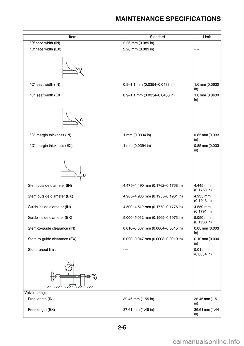
"B" face width (IN) 2.26 mm (0.089 in) ----
"B" face width (EX) 2.26 mm (0.089 in) ----
"C" seat width (IN) 0.9–1.1 mm (0.0354–0.0433 in) 1.6 mm (0.0630
in)
"C" seat width (EX) 0.9–1.1 mm (0.0354–0.0433 in) 1.6 mm (0.0630
in)
"D" margin thickness (IN) 1 mm (0.0394 in) 0.85 mm (0.033
in)
"D" margin thickness (EX) 1 mm (0.0394 in) 0.85 mm (0.033
in)
Stem outside diameter (IN) 4.475–4.490 mm (0.1762–0.1768 in) 4.445 mm
(0.1750 in)
Stem outside diameter (EX) 4.965–4.980 mm (0.1955–0.1961 in) 4.935 mm
(0.1943 in)
Guide inside diameter (IN) 4.500–4.512 mm (0.1772–0.1776 in) 4.550 mm
(0.1791 in)
Guide inside diameter (EX) 5.000–5.012 mm (0.1969–0.1973 in) 5.050 mm
(0.1988 in)
Stem-to-guide clearance (IN) 0.010–0.037 mm (0.0004–0.0015 in) 0.08 mm (0.003
in)
Stem-to-guide clearance (EX) 0.020–0.047 mm (0.0008–0.0019 in) 0.10 mm (0.004
in)
Stem runout limit ---- 0.01 mm
(0.0004 in)
Valve spring:
Free length (IN) 39.46 mm (1.55 in) 38.46 mm (1.51
in)
Free length (EX) 37.61 mm (1.48 in) 36.61 mm (1.44
in) Item Standard Limit
Page 33 of 226
2-6
MAINTENANCE SPECIFICATIONS
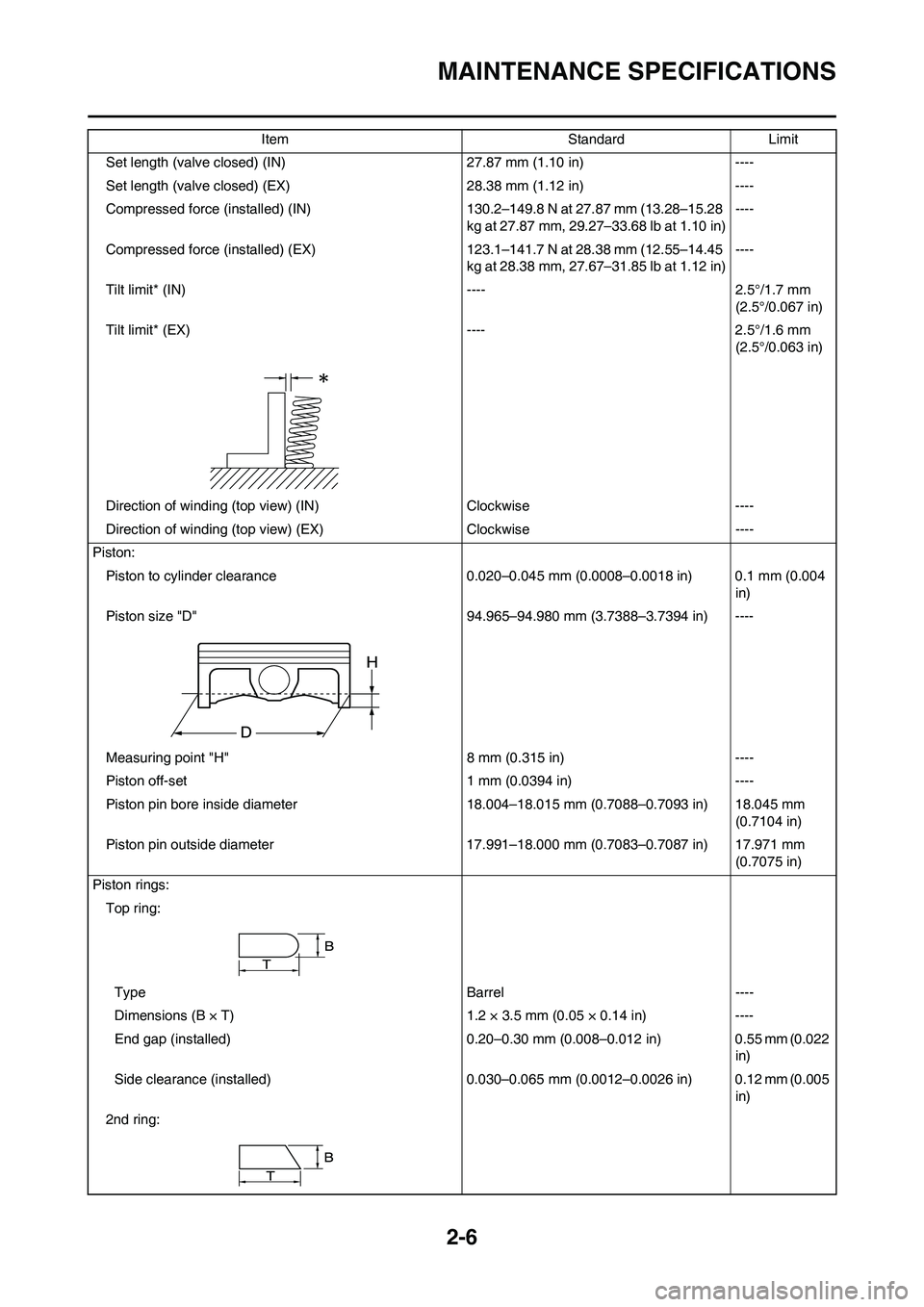
Set length (valve closed) (IN) 27.87 mm (1.10 in) ----
Set length (valve closed) (EX) 28.38 mm (1.12 in) ----
Compressed force (installed) (IN) 130.2–149.8 N at 27.87 mm (13.28–15.28
kg at 27.87 mm, 29.27–33.68 lb at 1.10 in)----
Compressed force (installed) (EX) 123.1–141.7 N at 28.38 mm (12.55–14.45
kg at 28.38 mm, 27.67–31.85 lb at 1.12 in)----
Tilt limit* (IN) ---- 2.5°/1.7 mm
(2.5°/0.067 in)
Tilt limit* (EX) ---- 2.5°/1.6 mm
(2.5°/0.063 in)
Direction of winding (top view) (IN) Clockwise ----
Direction of winding (top view) (EX) Clockwise ----
Piston:
Piston to cylinder clearance 0.020–0.045 mm (0.0008–0.0018 in) 0.1 mm (0.004
in)
Piston size "D" 94.965–94.980 mm (3.7388–3.7394 in) ----
Measuring point "H" 8 mm (0.315 in) ----
Piston off-set 1 mm (0.0394 in) ----
Piston pin bore inside diameter 18.004–18.015 mm (0.7088–0.7093 in) 18.045 mm
(0.7104 in)
Piston pin outside diameter 17.991–18.000 mm (0.7083–0.7087 in) 17.971 mm
(0.7075 in)
Piston rings:
Top ring:
Type Barrel ----
Dimensions (B × T) 1.2 × 3.5 mm (0.05 × 0.14 in) ----
End gap (installed) 0.20–0.30 mm (0.008–0.012 in) 0.55 mm (0.022
in)
Side clearance (installed) 0.030–0.065 mm (0.0012–0.0026 in) 0.12 mm (0.005
in)
2nd ring:Item Standard Limit
Page 34 of 226
2-7
MAINTENANCE SPECIFICATIONS
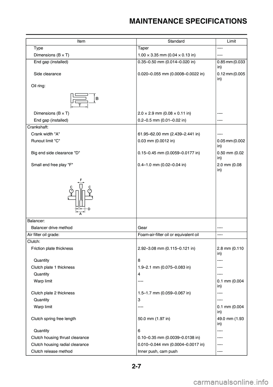
Type Taper ----
Dimensions (B × T) 1.00 × 3.35 mm (0.04 × 0.13 in) ----
End gap (installed) 0.35–0.50 mm (0.014–0.020 in) 0.85 mm (0.033
in)
Side clearance 0.020–0.055 mm (0.0008–0.0022 in) 0.12 mm (0.005
in)
Oil ring:
Dimensions (B × T) 2.0 × 2.9 mm (0.08 × 0.11 in) ----
End gap (installed) 0.2–0.5 mm (0.01–0.02 in) ----
Crankshaft:
Crank width "A" 61.95–62.00 mm (2.439–2.441 in) ----
Runout limit "C" 0.03 mm (0.0012 in) 0.05 mm (0.002
in)
Big end side clearance "D" 0.15–0.45 mm (0.0059–0.0177 in) 0.50 mm (0.02
in)
Small end free play "F" 0.4–1.0 mm (0.02–0.04 in) 2.0 mm (0.08
in)
Balancer:
Balancer drive method Gear ----
Air filter oil grade: Foam-air-filter oil or equivalent oil ----
Clutch:
Friction plate thickness 2.92–3.08 mm (0.115–0.121 in) 2.8 mm (0.110
in)
Quantity 8 ----
Clutch plate 1 thickness 1.9–2.1 mm (0.075–0.083 in) ----
Quantity 4 ----
Warp limit ---- 0.1 mm (0.004
in)
Clutch plate 2 thickness 1.5–1.7 mm (0.059–0.067 in) ----
Quantity 3 ----
Warp limit ---- 0.1 mm (0.004
in)
Clutch spring free length 50.0 mm (1.97 in) 49.0 mm (1.93
in)
Quantity 6 ----
Clutch housing thrust clearance 0.10–0.35 mm (0.0039–0.0138 in) ----
Clutch housing radial clearance 0.010–0.044 mm (0.0004–0.0017 in) ----
Clutch release method Inner push, cam push ----Item Standard Limit
Page 35 of 226
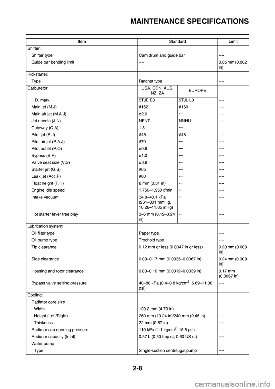
2-8
MAINTENANCE SPECIFICATIONS
Shifter:
Shifter type Cam drum and guide bar ----
Guide bar bending limit ---- 0.05 mm (0.002
in)
Kickstarter:
Type Ratchet type ----
Carburetor: USA, CDN, AUS,
NZ, ZAEUROPE
I. D. mark 5TJE E0 5TJL L0 ----
Main jet (M.J) #162 #160 ----
Main air jet (M.A.J) ø2.0←----
Jet needle (J.N) NFNT NNHU ----
Cutaway (C.A) 1.5←----
Pilot jet (P.J) #45 #48 ----
Pilot air jet (P.A.J) #70←----
Pilot outlet (P.O) ø0.9←----
Bypass (B.P) ø1.0←----
Valve seat size (V.S) ø3.8←----
Starter jet (G.S) #65←----
Leak jet (Acc.P) #60←----
Float height (F.H) 8 mm (0.31 in)←----
Engine idle speed 1,750–1,950 r/min←----
Intake vacuum 34.8–40.1 kPa
(261–301 mmHg,
10.28–11.85 inHg)←----
Hot starter lever free play 3–6 mm (0.12–0.24
in)←----
Lubrication system:
Oil filter type Paper type ----
Oil pump type Trochoid type ----
Tip clearance 0.12 mm or less (0.0047 in or less) 0.20 mm (0.008
in)
Side clearance 0.09–0.17 mm (0.0035–0.0067 in) 0.24 mm (0.009
in)
Housing and rotor clearance 0.03–0.10 mm (0.0012–0.0039 in) 0.17 mm
(0.0067 in)
Bypass valve setting pressure 40–80 kPa (0.4–0.8 kg/cm
2, 5.69–11.38
psi)----
Cooling:
Radiator core size
Width 120.2 mm (4.73 in) ----
Height (Left/Right) 260 mm (10.24 in)/240 mm (9.45 in) ----
Thickness 22 mm (0.87 in) ----
Radiator cap opening pressure 110 kPa (1.1 kg/cm
2, 15.6 psi) ----
Radiator capacity (total) 0.57 L (0.50 Imp qt, 0.60 US qt) ----
Water pump
Type Single-suction centrifugal pump ----Item Standard Limit
Page 36 of 226
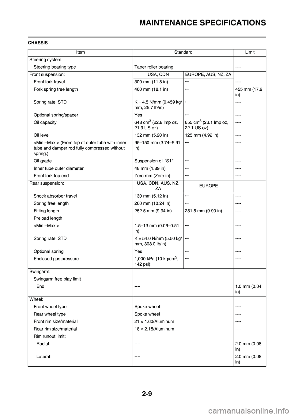
2-9
MAINTENANCE SPECIFICATIONS
CHASSIS
Item Standard Limit
Steering system:
Steering bearing typeTaper roller bearing ----
Front suspension: USA, CDN EUROPE, AUS, NZ, ZA
Front fork travel 300 mm (11.8 in)←----
Fork spring free length 460 mm (18.1 in)←455 mm (17.9
in)
Spring rate, STD K = 4.5 N/mm (0.459 kg/
mm, 25.7 lb/in)←----
Optional spring/spacer Yes←----
Oil capacity 648 cm
3 (22.8 lmp oz,
21.9 US oz)655 cm3 (23.1 lmp oz,
22.1 US oz)----
Oil level 132 mm (5.20 in) 125 mm (4.92 in) ----
tube and damper rod fully compressed without
spring.)95–150 mm (3.74–5.91
in)←----
Oil grade Suspension oil "S1"←----
Inner tube outer diameter 48 mm (1.89 in)←----
Front fork top end Zero mm (Zero in)←----
Rear suspension: USA, CDN, AUS, NZ,
ZAEUROPE
Shock absorber travel 130 mm (5.12 in)←----
Spring free length 260 mm (10.24 in)←----
Fitting length 252.5 mm (9.94 in) 251.5 mm (9.90 in) ----
Preload length
in)←----
Spring rate, STD K = 54.0 N/mm (5.50 kg/
mm, 308.0 lb/in)←----
Optional spring Yes←----
Enclosed gas pressure 1,000 kPa (10 kg/cm
2,
142 psi)←----
Swingarm:
Swingarm free play limit
End ---- 1.0 mm (0.04
in)
Wheel:
Front wheel type Spoke wheel ----
Rear wheel typeSpoke wheel ----
Front rim size/material 21 × 1.60/Aluminum ----
Rear rim size/material 18 × 2.15/Aluminum ----
Rim runout limit:
Radial ---- 2.0 mm (0.08
in)
Lateral ---- 2.0 mm (0.08
in)
Page 37 of 226
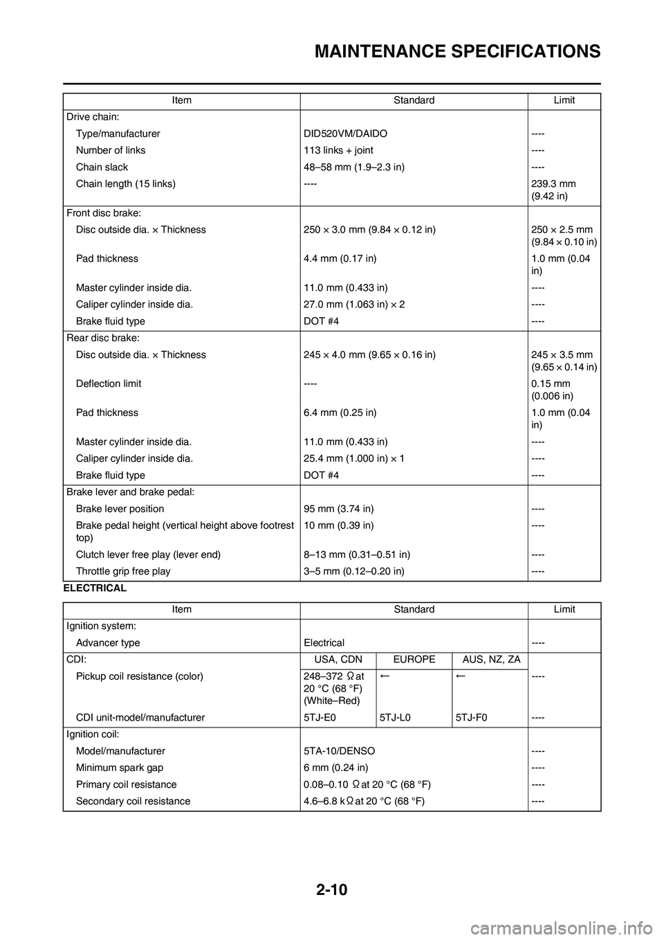
2-10
MAINTENANCE SPECIFICATIONS
ELECTRICALDrive chain:
Type/manufacturer DID520VM/DAIDO ----
Number of links 113 links + joint ----
Chain slack 48–58 mm (1.9–2.3 in) ----
Chain length (15 links) ---- 239.3 mm
(9.42 in)
Front disc brake:
Disc outside dia. × Thickness 250 × 3.0 mm (9.84 × 0.12 in) 250 × 2.5 mm
(9.84 × 0.10 in)
Pad thickness 4.4 mm (0.17 in) 1.0 mm (0.04
in)
Master cylinder inside dia. 11.0 mm (0.433 in) ----
Caliper cylinder inside dia. 27.0 mm (1.063 in) × 2 ----
Brake fluid type DOT #4 ----
Rear disc brake:
Disc outside dia. × Thickness 245 × 4.0 mm (9.65 × 0.16 in) 245 × 3.5 mm
(9.65 × 0.14 in)
Deflection limit ---- 0.15 mm
(0.006 in)
Pad thickness 6.4 mm (0.25 in) 1.0 mm (0.04
in)
Master cylinder inside dia. 11.0 mm (0.433 in) ----
Caliper cylinder inside dia. 25.4 mm (1.000 in) × 1 ----
Brake fluid type DOT #4 ----
Brake lever and brake pedal:
Brake lever position 95 mm (3.74 in) ----
Brake pedal height (vertical height above footrest
top)10 mm (0.39 in) ----
Clutch lever free play (lever end) 8–13 mm (0.31–0.51 in) ----
Throttle grip free play3–5 mm (0.12–0.20 in) ---- Item Standard Limit
Item Standard Limit
Ignition system:
Advancer type Electrical ----
CDI: USA, CDN EUROPE AUS, NZ, ZA
Pickup coil resistance (color) 248–372 Ωat
20 °C (68 °F)
(White–Red)←←----
CDI unit-model/manufacturer 5TJ-E0 5TJ-L0 5TJ-F0 ----
Ignition coil:
Model/manufacturer 5TA-10/DENSO ----
Minimum spark gap 6 mm (0.24 in) ----
Primary coil resistance 0.08–0.10 Ωat 20 °C (68 °F) ----
Secondary coil resistance 4.6–6.8 kΩat 20 °C (68 °F) ----
Page 38 of 226
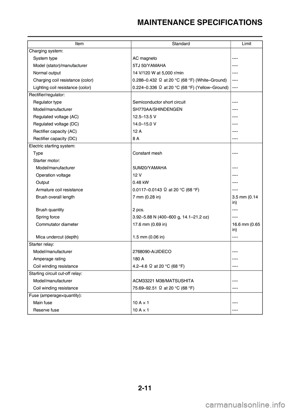
2-11
MAINTENANCE SPECIFICATIONS
Charging system:
System type AC magneto ----
Model (stator)/manufacturer 5TJ 50/YAMAHA ----
Normal output 14 V/120 W at 5,000 r/min ----
Charging coil resistance (color) 0.288–0.432 Ω at 20 °C (68 °F) (White–Ground) ----
Lighting coil resistance (color) 0.224–0.336 Ω at 20 °C (68 °F) (Yellow–Ground) ----
Rectifier/regulator:
Regulator type Semiconductor short circuit ----
Model/manufacturer SH770AA/SHINDENGEN ----
Regulated voltage (AC) 12.5–13.5 V ----
Regulated voltage (DC) 14.0–15.0 V ----
Rectifier capacity (AC) 12 A ----
Rectifier capacity (DC) 8 A ----
Electric starting system:
Type Constant mesh ----
Starter motor:
Model/manufacturer 5UM20/YAMAHA ----
Operation voltage 12 V ----
Output 0.48 kW ----
Armature coil resistance 0.0117–0.0143 Ω at 20 °C (68 °F) ----
Brush overall length 7 mm (0.28 in) 3.5 mm (0.14
in)
Brush quantity 2 pcs. ----
Spring force 3.92–5.88 N (400–600 g, 14.1–21.2 oz) ----
Commutator diameter 17.6 mm (0.69 in) 16.6 mm (0.65
in)
Mica undercut (depth) 1.5 mm (0.06 in) ----
Starter relay:
Model/manufacturer 2768090-A/JIDECO ----
Amperage rating 180 A ----
Coil winding resistance 4.2–4.6 Ω at 20 °C (68 °F) ----
Starting circuit cut-off relay:
Model/manufacturer ACM33221 M38/MATSUSHITA ----
Coil winding resistance 75.69–92.51 Ω at 20 °C (68 °F) ----
Fuse (amperage×quantity):
Main fuse 10 A × 1 ----
Reserve fuse 10 A × 1 ----Item Standard Limit
Page 39 of 226
2-12
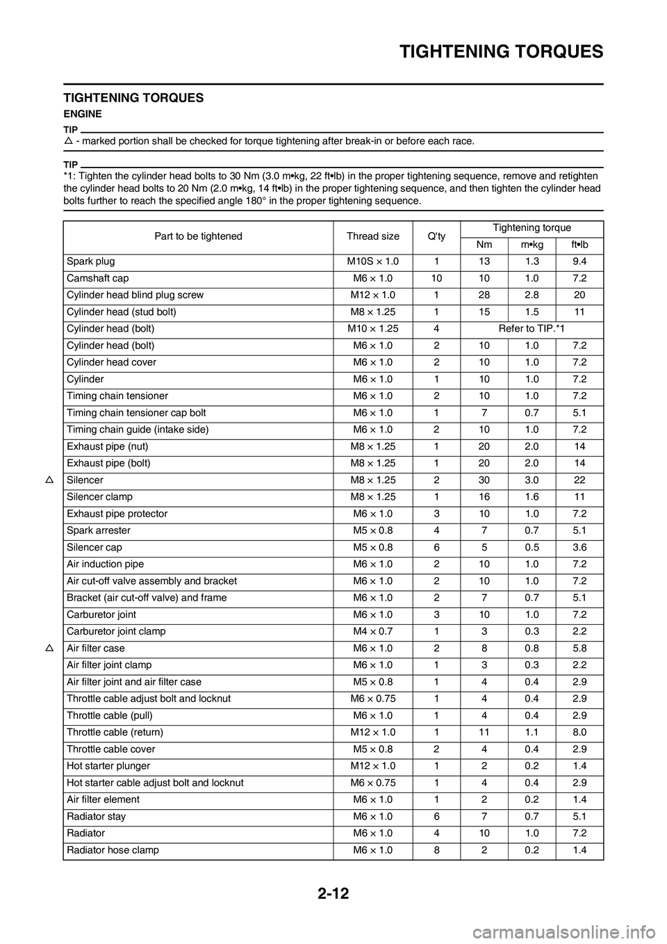
TIGHTENING TORQUES
TIGHTENING TORQUES
ENGINE
△- marked portion shall be checked for torque tightening after break-in or before each race.
*1: Tighten the cylinder head bolts to 30 Nm (3.0 m•kg, 22 ft•lb) in the proper tightening sequence, remove and retighten
the cylinder head bolts to 20 Nm (2.0 m•kg, 14 ft•lb) in the proper tightening sequence, and then tighten the cylinder head
bolts further to reach the specified angle 180° in the proper tightening sequence.
Part to be tightened Thread size Q'tyTightening torque
Nm m•kg ft•lb
Spark plug M10S × 1.0 1 13 1.3 9.4
Camshaft cap M6 × 1.0 10 10 1.0 7.2
Cylinder head blind plug screw M12 × 1.0 1 28 2.8 20
Cylinder head (stud bolt) M8 × 1.25 1 15 1.5 11
Cylinder head (bolt) M10 × 1.25 4 Refer to TIP.*1
Cylinder head (bolt) M6 × 1.0 2 10 1.0 7.2
Cylinder head cover M6 × 1.0 2 10 1.0 7.2
Cylinder M6 × 1.0 1 10 1.0 7.2
Timing chain tensioner M6 × 1.0 2 10 1.0 7.2
Timing chain tensioner cap bolt M6 × 1.0 1 7 0.7 5.1
Timing chain guide (intake side) M6 × 1.0 2 10 1.0 7.2
Exhaust pipe (nut) M8 × 1.25 1 20 2.0 14
Exhaust pipe (bolt) M8 × 1.25 1 20 2.0 14
△Silencer M8 × 1.25 2 30 3.0 22
Silencer clamp M8 × 1.25 1 16 1.6 11
Exhaust pipe protector M6 × 1.0 3 10 1.0 7.2
Spark arrester M5 × 0.8 4 7 0.7 5.1
Silencer cap M5 × 0.8 6 5 0.5 3.6
Air induction pipe M6 × 1.0 2 10 1.0 7.2
Air cut-off valve assembly and bracket M6 × 1.0 2 10 1.0 7.2
Bracket (air cut-off valve) and frame M6 × 1.0 2 7 0.7 5.1
Carburetor joint M6 × 1.0 3 10 1.0 7.2
Carburetor joint clamp M4 × 0.7 1 3 0.3 2.2
△Air filter case M6 × 1.0 2 8 0.8 5.8
Air filter joint clamp M6 × 1.0 1 3 0.3 2.2
Air filter joint and air filter case M5 × 0.8 1 4 0.4 2.9
Throttle cable adjust bolt and locknut M6 × 0.75 1 4 0.4 2.9
Throttle cable (pull) M6 × 1.0 1 4 0.4 2.9
Throttle cable (return) M12 × 1.0 1 11 1.1 8.0
Throttle cable cover M5 × 0.8 2 4 0.4 2.9
Hot starter plunger M12 × 1.0 1 2 0.2 1.4
Hot starter cable adjust bolt and locknut M6 × 0.75 1 4 0.4 2.9
Air filter element M6 × 1.0 1 2 0.2 1.4
Radiator stay M6 × 1.0 6 7 0.7 5.1
Radiator M6 × 1.0 4 10 1.0 7.2
Radiator hose clamp M6 × 1.0 8 2 0.2 1.4
Page 40 of 226

2-13
TIGHTENING TORQUES
Radiator pipe 1, 2 M10 × 1.0 2 10 1.0 7.2
Impeller M8 × 1.25 1 14 1.4 10
Water pump housing cover M6 × 1.0 3 10 1.0 7.2
Coolant drain bolt M6 × 1.0 1 10 1.0 7.2
Oil pump cover M4 × 0.7 1 2 0.2 1.4
Oil pump M6 × 1.0 2 10 1.0 7.2
Oil pump drive gear shaft M6 × 1.0 1 10 1.0 7.2
Engine oil drain bolt (oil filter) M6 × 1.0 1 10 1.0 7.2
Oil filter cover M6 × 1.0 2 10 1.0 7.2
Oil check bolt (cylinder head) M6 × 1.0 1 10 1.0 7.2
△Oil hose clamp — 2 2 0.2 1.4
Crankshaft end accessing screw M27 × 1.5 1 10 1.0 7.2
Timing mark accessing screw M14 × 1.5 1 6 0.6 4.3
Clutch cover M6 × 1.0 7 10 1.0 7.2
Crankcase cover (right) M6 × 1.0 8 10 1.0 7.2
Crankcase cover (right) M6 × 1.0 2 12 1.2 8.7
Crankcase cover (left) M6 × 1.0 8 10 1.0 7.2
Idle gear cover (starter motor) M6 × 1.0 2 10 1.0 7.2
Crankcase M6 × 1.0 12 12 1.2 8.7
Clutch cable holder M6 × 1.0 1 10 1.0 7.2
Oil drain bolt (crankcase right) M6 × 1.25 1 20 2.0 14
Oil drain bolt (crankcase left) M6 × 1.0 1 20 2.0 14
Oil check bolt (crankcase) M6 × 1.0 1 10 1.0 7.2
Oil strainer M6 × 1.0 1 10 1.0 7.2
Crankcase bearing stopper M6 × 1.0 4 14 1.4 10
Crankcase bearing stopper M6 × 1.0 8 10 1.0 7.2
Drive axle oil seal stopper M6 × 1.0 2 10 1.0 7.2
Ratchet wheel guide M6 × 1.0 2 12 1.2 8.7
Kickstarter crank M8 × 1.25 1 33 3.3 24
Screw (kickstarter crank) M6 × 1.0 1 7 0.7 5.1
Starter clutch M6 × 1.0 6 16 1.6 11
Primary drive gear M20 × 1.0 1 110 11.0 80
Clutch boss M20 × 1.0 1 75 7.5 54
Clutch cable adjust bolt and locknut M8 × 1.0 1 4 0.4 2.9
Clutch spring M6 × 1.0 6 10 1.0 7.2
Balancer M10 × 1.0 1 45 4.5 32
Balancer driven gear M14 × 1.0 1 50 5.0 36
Balancer weight plate M6 × 1.0 3 10 1.0 7.2
Drive sprocket M20 × 1.0 1 75 7.5 54
Drive chain sprocket cover M6 × 1.0 2 8 0.8 5.8
Shift pedal M6 × 1.0 1 12 1.2 8.7
Shift guide M6 × 1.0 2 10 1.0 7.2
Stopper lever M6 × 1.0 1 10 1.0 7.2
Segment M8 × 1.25 1 30 3.0 22Part to be tightened Thread size Q'tyTightening torque
Nm m•kg ft•lb