chain tension YAMAHA WR 450F 2009 Owners Manual
[x] Cancel search | Manufacturer: YAMAHA, Model Year: 2009, Model line: WR 450F, Model: YAMAHA WR 450F 2009Pages: 226, PDF Size: 14.26 MB
Page 39 of 226
2-12
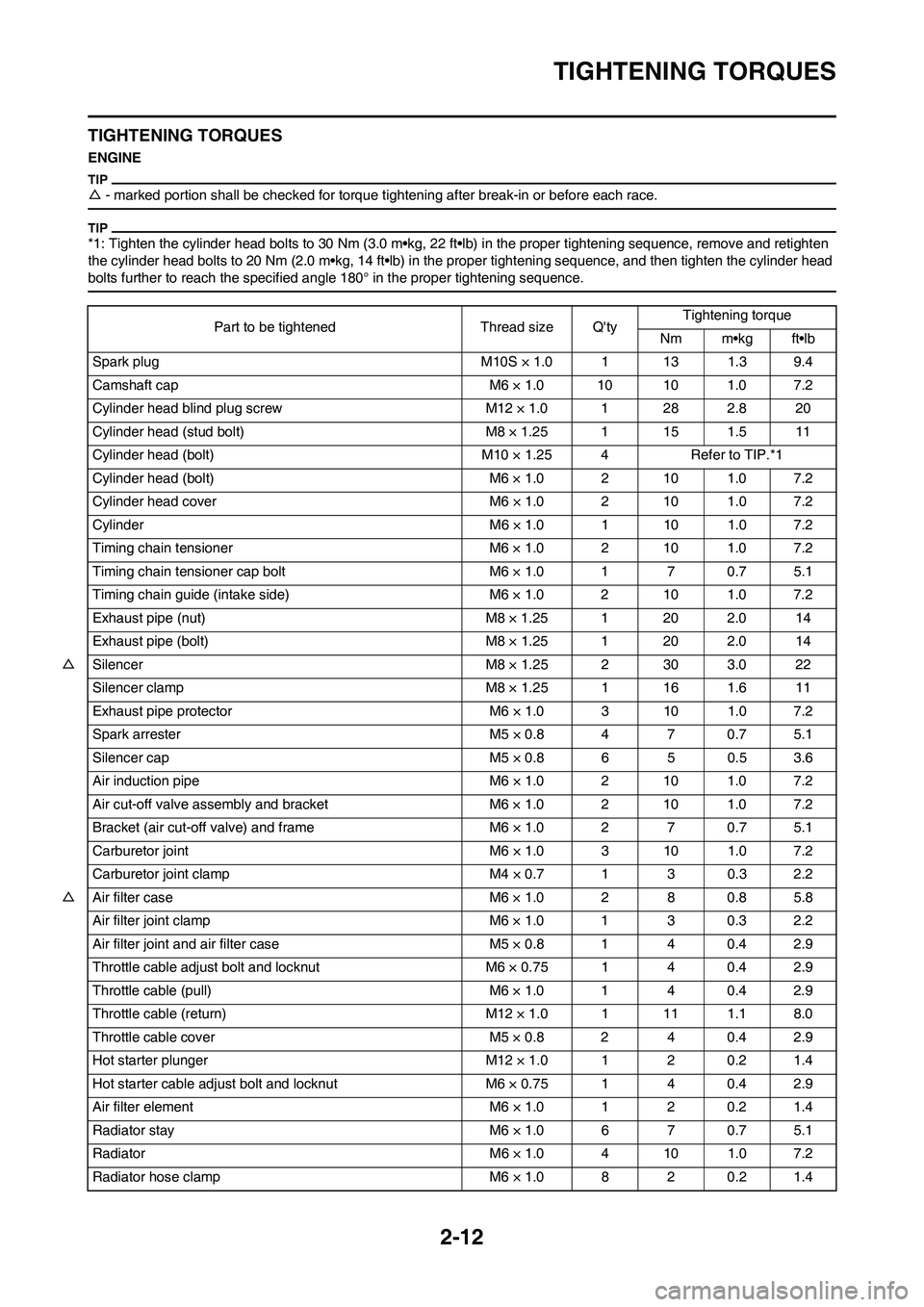
TIGHTENING TORQUES
TIGHTENING TORQUES
ENGINE
△- marked portion shall be checked for torque tightening after break-in or before each race.
*1: Tighten the cylinder head bolts to 30 Nm (3.0 m•kg, 22 ft•lb) in the proper tightening sequence, remove and retighten
the cylinder head bolts to 20 Nm (2.0 m•kg, 14 ft•lb) in the proper tightening sequence, and then tighten the cylinder head
bolts further to reach the specified angle 180° in the proper tightening sequence.
Part to be tightened Thread size Q'tyTightening torque
Nm m•kg ft•lb
Spark plug M10S × 1.0 1 13 1.3 9.4
Camshaft cap M6 × 1.0 10 10 1.0 7.2
Cylinder head blind plug screw M12 × 1.0 1 28 2.8 20
Cylinder head (stud bolt) M8 × 1.25 1 15 1.5 11
Cylinder head (bolt) M10 × 1.25 4 Refer to TIP.*1
Cylinder head (bolt) M6 × 1.0 2 10 1.0 7.2
Cylinder head cover M6 × 1.0 2 10 1.0 7.2
Cylinder M6 × 1.0 1 10 1.0 7.2
Timing chain tensioner M6 × 1.0 2 10 1.0 7.2
Timing chain tensioner cap bolt M6 × 1.0 1 7 0.7 5.1
Timing chain guide (intake side) M6 × 1.0 2 10 1.0 7.2
Exhaust pipe (nut) M8 × 1.25 1 20 2.0 14
Exhaust pipe (bolt) M8 × 1.25 1 20 2.0 14
△Silencer M8 × 1.25 2 30 3.0 22
Silencer clamp M8 × 1.25 1 16 1.6 11
Exhaust pipe protector M6 × 1.0 3 10 1.0 7.2
Spark arrester M5 × 0.8 4 7 0.7 5.1
Silencer cap M5 × 0.8 6 5 0.5 3.6
Air induction pipe M6 × 1.0 2 10 1.0 7.2
Air cut-off valve assembly and bracket M6 × 1.0 2 10 1.0 7.2
Bracket (air cut-off valve) and frame M6 × 1.0 2 7 0.7 5.1
Carburetor joint M6 × 1.0 3 10 1.0 7.2
Carburetor joint clamp M4 × 0.7 1 3 0.3 2.2
△Air filter case M6 × 1.0 2 8 0.8 5.8
Air filter joint clamp M6 × 1.0 1 3 0.3 2.2
Air filter joint and air filter case M5 × 0.8 1 4 0.4 2.9
Throttle cable adjust bolt and locknut M6 × 0.75 1 4 0.4 2.9
Throttle cable (pull) M6 × 1.0 1 4 0.4 2.9
Throttle cable (return) M12 × 1.0 1 11 1.1 8.0
Throttle cable cover M5 × 0.8 2 4 0.4 2.9
Hot starter plunger M12 × 1.0 1 2 0.2 1.4
Hot starter cable adjust bolt and locknut M6 × 0.75 1 4 0.4 2.9
Air filter element M6 × 1.0 1 2 0.2 1.4
Radiator stay M6 × 1.0 6 7 0.7 5.1
Radiator M6 × 1.0 4 10 1.0 7.2
Radiator hose clamp M6 × 1.0 8 2 0.2 1.4
Page 42 of 226
2-15
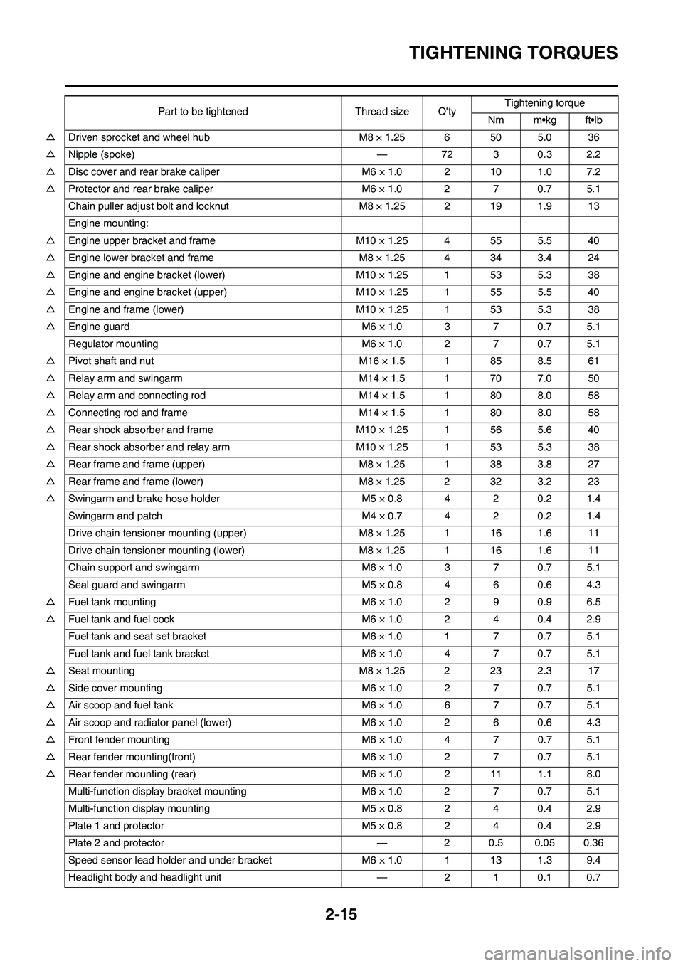
TIGHTENING TORQUES
△Driven sprocket and wheel hub M8 × 1.25 6 50 5.0 36
△Nipple (spoke) — 72 3 0.3 2.2
△Disc cover and rear brake caliper M6 × 1.0 2 10 1.0 7.2
△Protector and rear brake caliper M6 × 1.0 2 7 0.7 5.1
Chain puller adjust bolt and locknut M8 × 1.25 2 19 1.9 13
Engine mounting:
△Engine upper bracket and frame M10 × 1.25 4 55 5.5 40
△Engine lower bracket and frame M8 × 1.25 4 34 3.4 24
△Engine and engine bracket (lower) M10 × 1.25 1 53 5.3 38
△Engine and engine bracket (upper) M10 × 1.25 1 55 5.5 40
△Engine and frame (lower) M10 × 1.25 1 53 5.3 38
△Engine guard M6 × 1.0 3 7 0.7 5.1
Regulator mounting M6 × 1.0 2 7 0.7 5.1
△Pivot shaft and nut M16 × 1.5 1 85 8.5 61
△Relay arm and swingarm M14 × 1.5 1 70 7.0 50
△Relay arm and connecting rod M14 × 1.5 1 80 8.0 58
△Connecting rod and frame M14 × 1.5 1 80 8.0 58
△Rear shock absorber and frame M10 × 1.25 1 56 5.6 40
△Rear shock absorber and relay arm M10 × 1.25 1 53 5.3 38
△Rear frame and frame (upper) M8 × 1.25 1 38 3.8 27
△Rear frame and frame (lower) M8 × 1.25 2 32 3.2 23
△Swingarm and brake hose holder M5 × 0.8 4 2 0.2 1.4
Swingarm and patch M4 × 0.7 4 2 0.2 1.4
Drive chain tensioner mounting (upper) M8 × 1.25 1 16 1.6 11
Drive chain tensioner mounting (lower) M8 × 1.25 1 16 1.6 11
Chain support and swingarm M6 × 1.0 3 7 0.7 5.1
Seal guard and swingarm M5 × 0.8 4 6 0.6 4.3
△Fuel tank mounting M6 × 1.0 2 9 0.9 6.5
△Fuel tank and fuel cock M6 × 1.0 2 4 0.4 2.9
Fuel tank and seat set bracket M6 × 1.0 1 7 0.7 5.1
Fuel tank and fuel tank bracket M6 × 1.0 4 7 0.7 5.1
△Seat mounting M8 × 1.25 2 23 2.3 17
△Side cover mounting M6 × 1.0 2 7 0.7 5.1
△Air scoop and fuel tank M6 × 1.0 6 7 0.7 5.1
△Air scoop and radiator panel (lower) M6 × 1.0 2 6 0.6 4.3
△Front fender mounting M6 × 1.0 4 7 0.7 5.1
△Rear fender mounting(front) M6 × 1.0 2 7 0.7 5.1
△Rear fender mounting (rear) M6 × 1.0 2 11 1.1 8.0
Multi-function display bracket mounting M6 × 1.0 2 7 0.7 5.1
Multi-function display mounting M5 × 0.8 2 4 0.4 2.9
Plate 1 and protector M5 × 0.8 2 4 0.4 2.9
Plate 2 and protector — 2 0.5 0.05 0.36
Speed sensor lead holder and under bracket M6 × 1.0 1 13 1.3 9.4
Headlight body and headlight unit — 2 1 0.1 0.7Part to be tightened Thread size Q'tyTightening torque
Nm m•kg ft•lb
Page 72 of 226
3-17
ENGINE
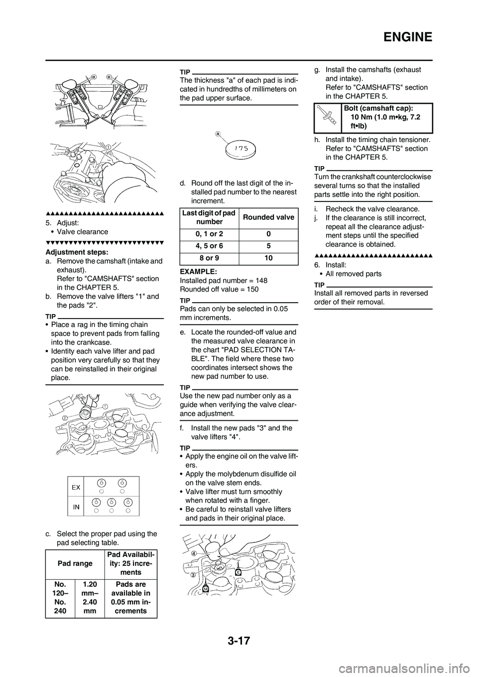
5. Adjust:
• Valve clearance
Adjustment steps:
a. Remove the camshaft (intake and
exhaust).
Refer to "CAMSHAFTS" section
in the CHAPTER 5.
b. Remove the valve lifters "1" and
the pads "2".
• Place a rag in the timing chain
space to prevent pads from falling
into the crankcase.
• Identity each valve lifter and pad
position very carefully so that they
can be reinstalled in their original
place.
c. Select the proper pad using the
pad selecting table.
The thickness "a" of each pad is indi-
cated in hundredths of millimeters on
the pad upper surface.
d. Round off the last digit of the in-
stalled pad number to the nearest
increment.
EXAMPLE:
Installed pad number = 148
Rounded off value = 150
Pads can only be selected in 0.05
mm increments.
e. Locate the rounded-off value and
the measured valve clearance in
the chart "PAD SELECTION TA-
BLE". The field where these two
coordinates intersect shows the
new pad number to use.
Use the new pad number only as a
guide when verifying the valve clear-
ance adjustment.
f. Install the new pads "3" and the
valve lifters "4".
• Apply the engine oil on the valve lift-
ers.
• Apply the molybdenum disulfide oil
on the valve stem ends.
• Valve lifter must turn smoothly
when rotated with a finger.
• Be careful to reinstall valve lifters
and pads in their original place.
g. Install the camshafts (exhaust
and intake).
Refer to "CAMSHAFTS" section
in the CHAPTER 5.
h. Install the timing chain tensioner.
Refer to "CAMSHAFTS" section
in the CHAPTER 5.
Turn the crankshaft counterclockwise
several turns so that the installed
parts settle into the right position.
i. Recheck the valve clearance.
j. If the clearance is still incorrect,
repeat all the clearance adjust-
ment steps until the specified
clearance is obtained.
6. Install:
• All removed parts
Install all removed parts in reversed
order of their removal.
Pad rangePad Availabil-
ity: 25 incre-
ments
No.
120–
No.
2401.20
mm–
2.40
mmPads are
available in
0.05 mm in-
crements
Last digit of pad
numberRounded valve
0, 1 or 2 0
4, 5 or 6 5
8 or 9 10
Bolt (camshaft cap):
10 Nm (1.0 m•kg, 7.2
ft•lb)
Page 77 of 226
3-22
CHASSIS
3. Inspect:
• Brake fluid level
Refer to "CHECKING THE
BRAKE FLUID LEVEL" section.
4. Check:
• Brake pedal operation
A softy or spongy feeling→Bleed
brake system.
Refer to "BLEEDING THE HY-
DRAULIC BRAKE SYSTEM" sec-
tion.
CHECKING THE REAR BRAKE
PAD INSULATOR
1. Remove:
• Brake pad
Refer to "CHECKING AND RE-
PLACING THE REAR BRAKE
PADS" section.
2. Inspect:
• Rear brake pad insulator "1"
Damage→Replace.
CHECKING THE BRAKE FLUID
LEVEL
1. Place the brake master cylinder
so that its top is in a horizontal po-
sition.
2. Inspect:
• Brake fluid level
Fluid at lower level→Fill up.
• Use only designated quality
brake fluid to avoid poor brake
performance.
• Refill with same type and brand
of brake fluid; mixing fluids
could result in poor brake perfor-
mance.
• Be sure that water or other con-
taminants do not enter master
cylinder when refilling.
• Clean up spilled fluid immediate-
ly to avoid erosion of painted
surfaces or plastic parts.
a. Lower level
A. Front
B. Rear
CHECKING THE SPROCKET
1. Inspect:
• Sprocket teeth "a"
Excessive wear→Replace.
Replace the drive sprocket, rear
wheel sprocket and drive chain as a
set.
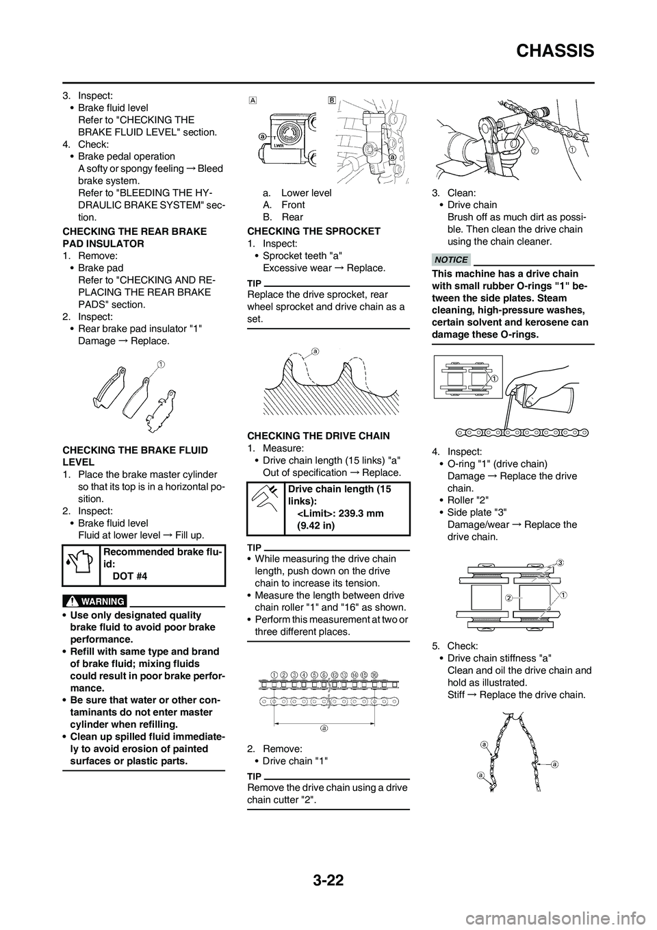
CHECKING THE DRIVE CHAIN
1. Measure:
• Drive chain length (15 links) "a"
Out of specification→Replace.
• While measuring the drive chain
length, push down on the drive
chain to increase its tension.
• Measure the length between drive
chain roller "1" and "16" as shown.
• Perform this measurement at two or
three different places.
2. Remove:
• Drive chain "1"
Remove the drive chain using a drive
chain cutter "2".
3. Clean:
• Drive chain
Brush off as much dirt as possi-
ble. Then clean the drive chain
using the chain cleaner.
This machine has a drive chain
with small rubber O-rings "1" be-
tween the side plates. Steam
cleaning, high-pressure washes,
certain solvent and kerosene can
damage these O-rings.
4. Inspect:
• O-ring "1" (drive chain)
Damage→Replace the drive
chain.
•Roller "2"
• Side plate "3"
Damage/wear→Replace the
drive chain.
5. Check:
• Drive chain stiffness "a"
Clean and oil the drive chain and
hold as illustrated.
Stiff→Replace the drive chain. Recommended brake flu-
id:
DOT #4
Drive chain length (15
links):
(9.42 in)
Page 114 of 226

5-16
CAMSHAFTS
REMOVING THE CAMSHAFTS
Order Part name Q'ty Remarks
1 Timing mark accessing screw1 Refer to removal section.
2 Crankshaft end accessing screw 1 Refer to removal section.
3 Timing chain tensioner cap bolt 1 Refer to removal section.
4 Timing chain tensioner 1 Refer to removal section.
5 Gasket 1 Refer to removal section.
6 Bolt (camshaft cap) 10 Refer to removal section.
7 Camshaft cap 2 Refer to removal section.
8 Clip 2 Refer to removal section.
9 Exhaust camshaft 1 Refer to removal section.
10 Intake camshaft 1 Refer to removal section.
Page 115 of 226
5-17
CAMSHAFTS
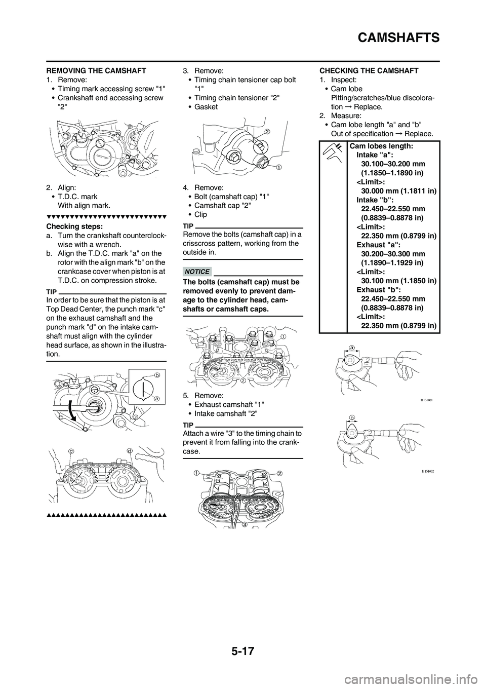
REMOVING THE CAMSHAFT
1. Remove:
• Timing mark accessing screw "1"
• Crankshaft end accessing screw
"2"
2. Align:
• T.D.C. mark
With align mark.
Checking steps:
a. Turn the crankshaft counterclock-
wise with a wrench.
b. Align the T.D.C. mark "a" on the
rotor with the align mark "b" on the
crankcase cover when piston is at
T.D.C. on compression stroke.
In order to be sure that the piston is at
Top Dead Center, the punch mark "c"
on the exhaust camshaft and the
punch mark "d" on the intake cam-
shaft must align with the cylinder
head surface, as shown in the illustra-
tion.
3. Remove:
• Timing chain tensioner cap bolt
"1"
• Timing chain tensioner "2"
• Gasket
4. Remove:
• Bolt (camshaft cap) "1"
• Camshaft cap "2"
• Clip
Remove the bolts (camshaft cap) in a
crisscross pattern, working from the
outside in.
The bolts (camshaft cap) must be
removed evenly to prevent dam-
age to the cylinder head, cam-
shafts or camshaft caps.
5. Remove:
• Exhaust camshaft "1"
• Intake camshaft "2"
Attach a wire "3" to the timing chain to
prevent it from falling into the crank-
case.
CHECKING THE CAMSHAFT
1. Inspect:
•Cam lobe
Pitting/scratches/blue discolora-
tion→Replace.
2. Measure:
• Cam lobe length "a" and "b"
Out of specification→Replace.
Cam lobes length:
Intake "a":
30.100–30.200 mm
(1.1850–1.1890 in)
30.000 mm (1.1811 in)
Intake "b":
22.450–22.550 mm
(0.8839–0.8878 in)
22.350 mm (0.8799 in)
Exhaust "a":
30.200–30.300 mm
(1.1890–1.1929 in)
30.100 mm (1.1850 in)
Exhaust "b":
22.450–22.550 mm
(0.8839–0.8878 in)
22.350 mm (0.8799 in)
Page 116 of 226
5-18
CAMSHAFTS
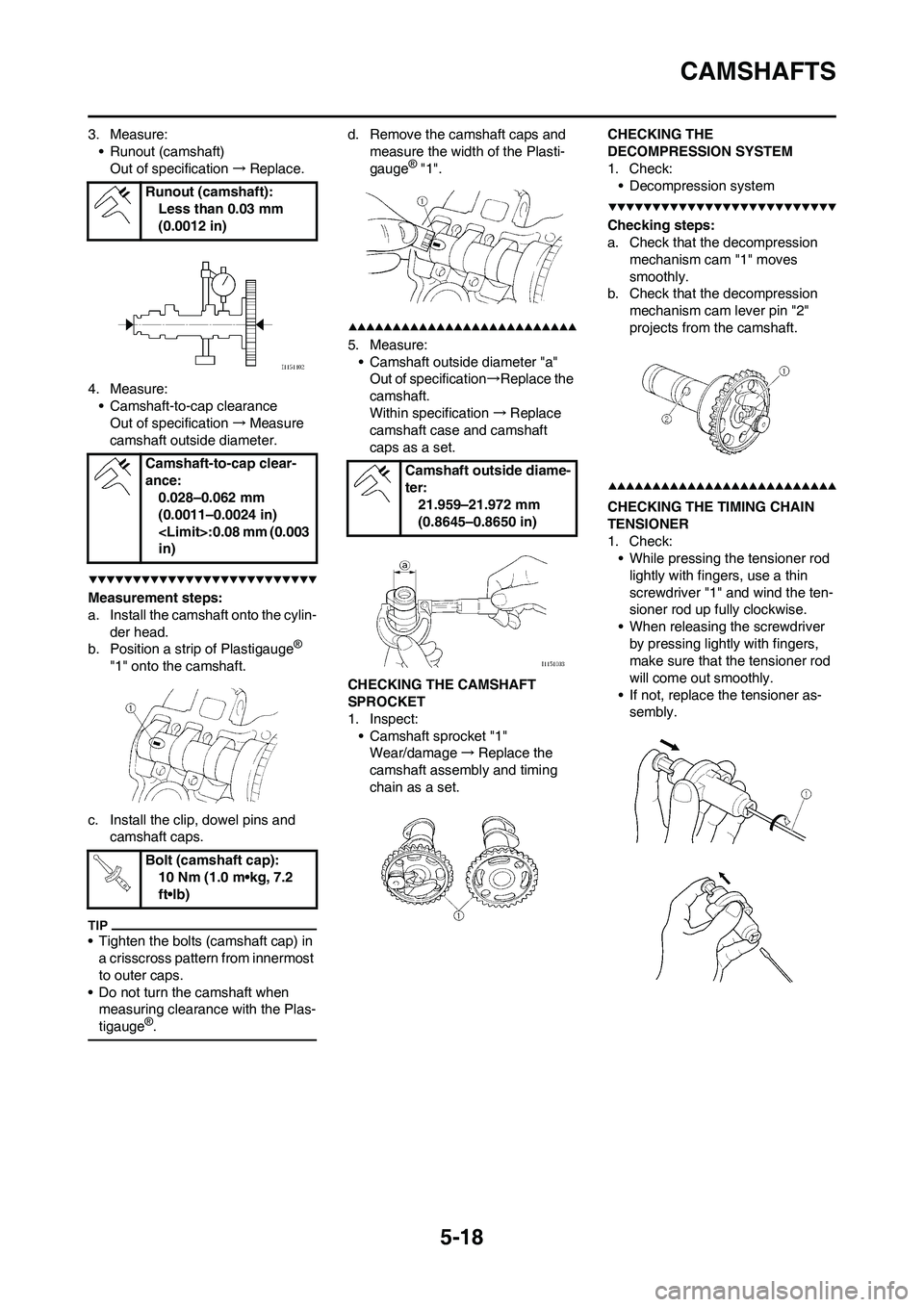
3. Measure:
• Runout (camshaft)
Out of specification→Replace.
4. Measure:
• Camshaft-to-cap clearance
Out of specification→Measure
camshaft outside diameter.
Measurement steps:
a. Install the camshaft onto the cylin-
der head.
b. Position a strip of Plastigauge
®
"1" onto the camshaft.
c. Install the clip, dowel pins and
camshaft caps.
• Tighten the bolts (camshaft cap) in
a crisscross pattern from innermost
to outer caps.
• Do not turn the camshaft when
measuring clearance with the Plas-
tigauge
®.
d. Remove the camshaft caps and
measure the width of the Plasti-
gauge
® "1".
5. Measure:
• Camshaft outside diameter "a"
Out of specification→Replace the
camshaft.
Within specification→Replace
camshaft case and camshaft
caps as a set.
CHECKING THE CAMSHAFT
SPROCKET
1. Inspect:
• Camshaft sprocket "1"
Wear/damage→Replace the
camshaft assembly and timing
chain as a set.CHECKING THE
DECOMPRESSION SYSTEM
1. Check:
• Decompression system
Checking steps:
a. Check that the decompression
mechanism cam "1" moves
smoothly.
b. Check that the decompression
mechanism cam lever pin "2"
projects from the camshaft.
CHECKING THE TIMING CHAIN
TENSIONER
1. Check:
• While pressing the tensioner rod
lightly with fingers, use a thin
screwdriver "1" and wind the ten-
sioner rod up fully clockwise.
• When releasing the screwdriver
by pressing lightly with fingers,
make sure that the tensioner rod
will come out smoothly.
• If not, replace the tensioner as-
sembly. Runout (camshaft):
Less than 0.03 mm
(0.0012 in)
Camshaft-to-cap clear-
ance:
0.028–0.062 mm
(0.0011–0.0024 in)
in)
Bolt (camshaft cap):
10 Nm (1.0 m•kg, 7.2
ft•lb)
Camshaft outside diame-
ter:
21.959–21.972 mm
(0.8645–0.8650 in)
Page 117 of 226
5-19
CAMSHAFTS
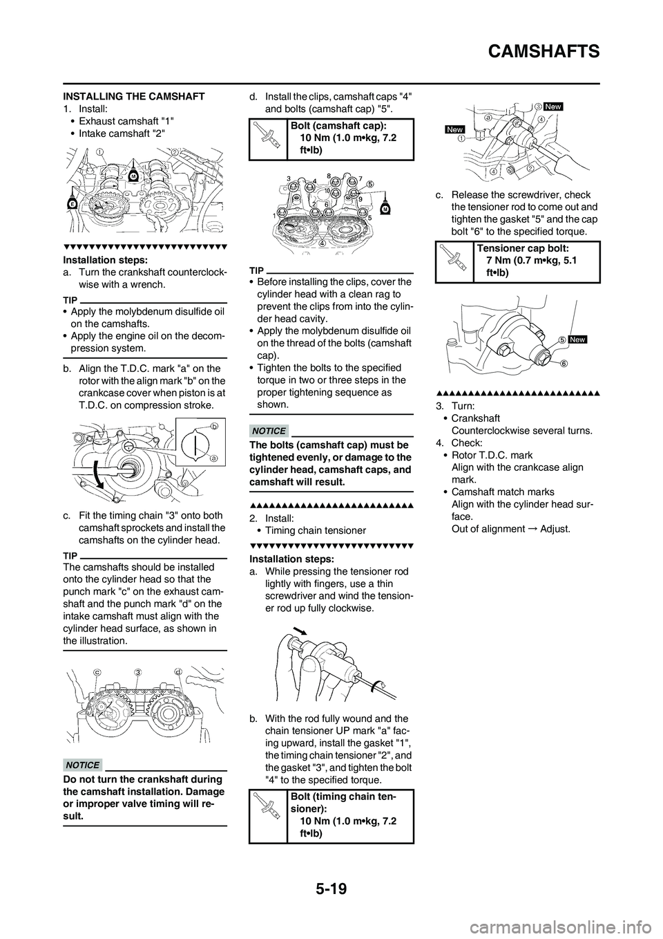
INSTALLING THE CAMSHAFT
1. Install:
• Exhaust camshaft "1"
• Intake camshaft "2"
Installation steps:
a. Turn the crankshaft counterclock-
wise with a wrench.
• Apply the molybdenum disulfide oil
on the camshafts.
• Apply the engine oil on the decom-
pression system.
b. Align the T.D.C. mark "a" on the
rotor with the align mark "b" on the
crankcase cover when piston is at
T.D.C. on compression stroke.
c. Fit the timing chain "3" onto both
camshaft sprockets and install the
camshafts on the cylinder head.
The camshafts should be installed
onto the cylinder head so that the
punch mark "c" on the exhaust cam-
shaft and the punch mark "d" on the
intake camshaft must align with the
cylinder head surface, as shown in
the illustration.
Do not turn the crankshaft during
the camshaft installation. Damage
or improper valve timing will re-
sult.
d. Install the clips, camshaft caps "4"
and bolts (camshaft cap) "5".
• Before installing the clips, cover the
cylinder head with a clean rag to
prevent the clips from into the cylin-
der head cavity.
• Apply the molybdenum disulfide oil
on the thread of the bolts (camshaft
cap).
• Tighten the bolts to the specified
torque in two or three steps in the
proper tightening sequence as
shown.
The bolts (camshaft cap) must be
tightened evenly, or damage to the
cylinder head, camshaft caps, and
camshaft will result.
2. Install:
• Timing chain tensioner
Installation steps:
a. While pressing the tensioner rod
lightly with fingers, use a thin
screwdriver and wind the tension-
er rod up fully clockwise.
b. With the rod fully wound and the
chain tensioner UP mark "a" fac-
ing upward, install the gasket "1",
the timing chain tensioner "2", and
the gasket "3", and tighten the bolt
"4" to the specified torque.c. Release the screwdriver, check
the tensioner rod to come out and
tighten the gasket "5" and the cap
bolt "6" to the specified torque.
3. Turn:
• Crankshaft
Counterclockwise several turns.
4. Check:
• Rotor T.D.C. mark
Align with the crankcase align
mark.
• Camshaft match marks
Align with the cylinder head sur-
face.
Out of alignment→Adjust.
Bolt (camshaft cap):
10 Nm (1.0 m•kg, 7.2
ft•lb)
Bolt (timing chain ten-
sioner):
10 Nm (1.0 m•kg, 7.2
ft•lb)
Tensioner cap bolt:
7 Nm (0.7 m•kg, 5.1
ft•lb)
Page 194 of 226
6-31
SWINGARM
SWINGARM
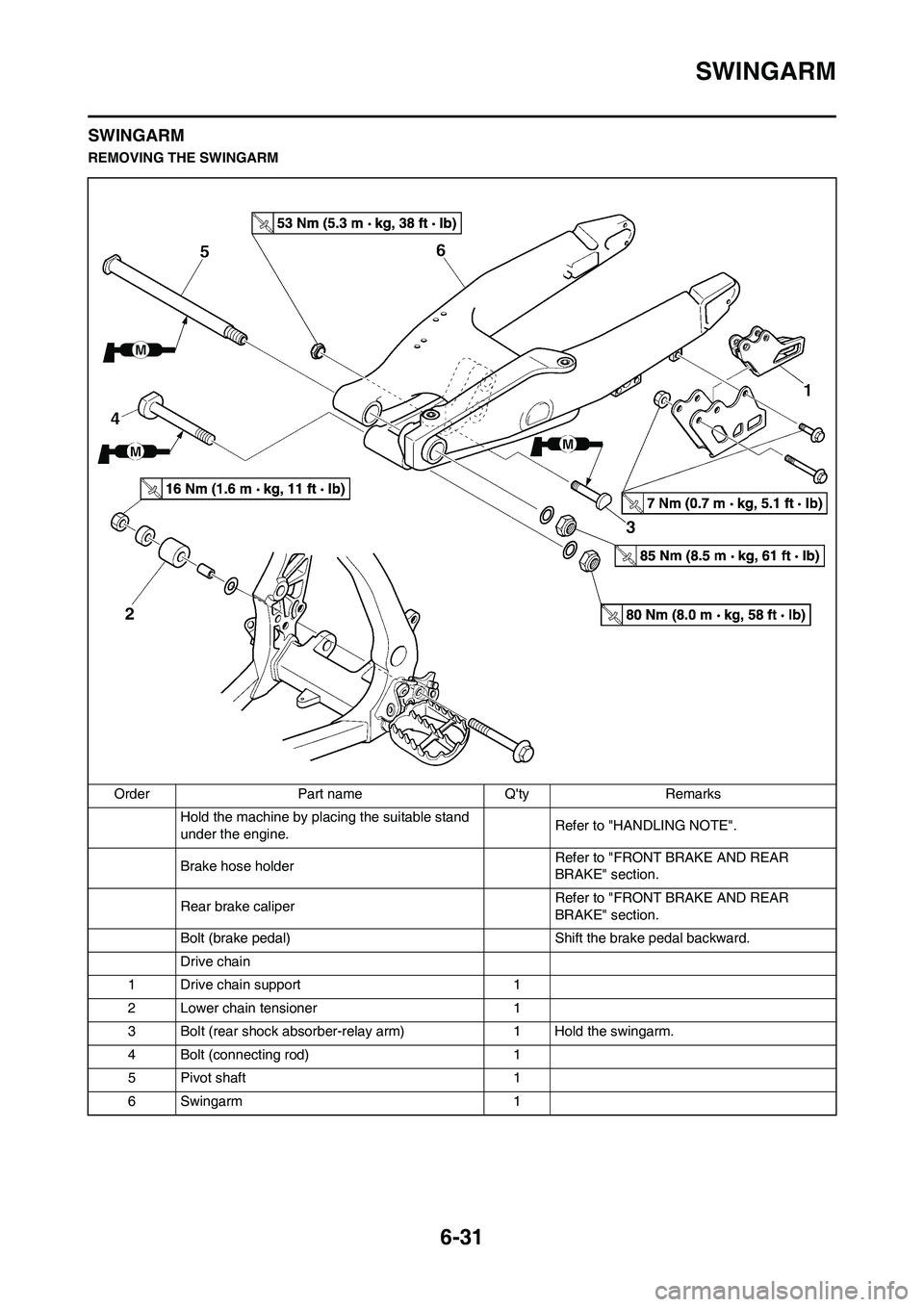
REMOVING THE SWINGARM
Order Part name Q'ty Remarks
Hold the machine by placing the suitable stand
under the engine.Refer to "HANDLING NOTE".
Brake hose holder Refer to "FRONT BRAKE AND REAR
BRAKE" section.
Rear brake caliperRefer to "FRONT BRAKE AND REAR
BRAKE" section.
Bolt (brake pedal) Shift the brake pedal backward.
Drive chain
1 Drive chain support 1
2 Lower chain tensioner 1
3 Bolt (rear shock absorber-relay arm) 1 Hold the swingarm.
4 Bolt (connecting rod) 1
5 Pivot shaft 1
6 Swingarm 1
Page 198 of 226
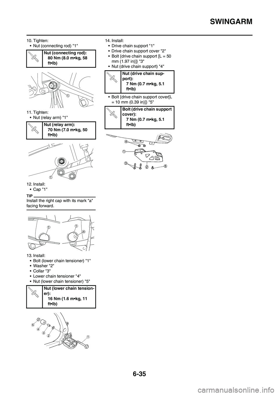
6-35
SWINGARM
10. Tighten:
• Nut (connecting rod) "1"
11. Tighten:
• Nut (relay arm) "1"
12. Install:
•Cap "1"
Install the right cap with its mark "a"
facing forward.
13. Install:
• Bolt (lower chain tensioner) "1"
• Washer "2"
•Collar "3"
• Lower chain tensioner "4"
• Nut (lower chain tensioner) "5"14. Install:
• Drive chain support "1"
• Drive chain support cover "2"
• Bolt {drive chain support [L = 50
mm (1.97 in)]} "3"
• Nut (drive chain support) "4"
• Bolt {drive chain support cover[L
= 10 mm (0.39 in)]} "5" Nut (connecting rod):
80 Nm (8.0 m•kg, 58
ft•lb)
Nut (relay arm):
70 Nm (7.0 m•kg, 50
ft•lb)
Nut (lower chain tension-
er):
16 Nm (1.6 m•kg, 11
ft•lb)
Nut (drive chain sup-
port):
7 Nm (0.7 m•kg, 5.1
ft•lb)
Bolt (drive chain support
cover):
7 Nm (0.7 m•kg, 5.1
ft•lb)