display YAMAHA WR 450F 2009 Owners Manual
[x] Cancel search | Manufacturer: YAMAHA, Model Year: 2009, Model line: WR 450F, Model: YAMAHA WR 450F 2009Pages: 226, PDF Size: 14.26 MB
Page 10 of 226
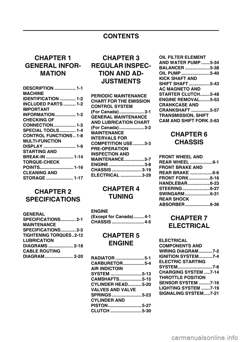
CONTENTS
CHAPTER 1
GENERAL INFOR-
MATION
DESCRIPTION ................. 1-1
MACHINE
IDENTIFICATION ............. 1-2
INCLUDED PARTS .......... 1-2
IMPORTANT
INFORMATION................. 1-2
CHECKING OF
CONNECTION .................. 1-3
SPECIAL TOOLS ............. 1-4
CONTROL FUNCTIONS .. 1-8
MULTI-FUNCTION
DISPLAY .......................... 1-9
STARTING AND
BREAK-IN ...................... 1-14
TORQUE-CHECK
POINTS........................... 1-16
CLEANING AND
STORAGE ...................... 1-17
CHAPTER 2
SPECIFICATIONS
GENERAL
SPECIFICATIONS ............ 2-1
MAINTENANCE
SPECIFICATIONS ............ 2-3
TIGHTENING TORQUES .. 2-12
LUBRICATION
DIAGRAMS .................... 2-18
CABLE ROUTING
DIAGRAM ....................... 2-20
CHAPTER 3
REGULAR INSPEC-
TION AND AD-
JUSTMENTS
PERIODIC MAINTENANCE
CHART FOR THE EMISSION
CONTROL SYSTEM
(For Canada) .................... 3-1
GENERAL MAINTENANCE
AND LUBRICATION CHART
(For Canada) .................... 3-2
MAINTENANCE
INTERVALS FOR
COMPETITION USE ......... 3-3
PRE-OPERATION
INSPECTION AND
MAINTENANCE................ 3-7
ENGINE ............................ 3-8
CHASSIS ........................ 3-19
ELECTRICAL ................. 3-29
CHAPTER 4
TUNING
ENGINE
(Except for Canada) ........ 4-1
CHASSIS .......................... 4-5
CHAPTER 5
ENGINE
RADIATOR ....................... 5-1
CARBURETOR................. 5-4
AIR INDICTOIN
SYSTEM ......................... 5-13
CAMSHAFTS.................. 5-15
CYLINDER HEAD........... 5-20
VALVES AND VALVE
SPRINGS ........................ 5-23
CYLINDER AND
PISTON ........................... 5-27
CLUTCH ......................... 5-30OIL FILTER ELEMENT
AND WATER PUMP .......5-34
BALANCER ....................5-38
OIL PUMP .......................5-40
KICK SHAFT AND
SHIFT SHAFT .................5-43
AC MAGNETO AND
STARTER CLUTCH........5-48
ENGINE REMOVAL........5-53
CRANKCASE AND
CRANKSHAFT ...............5-57
TRANSMISSION, SHIFT
CAM AND SHIFT FORK .5-63
CHAPTER 6
CHASSIS
FRONT WHEEL AND
REAR WHEEL ..................6-1
FRONT BRAKE AND
REAR BRAKE ..................6-6
FRONT FORK .................6-16
HANDLEBAR..................6-23
STEERING ......................6-27
SWINGARM ....................6-31
REAR SHOCK
ABSORBER ....................6-36
CHAPTER 7
ELECTRICAL
ELECTRICAL
COMPONENTS AND
WIRING DIAGRAM ...........7-2
IGNITION SYSTEM...........7-4
ELECTRIC STARTING
SYSTEM............................7-6
CHARGING SYSTEM .....7-14
THROTTLE POSITION
SENSOR SYSTEM .........7-16
LIGHTING SYSTEM .......7-19
SIGNALING SYSTEM.....7-21
Page 11 of 226
1-1
DESCRIPTION
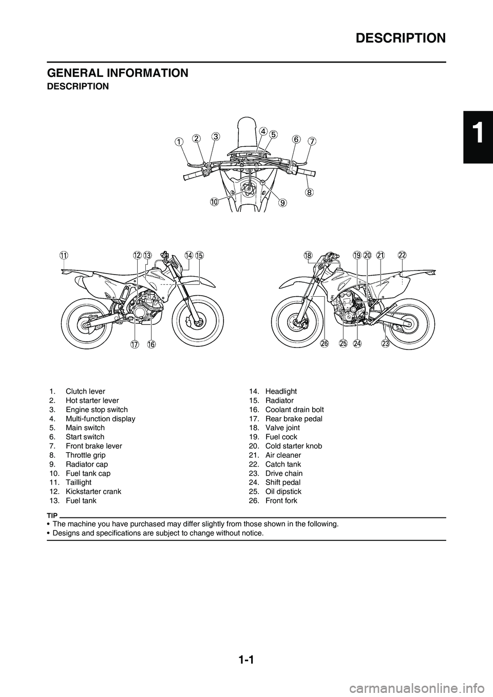
GENERAL INFORMATION
DESCRIPTION
• The machine you have purchased may differ slightly from those shown in the following.
• Designs and specifications are subject to change without notice.
1. Clutch lever
2. Hot starter lever
3. Engine stop switch
4. Multi-function display
5. Main switch
6. Start switch
7. Front brake lever
8. Throttle grip
9. Radiator cap
10. Fuel tank cap
11. Taillight
12. Kickstarter crank
13. Fuel tank14. Headlight
15. Radiator
16. Coolant drain bolt
17. Rear brake pedal
18. Valve joint
19. Fuel cock
20. Cold starter knob
21. Air cleaner
22. Catch tank
23. Drive chain
24. Shift pedal
25. Oil dipstick
26. Front fork
1
Page 19 of 226
1-9
MULTI-FUNCTION DISPLAY
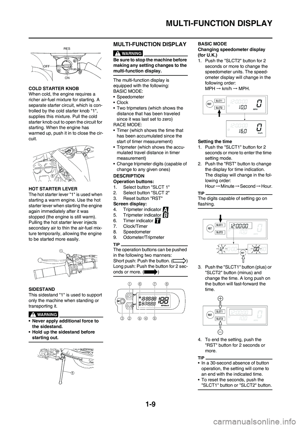
COLD STARTER KNOB
When cold, the engine requires a
richer air-fuel mixture for starting. A
separate starter circuit, which is con-
trolled by the cold starter knob "1",
supplies this mixture. Pull the cold
starter knob out to open the circuit for
starting. When the engine has
warmed up, push it in to close the cir-
cuit.
HOT STARTER LEVER
The hot starter lever "1" is used when
starting a warm engine. Use the hot
starter lever when starting the engine
again immediately after it was
stopped (the engine is still warm).
Pulling the hot starter lever injects
secondary air to thin the air-fuel mix-
ture temporarily, allowing the engine
to be started more easily.
SIDESTAND
This sidestand "1" is used to support
only the machine when standing or
transporting it.
• Never apply additional force to
the sidestand.
• Hold up the sidestand before
starting out.
MULTI-FUNCTION DISPLAY
Be sure to stop the machine before
making any setting changes to the
multi-function display.
The multi-function display is
equipped with the following:
BASIC MODE:
• Speedometer
•Clock
• Two tripmeters (which shows the
distance that has been traveled
since it was last set to zero)
RACE MODE:
• Timer (which shows the time that
has been accumulated since the
start of timer measurement)
• Tripmeter (which shows the accu-
mulated travel distance in timer
measurement)
• Change tripmeter digits (capable of
change to any given ones)
DESCRIPTION
Operation buttons:
1. Select button "SLCT 1"
2. Select button "SLCT 2"
3. Reset button "RST"
Screen display:
4. Tripmeter indicator
5. Tripmeter indicator
6. Timer indicator
7. Clock/Timer
8. Speedometer
9. Odometer/Tripmeter
The operation buttons can be pushed
in the following two manners:
Short push: Push the button. ( )
Long push: Push the button for 2 sec-
onds or more. ( )
BASIC MODE
Changing speedometer display
(for U.K.)
1. Push the "SLCT2" button for 2
seconds or more to change the
speedometer units. The speed-
ometer display will change in the
following order:
MPH→km/h→MPH.
Setting the time
1. Push the "SLCT1" button for 2
seconds or more to enter the time
setting mode.
2. Push the "RST" button to change
the display for time indication.
The display will change in the fol-
lowing order:
Hour→Minute→Second→Hour.
The digits capable of setting go on
flashing.
3. Push the "SLCT1" button (plus) or
"SLCT2" button (minus) and
change the time. A long push on
the button will fast-forward the
time.
4. To end the setting, push the
"RST" button for 2 seconds or
more.
• In a 30-second absence of button
operation, the setting will come to
an end with the indicated time.
• To reset the seconds, push the
"SLCT1" button or "SLCT2" button.
Page 20 of 226
1-10
MULTI-FUNCTION DISPLAY
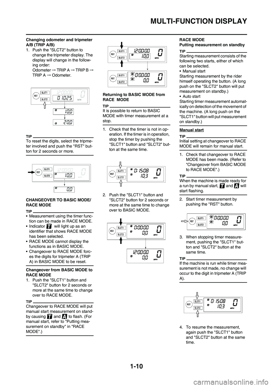
Changing odometer and tripmeter
A/B (TRIP A/B)
1. Push the "SLCT2" button to
change the tripmeter display. The
display will change in the follow-
ing order:
Odometer →TRIP A→TRIP B→
TRIP A→Odometer.
To reset the digits, select the tripme-
ter involved and push the "RST" but-
ton for 2 seconds or more.
CHANGEOVER TO BASIC MODE/
RACE MODE
• Measurement using the timer func-
tion can be made in RACE MODE.
• Indicator will light up as an
identifier that shows RACE MODE
has been selected.
• RACE MODE cannot display the
functions as in BASIC MODE.
• Changeover to RACE MODE forc-
es the digits for tripmeter A (TRIP
A) in BASIC MODE to be reset.
Changeover from BASIC MODE to
RACE MODE
1. Push the "SLCT1" button and
"SLCT2" button for 2 seconds or
more at the same time to change
over to RACE MODE.
Changeover to RACE MODE will put
manual start measurement on stand-
by causing and to flash. (For
manual start, refer to "Putting mea-
surement on standby" in "RACE
MODE".)
Returning to BASIC MODE from
RACE MODE
It is possible to return to BASIC
MODE with timer measurement at a
stop.
1. Check that the timer is not in op-
eration. If the timer is in operation,
stop the timer by pushing the
"SLCT1" button and "SLCT2" but-
ton at the same time.
2. Push the "SLCT1" button and
"SLCT2" button for 2 seconds or
more at the same time to change
over to BASIC MODE.RACE MODE
Putting measurement on standby
Starting measurement consists of the
following two starts, either of which
can be selected.
• Manual start
Starting measurement by the rider
himself operating the button. (A long
push on the "SLCT2" button will put
measurement on standby.)
• Auto start
Starting timer measurement automat-
ically on detection of the movement of
the machine. (A long push on the
"SLCT1" button will put measurement
on standby.)
Manual start
Initial setting at changeover to RACE
MODE will remain for manual start.
1. Check that changeover to RACE
MODE has been made. (Refer to
"Changeover from BASIC MODE
to RACE MODE".)
When the machine is made ready for
a run by manual start, and will
start flashing.
2. Start timer measurement by
pushing the "RST" button.
3. When stopping timer measure-
ment, pushing the "SLCT1" but-
ton and "SLCT2" button at the
same time.
If the machine is run while timer mea-
surement is not made, no change will
occur to the digit in tripmeter A (TRIP
A).
4. To resume the measurement,
again push the "SLCT1" button
and "SLCT2" button at the same
time.
Page 21 of 226
1-11
MULTI-FUNCTION DISPLAY
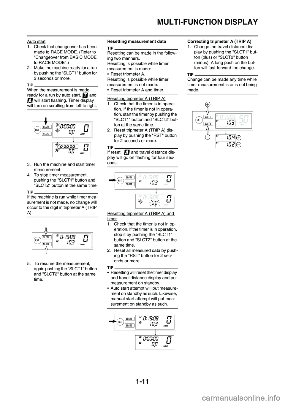
Auto start
1. Check that changeover has been
made to RACE MODE. (Refer to
"Changeover from BASIC MODE
to RACE MODE".)
2. Make the machine ready for a run
by pushing the "SLCT1" button for
2 seconds or more.
When the measurement is made
ready for a run by auto start, and
will start flashing. Timer display
will turn on scrolling from left to right.
3. Run the machine and start timer
measurement.
4. To stop timer measurement,
pushing the "SLCT1" button and
"SLCT2" button at the same time.
If the machine is run while timer mea-
surement is not made, no change will
occur to the digit in tripmeter A (TRIP
A).
5. To resume the measurement,
again pushing the "SLCT1" button
and "SLCT2" button at the same
time.Resetting measurement data
Resetting can be made in the follow-
ing two manners.
Resetting is possible while timer
measurement is made:
• Reset tripmeter A.
Resetting is possible while timer
measurement is not made:
• Reset tripmeter A and timer.
Resetting tripmeter A (TRIP A)
1. Check that the timer is in opera-
tion. If the timer is not in opera-
tion, start the timer by pushing the
"SLCT1" button and "SLCT2" but-
ton at the same time.
2. Reset tripmeter A (TRIP A) dis-
play by pushing the "RST" button
for 2 seconds or more.
If reset, and travel distance dis-
play will go on flashing for four sec-
onds.
Resetting tripmeter A (TRIP A) and
timer
1. Check that the timer is not in op-
eration. If the timer is in operation,
stop it by pushing the "SLCT1"
button and "SLCT2" button at the
same time.
2. Reset all measured data by push-
ing the "RST" button for 2 sec-
onds or more.
• Resetting will reset the timer display
and travel distance display and put
measurement on standby.
• Auto start attempt will put measure-
ment on standby as such. Likewise,
manual start attempt will put mea-
surement on standby as such.
Correcting tripmeter A (TRIP A)
1. Change the travel distance dis-
play by pushing the "SLCT1" but-
ton (plus) or "SLCT2" button
(minus). A long push on the but-
ton will fast-forward the change.
Change can be made any time while
timer measurement is or is not being
made.
Page 22 of 226
1-12
MULTI-FUNCTION DISPLAY
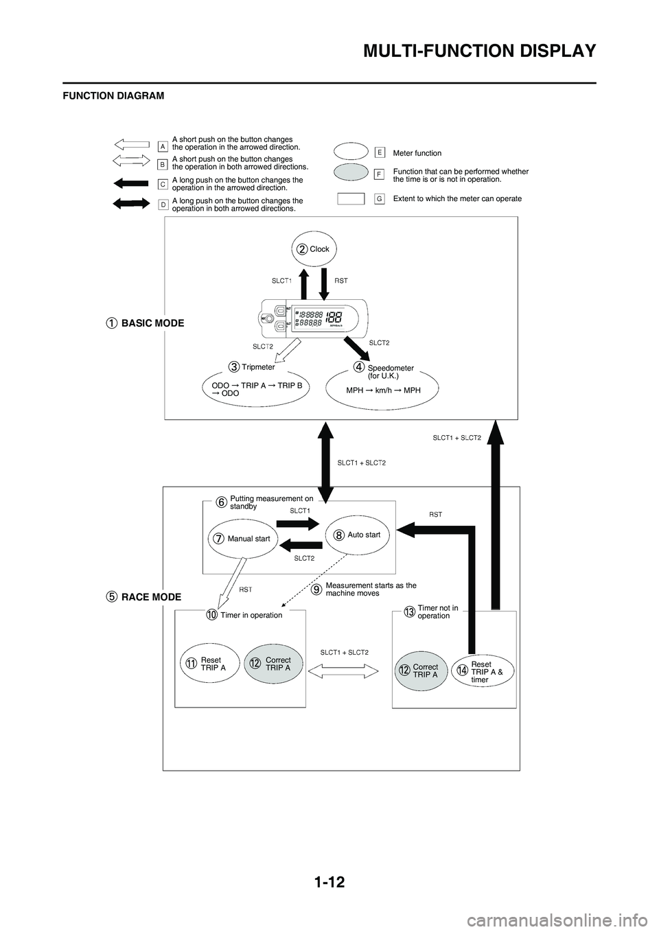
FUNCTION DIAGRAM
A short push on the button changes
the operation in the arrowed direction.
A short push on the button changes
the operation in both arrowed directions.
A long push on the button changes the
operation in the arrowed direction.
A long push on the button changes the
operation in both arrowed directions.Meter function
Function that can be performed whether
the time is or is not in operation.
Extent to which the meter can operate
Clock
BASIC MODE
Tripmeter
ODO TRIP A TRIP B ODO
Speedometer
(for U.K.)
MPH
km/h MPH
Putting measurement on
standby
Manual startAuto start
RACE MODE
Timer in operation
Reset
TRIP ACorrect
TRIP AMeasurement starts as the
machine moves
Timer not in
operation
Correct
TRIP AReset
TRIP A &
timer
Page 23 of 226
1-13
MULTI-FUNCTION DISPLAY
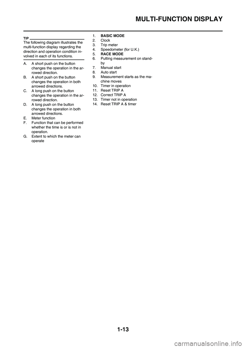
The following diagram illustrates the
multi-function display regarding the
direction and operation condition in-
volved in each of its functions.
A. A short push on the button
changes the operation in the ar-
rowed direction.
B. A short push on the button
changes the operation in both
arrowed directions.
C. A long push on the button
changes the operation in the ar-
rowed direction.
D. A long push on the button
changes the operation in both
arrowed directions.
E. Meter function
F. Function that can be performed
whether the time is or is not in
operation.
G. Extent to which the meter can
operate1.BASIC MODE
2. Clock
3. Trip meter
4. Speedometer (for U.K.)
5.RACE MODE
6. Putting measurement on stand-
by
7. Manual start
8. Auto start
9. Measurement starts as the ma-
chine moves
10. Timer in operation
11. Reset TRIP A
12. Correct TRIP A
13. Timer not in operation
14. Reset TRIP A & timer
Page 42 of 226
2-15
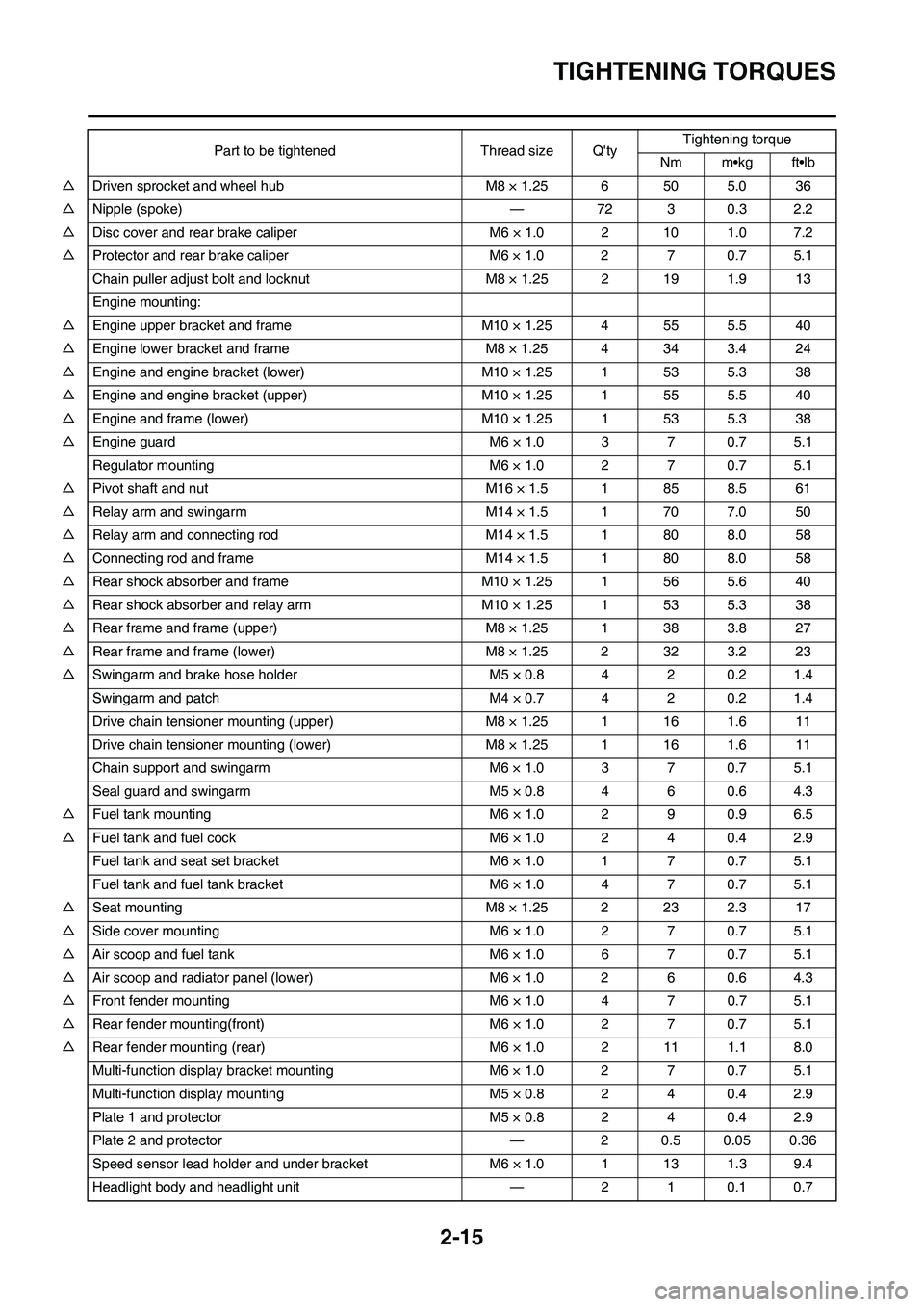
TIGHTENING TORQUES
△Driven sprocket and wheel hub M8 × 1.25 6 50 5.0 36
△Nipple (spoke) — 72 3 0.3 2.2
△Disc cover and rear brake caliper M6 × 1.0 2 10 1.0 7.2
△Protector and rear brake caliper M6 × 1.0 2 7 0.7 5.1
Chain puller adjust bolt and locknut M8 × 1.25 2 19 1.9 13
Engine mounting:
△Engine upper bracket and frame M10 × 1.25 4 55 5.5 40
△Engine lower bracket and frame M8 × 1.25 4 34 3.4 24
△Engine and engine bracket (lower) M10 × 1.25 1 53 5.3 38
△Engine and engine bracket (upper) M10 × 1.25 1 55 5.5 40
△Engine and frame (lower) M10 × 1.25 1 53 5.3 38
△Engine guard M6 × 1.0 3 7 0.7 5.1
Regulator mounting M6 × 1.0 2 7 0.7 5.1
△Pivot shaft and nut M16 × 1.5 1 85 8.5 61
△Relay arm and swingarm M14 × 1.5 1 70 7.0 50
△Relay arm and connecting rod M14 × 1.5 1 80 8.0 58
△Connecting rod and frame M14 × 1.5 1 80 8.0 58
△Rear shock absorber and frame M10 × 1.25 1 56 5.6 40
△Rear shock absorber and relay arm M10 × 1.25 1 53 5.3 38
△Rear frame and frame (upper) M8 × 1.25 1 38 3.8 27
△Rear frame and frame (lower) M8 × 1.25 2 32 3.2 23
△Swingarm and brake hose holder M5 × 0.8 4 2 0.2 1.4
Swingarm and patch M4 × 0.7 4 2 0.2 1.4
Drive chain tensioner mounting (upper) M8 × 1.25 1 16 1.6 11
Drive chain tensioner mounting (lower) M8 × 1.25 1 16 1.6 11
Chain support and swingarm M6 × 1.0 3 7 0.7 5.1
Seal guard and swingarm M5 × 0.8 4 6 0.6 4.3
△Fuel tank mounting M6 × 1.0 2 9 0.9 6.5
△Fuel tank and fuel cock M6 × 1.0 2 4 0.4 2.9
Fuel tank and seat set bracket M6 × 1.0 1 7 0.7 5.1
Fuel tank and fuel tank bracket M6 × 1.0 4 7 0.7 5.1
△Seat mounting M8 × 1.25 2 23 2.3 17
△Side cover mounting M6 × 1.0 2 7 0.7 5.1
△Air scoop and fuel tank M6 × 1.0 6 7 0.7 5.1
△Air scoop and radiator panel (lower) M6 × 1.0 2 6 0.6 4.3
△Front fender mounting M6 × 1.0 4 7 0.7 5.1
△Rear fender mounting(front) M6 × 1.0 2 7 0.7 5.1
△Rear fender mounting (rear) M6 × 1.0 2 11 1.1 8.0
Multi-function display bracket mounting M6 × 1.0 2 7 0.7 5.1
Multi-function display mounting M5 × 0.8 2 4 0.4 2.9
Plate 1 and protector M5 × 0.8 2 4 0.4 2.9
Plate 2 and protector — 2 0.5 0.05 0.36
Speed sensor lead holder and under bracket M6 × 1.0 1 13 1.3 9.4
Headlight body and headlight unit — 2 1 0.1 0.7Part to be tightened Thread size Q'tyTightening torque
Nm m•kg ft•lb
Page 54 of 226
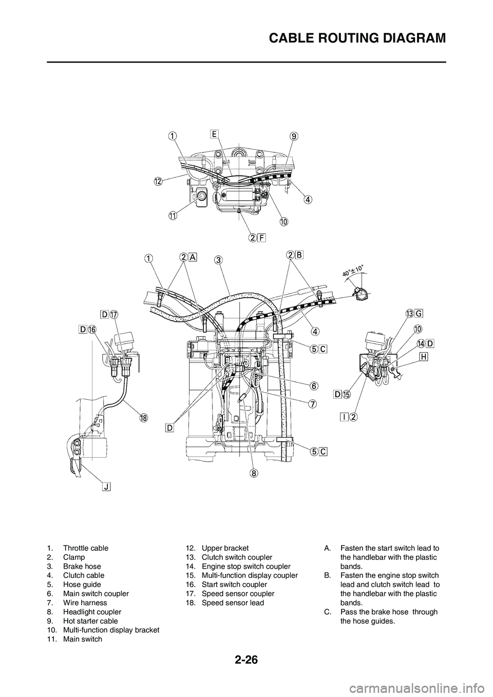
2-26
CABLE ROUTING DIAGRAM
1. Throttle cable
2. Clamp
3. Brake hose
4. Clutch cable
5. Hose guide
6. Main switch coupler
7. Wire harness
8. Headlight coupler
9. Hot starter cable
10. Multi-function display bracket
11. Main switch12. Upper bracket
13. Clutch switch coupler
14. Engine stop switch coupler
15. Multi-function display coupler
16. Start switch coupler
17. Speed sensor coupler
18. Speed sensor leadA. Fasten the start switch lead to
the handlebar with the plastic
bands.
B. Fasten the engine stop switch
lead and clutch switch lead to
the handlebar with the plastic
bands.
C. Pass the brake hose through
the hose guides.
Page 55 of 226
2-27
CABLE ROUTING DIAGRAM
D. Secure the coupler by inserting
it into the multi-function display
bracket.
E. Pass the throttle cables, clutch
cable and hot starter cable be-
tween the upper bracket and
multi-function display bracket.
F. Fasten the multi-function display
leads to the bracket. Cut off the
tie end.
G. Secure the coupler by pushing it
into the hole in the multi-function
display bracket.
H. Secure the wire harness clip by
pushing it into the hole in the
multi-function display bracket on
the inside.
I. Fasten the main switch lead
(wire harness side) to the multi-
function display bracket. Locate
the clamp end facing toward the
lower side of the frame and cut
off the tie end.
J. Pass the speed sensor lead
through the guide on the outside
of the front fork.