cooling YAMAHA WR 450F 2010 Owners Manual
[x] Cancel search | Manufacturer: YAMAHA, Model Year: 2010, Model line: WR 450F, Model: YAMAHA WR 450F 2010Pages: 230, PDF Size: 13.87 MB
Page 18 of 230
1-8
SPECIAL TOOLS
SPECIAL TOOLS
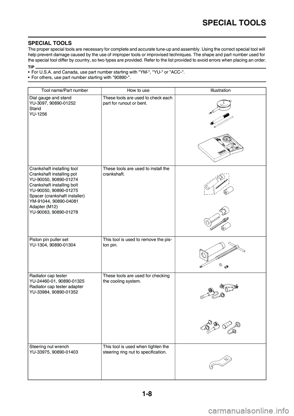
The proper special tools are necessary for complete and accurate tune-up and assembly. Using the correct special tool will
help prevent damage caused by the use of improper tools or improvised techniques. The shape and part number used for
the special tool differ by coun try, so two types are provided. Refer to the list provided to avoid errors when placing an order .
• For U.S.A. and Canada, use part number starting with "YM-", "YU-" or "ACC-".
• For others, use part num ber starting with "90890-".
Tool name/Part number How to use Illustration
Dial gauge and stand
YU-3097, 90890-01252
Stand
YU-1256 These tools are used to check each
part for runout or bent.
Crankshaft installing tool
Crankshaft installing pot
YU-90050, 90890-01274
Crankshaft installing bolt
YU-90050, 90890-01275
Spacer (crankshaft installer)
YM-91044, 90890-04081
Adapter (M12)
YU-90063, 90890-01278 These tools are used to install the
crankshaft.
Piston pin puller set
YU-1304, 90890-01304 This tool is used to remove the pis-
ton pin.
Radiator cap tester
YU-24460-01, 90890-01325
Radiator cap tester adapter
YU-33984, 90890-01352 These tools are used for checking
the cooling system.
Steering nut wrench
YU-33975, 90890-01403 This tool is used when tighten the
steering ring nut to specification.
Page 39 of 230

2-8
MAINTENANCE SPECIFICATIONS
Carburetor: USA, CDN, AUS,
NZ, ZAEUROPE
I. D. mark 5TJE E0 5TJL L0 ----
Main jet (M.J) #162 #160 ----
Main air jet (M.A.J) ø2.0←----
Jet needle (J.N) NFNT NNHU ----
Cutaway (C.A) 1.5←----
Pilot jet (P.J) #45 #48 ----
Pilot air jet (P.A.J) #70←----
Pilot outlet (P.O) ø0.9←----
Bypass (B.P) ø1.0←----
Valve seat size (V.S) ø3.8←----
Starter jet (G.S) #65←----
Leak jet (Acc.P) #60←----
Float height (F.H) 8 mm (0.31 in)←----
Engine idle speed 1,750–1,950 r/min←----
Intake vacuum 34.8–40.1 kPa
(261–301 mmHg,
10.28–11.85 inHg)←----
Hot starter lever free play 3–6 mm (0.12–0.24
in)←----
Lubrication system:
Oil filter type Paper type ----
Oil pump type Trochoid type ----
Tip clearance 0.12 mm or less (0.0047 in or less) 0.20 mm (0.008
in)
Side clearance 0.09–0.17 mm (0.0035–0.0067 in) 0.24 mm (0.009
in)
Housing and rotor clearance 0.03–0.10 mm (0.0012–0.0039 in) 0.17 mm
(0.0067 in)
Bypass valve setting pressure 40–80 kPa (0.4–0.8 kg/cm
2, 5.69–11.38
psi)----
Cooling:
Radiator core size
Width 120.2 mm (4.73 in) ----
Height (Left/Right) 260 mm (10.24 in)/240 mm (9.45 in) ----
Thickness 22 mm (0.87 in) ----
Radiator cap opening pressure 110 kPa (1.1 kg/cm
2, 15.6 psi) ----
Radiator capacity (total) 0.57 L (0.50 Imp qt, 0.60 US qt) ----
Water pump
Type Single-suction centrifugal pump ----Item Standard Limit
Page 61 of 230
3-2
GENERAL MAINTENANCE AND LUBRICATION CHART
(For Canada)
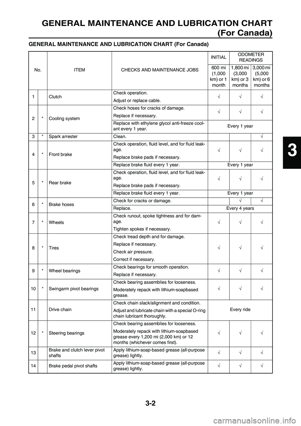
GENERAL MAINTENANCE AND LUBRICATION CHART (For Canada)
No. ITEM CHECKS AND MAINTENANCE JOBSINITIALODOMETER
READINGS600 mi
(1,000
km) or 1
month1,800 mi
(3,000
km) or 3
months3,000 mi
(5,000
km) or 6
months
1 ClutchCheck operation.
√√√
Adjust or replace cable.
2 * Cooling systemCheck hoses for cracks of damage.
√√√
Replace if necessary.
Replace with ethylene glycol anti-freeze cool-
ant every 1 year.Every 1 year
3 * Spark arrester Clean.√
4 * Front brakeCheck operation, fluid level, and for fluid leak-
age.
√√√
Replace brake pads if necessary.
Replace brake fluid every 1 year. Every 1 year
5 * Rear brakeCheck operation, fluid level, and for fluid leak-
age.
√√√
Replace brake pads if necessary.
Replace brake fluid every 1 year. Every 1 year
6 * Brake hosesCheck for cracks or damage.√√
Replace. Every 4 years
7 * WheelsCheck runout, spoke tightness and for dam-
age.
√√√
Tighten spokes if necessary.
8*TiresCheck tread depth and for damage.
√√√ Replace if necessary.
Check air pressure.
Correct if necessary.
9 * Wheel bearingsCheck bearings for smooth operation.
√√√
Replace if necessary.
10 * Swingarm pivot bearingsCheck bearing assemblies for looseness.
√√√
Moderately repack with lithium-soapbased
grease.
11 Drive chainCheck chain slack/alignment and condition.
Every ride
Adjust and lubricate chain with a special O-ring
chain lubricant thoroughly.
12 * Steering bearingsCheck bearing assemblies for looseness.
√√√ Moderately repack with lithium-soapbased
grease every 1,200 mi (2,000 km) or 12
months (whichever comes first).
13Brake and clutch lever pivot
shaftsApply lithium-soap-based grease (all-purpose
grease) lightly.√√√
14 Brake pedal pivot shaftsApply lithium-soap-based grease (all-purpose
grease) lightly.√√√
3
Page 64 of 230
3-5
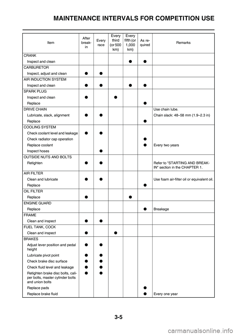
MAINTENANCE INTERVALS FOR COMPETITION USE
CRANK
Inspect and clean●●
CARBURETOR
Inspect, adjust and clean●●
AIR INDUCTION SYSTEM
Inspect and clean●● ●●
SPARK PLUG
Inspect and clean●●
Replace●
DRIVE CHAIN Use chain lube.
Lubricate, slack, alignment●●Chain slack: 48–58 mm (1.9–2.3 in)
Replace●
COOLING SYSTEM
Check coolant level and leakage●●
Check radiator cap operation●
Replace coolant●Every two years
Inspect hoses●
OUTSIDE NUTS AND BOLTS
Retighten●●Refer to "STARTING AND BREAK-
IN" section in the CHAPTER 1.
AIR FILTER
Clean and lubricate●●Use foam air-filter oil or equivalent oil.
Replace●
OIL FILTER
Replace●●
ENGINE GUARD
Replace●Breakage
FRAME
Clean and inspect●●
FUEL TANK, COCK
Clean and inspect●●
BRAKES
Adjust lever position and pedal
height●●
Lubricate pivot point●●
Check brake disc surface●●
Check fluid level and leakage●●
Retighten brake disc bolts, cali-
per bolts, master cylinder bolts
and union bolts●●
Replace pads●
Replace brake fluid●Every one year ItemAfter
break-
inEvery
race
Every
third
(or 500
km)Every
fifth (or
1,000
km)
As re-
quiredRemarks
Page 70 of 230
3-11
ENGINE
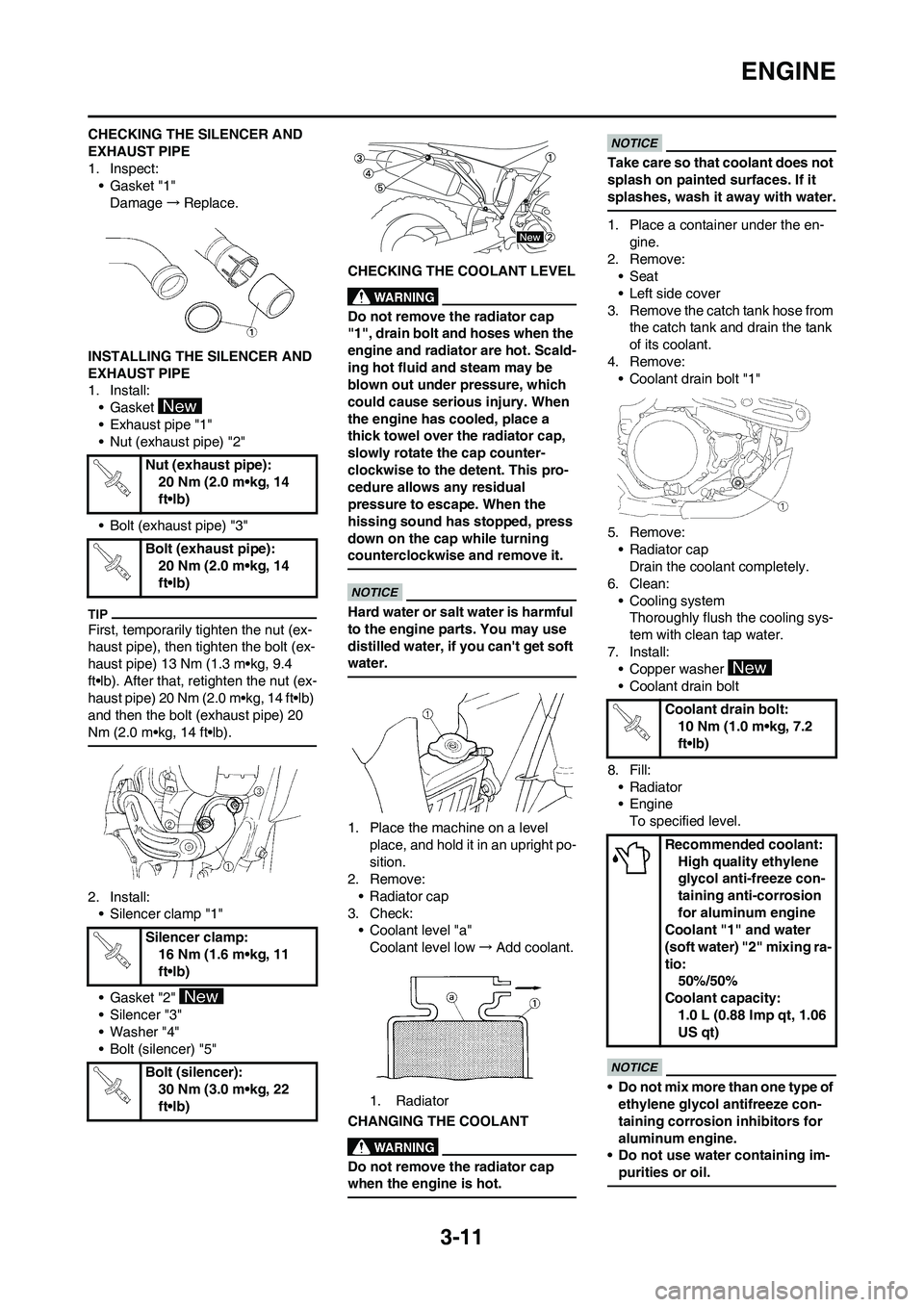
CHECKING THE SILENCER AND
EXHAUST PIPE
1. Inspect:
• Gasket "1"
Damage→Replace.
INSTALLING THE SILENCER AND
EXHAUST PIPE
1. Install:
• Gasket
• Exhaust pipe "1"
• Nut (exhaust pipe) "2"
• Bolt (exhaust pipe) "3"
First, temporarily tighten the nut (ex-
haust pipe), then tighten the bolt (ex-
haust pipe) 13 Nm (1.3 m•kg, 9.4
ft•lb). After that, retighten the nut (ex-
haust pipe) 20 Nm (2.0 m•kg, 14 ft•lb)
and then the bolt (exhaust pipe) 20
Nm (2.0 m•kg, 14 ft•lb).
2. Install:
• Silencer clamp "1"
• Gasket "2"
• Silencer "3"
• Washer "4"
• Bolt (silencer) "5"CHECKING THE COOLANT LEVEL
Do not remove the radiator cap
"1", drain bolt and hoses when the
engine and radiator are hot. Scald-
ing hot fluid and steam may be
blown out under pressure, which
could cause serious injury. When
the engine has cooled, place a
thick towel over the radiator cap,
slowly rotate the cap counter-
clockwise to the detent. This pro-
cedure allows any residual
pressure to escape. When the
hissing sound has stopped, press
down on the cap while turning
counterclockwise and remove it.
Hard water or salt water is harmful
to the engine parts. You may use
distilled water, if you can't get soft
water.
1. Place the machine on a level
place, and hold it in an upright po-
sition.
2. Remove:
• Radiator cap
3. Check:
• Coolant level "a"
Coolant level low→Add coolant.
1. Radiator
CHANGING THE COOLANT
Do not remove the radiator cap
when the engine is hot.
Take care so that coolant does not
splash on painted surfaces. If it
splashes, wash it away with water.
1. Place a container under the en-
gine.
2. Remove:
• Seat
• Left side cover
3. Remove the catch tank hose from
the catch tank and drain the tank
of its coolant.
4. Remove:
• Coolant drain bolt "1"
5. Remove:
• Radiator cap
Drain the coolant completely.
6. Clean:
• Cooling system
Thoroughly flush the cooling sys-
tem with clean tap water.
7. Install:
• Copper washer
• Coolant drain bolt
8. Fill:
•Radiator
• Engine
To specified level.
• Do not mix more than one type of
ethylene glycol antifreeze con-
taining corrosion inhibitors for
aluminum engine.
• Do not use water containing im-
purities or oil.
Nut (exhaust pipe):
20 Nm (2.0 m•kg, 14
ft•lb)
Bolt (exhaust pipe):
20 Nm (2.0 m•kg, 14
ft•lb)
Silencer clamp:
16 Nm (1.6 m•kg, 11
ft•lb)
Bolt (silencer):
30 Nm (3.0 m•kg, 22
ft•lb)
Coolant drain bolt:
10 Nm (1.0 m•kg, 7.2
ft•lb)
Recommended coolant:
High quality ethylene
glycol anti-freeze con-
taining anti-corrosion
for aluminum engine
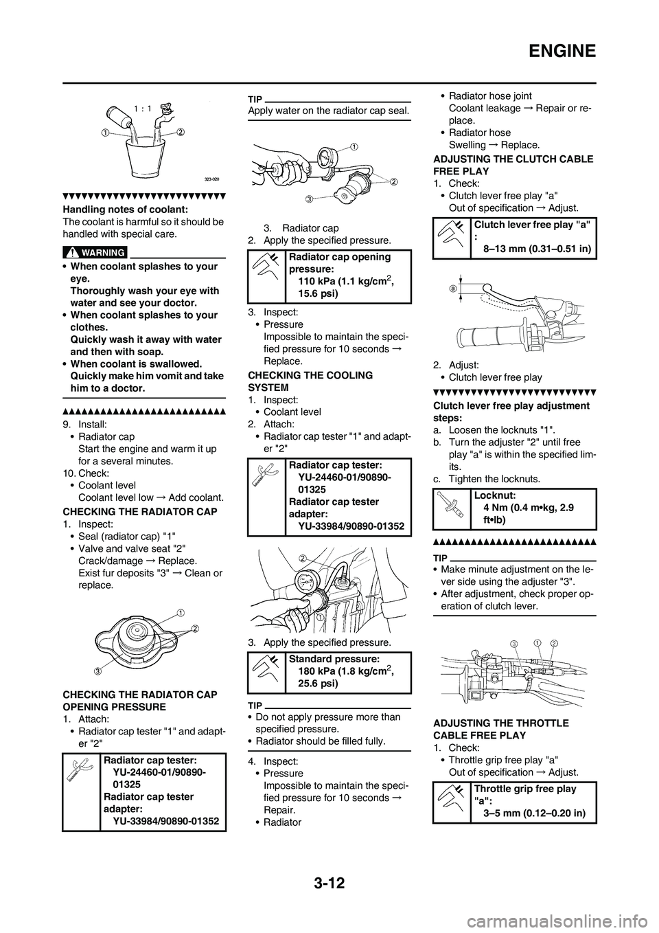
Coolant "1" and water
(soft water) "2" mixing ra-
tio:
50%/50%
Coolant capacity:
1.0 L (0.88 Imp qt, 1.06
US qt)
Page 71 of 230
3-12
ENGINE
Handling notes of coolant:
The coolant is harmful so it should be
handled with special care.
• When coolant splashes to your
eye.
Thoroughly wash your eye with
water and see your doctor.
• When coolant splashes to your
clothes.
Quickly wash it away with water
and then with soap.
• When coolant is swallowed.
Quickly make him vomit and take
him to a doctor.
9. Install:
• Radiator cap
Start the engine and warm it up
for a several minutes.
10. Check:
• Coolant level
Coolant level low→Add coolant.
CHECKING THE RADIATOR CAP
1. Inspect:
• Seal (radiator cap) "1"
• Valve and valve seat "2"
Crack/damage→Replace.
Exist fur deposits "3" →Clean or
replace.
CHECKING THE RADIATOR CAP
OPENING PRESSURE
1. Attach:
• Radiator cap tester "1" and adapt-
er "2"
Apply water on the radiator cap seal.
3. Radiator cap
2. Apply the specified pressure.
3. Inspect:
•Pressure
Impossible to maintain the speci-
fied pressure for 10 seconds→
Replace.
CHECKING THE COOLING
SYSTEM
1. Inspect:
• Coolant level
2. Attach:
• Radiator cap tester "1" and adapt-
er "2"
3. Apply the specified pressure.
• Do not apply pressure more than
specified pressure.
• Radiator should be filled fully.
4. Inspect:
•Pressure
Impossible to maintain the speci-
fied pressure for 10 seconds→
Repair.
• Radiator• Radiator hose joint
Coolant leakage→Repair or re-
place.
• Radiator hose
Swelling→Replace.
ADJUSTING THE CLUTCH CABLE
FREE PLAY
1. Check:
• Clutch lever free play "a"
Out of specification→Adjust.
2. Adjust:
• Clutch lever free play
Clutch lever free play adjustment
steps:
a. Loosen the locknuts "1".
b. Turn the adjuster "2" until free
play "a" is within the specified lim-
its.
c. Tighten the locknuts.
• Make minute adjustment on the le-
ver side using the adjuster "3".
• After adjustment, check proper op-
eration of clutch lever.
ADJUSTING THE THROTTLE
CABLE FREE PLAY
1. Check:
• Throttle grip free play "a"
Out of specification→Adjust. Radiator cap tester:
YU-24460-01/90890-
01325
Radiator cap tester
adapter:
YU-33984/90890-01352
Radiator cap opening
pressure:
110 kPa (1.1 kg/cm
2,
15.6 psi)
Radiator cap tester:
YU-24460-01/90890-
01325
Radiator cap tester
adapter:
YU-33984/90890-01352
Standard pressure:
180 kPa (1.8 kg/cm
2,
25.6 psi)
Clutch lever free play "a"
:
8–13 mm (0.31–0.51 in)
Locknut:
4 Nm (0.4 m•kg, 2.9
ft•lb)
Throttle grip free play
"a":
3–5 mm (0.12–0.20 in)