diagram YAMAHA WR 450F 2010 Owners Manual
[x] Cancel search | Manufacturer: YAMAHA, Model Year: 2010, Model line: WR 450F, Model: YAMAHA WR 450F 2010Pages: 230, PDF Size: 13.87 MB
Page 8 of 230
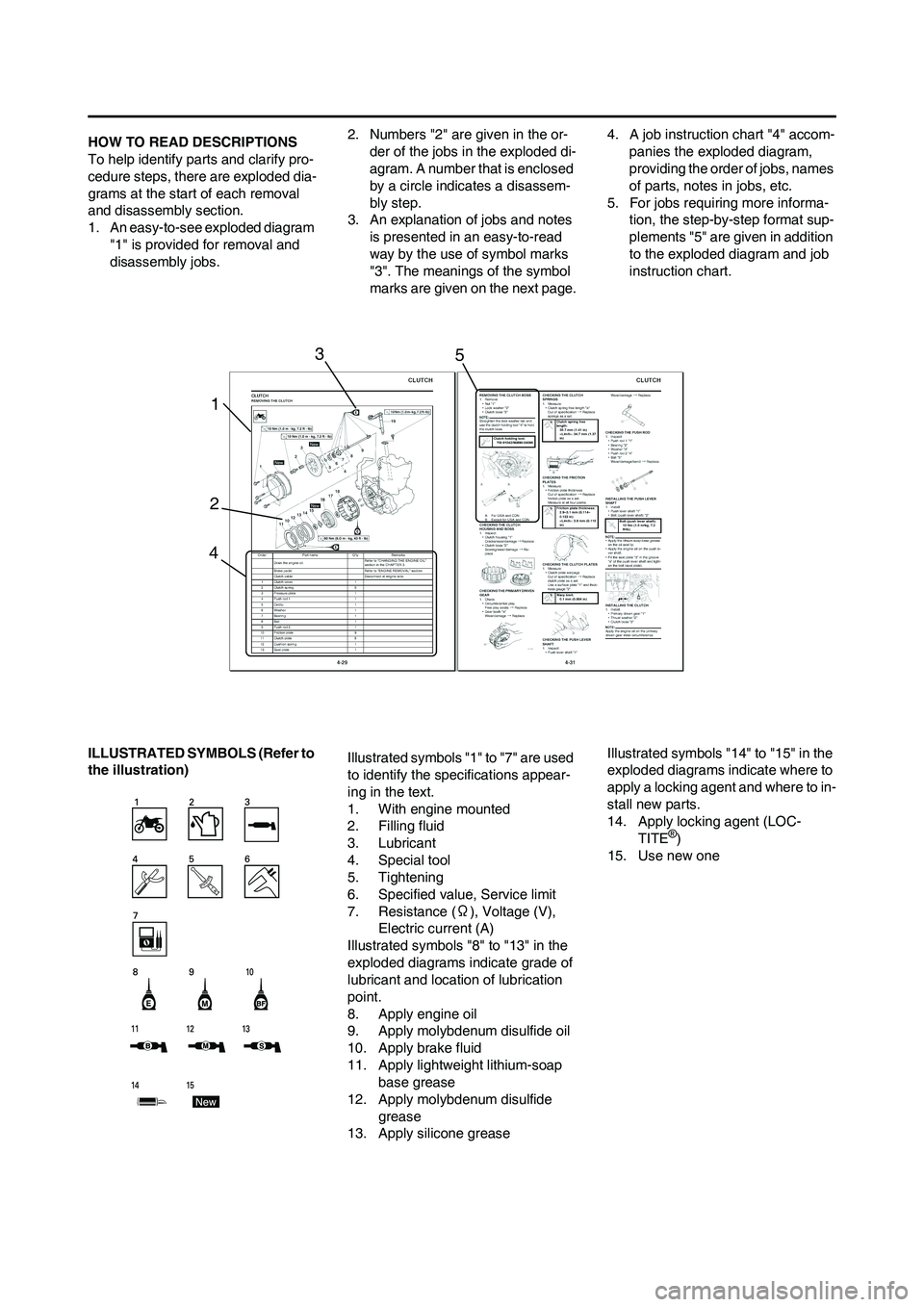
HOW TO READ DESCRIPTIONS
To help identify parts and clarify pro-
cedure steps, there are exploded dia-
grams at the start of each removal
and disassembly section.
1. An easy-to-see exploded diagram "1" is provided for removal and
disassembly jobs. 2. Numbers "2" are given in the or-
der of the jobs in the exploded di-
agram. A number that is enclosed
by a circle indicates a disassem-
bly step.
3. An explanation of jobs and notes is presented in an easy-to-read
way by the use of symbol marks
"3". The meanings of the symbol
marks are given on the next page. 4. A job instruction chart "4" accom-
panies the exploded diagram,
providing the order of jobs, names
of parts, notes in jobs, etc.
5. For jobs requiring more informa- tion, the step-by-step format sup-
plements "5" are given in addition
to the exploded diagram and job
instruction chart.
ILLUSTRATED SYMBO LS (Refer to
the illustration) Illustrated symbols "1" to "7" are used
to identify the specifications appear-
ing in the text.
1. With engine mounted
2. Filling fluid
3. Lubricant
4. Special tool
5. Tightening
6. Specified value, Service limit
7. Resistance (
Ω), Voltage (V),
Electric current (A)
Illustrated symbols "8" to "13" in the
exploded diagrams indicate grade of
lubricant and location of lubrication
point.
8. Apply engine oil
9. Apply molybdenum disulfide oil
10. Apply brake fluid
11. Apply lightweight lithium-soap base grease
12. Apply molybdenum disulfide
grease
13. Apply silicone grease Illustrated symbols "14" to "15" in the
exploded diagrams indicate where to
apply a locking agent and where to in-
stall new parts.
14. Apply locking agent (LOC-
TITE
®)
15. Use new one
1
2 3
4 5
Page 10 of 230
CONTENTS
CHAPTER 1
GENERAL INFOR-
MATION
LOCATION OF
IMPORTANT LABELS ..... 1-1
DESCRIPTION ................. 1-5
CONSUMER
INFORMATION................. 1-6
INCLUDED PARTS .......... 1-6
IMPORTANT
INFORMATION................. 1-6
CHECKING OF
CONNECTION .................. 1-7
SPECIAL TOOLS ............. 1-8
CONTROL
FUNCTIONS ................... 1-12
MULTI-FUNCTION
DISPLAY ........................ 1-13
STARTING AND
BREAK-IN ...................... 1-18
TORQUE-CHECK
POINTS........................... 1-20
CLEANING AND
STORAGE ...................... 1-21
CHAPTER 2
SPECIFICATIONS
GENERAL
SPECIFICATIONS ............ 2-1
MAINTENANCE
SPECIFICATIONS ............ 2-3
TIGHTENING
TORQUES ...................... 2-12
LUBRICATION
DIAGRAMS .................... 2-19
CABLE ROUTING
DIAGRAM ....................... 2-21
CHAPTER 3
REGULAR INSPEC-
TION AND AD-JUSTMENTS
PERIODIC MAINTENANCE
CHART FOR THE EMISSION
CONTROL SYSTEM (For
Canada) ............................ 3-1
GENERAL MAINTENANCE
AND LUBRICATION CHART
(For Canada) .................... 3-2
MAINTENANCE
INTERVALS FOR
COMPETITION USE ......... 3-3
PRE-OPERATION
INSPECTION AND
MAINTENANCE................ 3-7
ENGINE ............................ 3-8
CHASSIS ........................ 3-19
ELECTRICAL ................. 3-29
CHAPTER 4 TUNING
ENGINE
(Except for Canada) ........ 4-1
CHASSIS .......................... 4-5
CHAPTER 5
ENGINE
RADIATOR ....................... 5-1
CARBURETOR................. 5-4
AIR INDICTOIN
SYSTEM ......................... 5-13
CAMSHAFTS.................. 5-15
CYLINDER HEAD........... 5-20
VALVES AND VALVE
SPRINGS ........................ 5-23
CYLINDER AND
PISTON ........................... 5-27
CLUTCH ......................... 5-30 OIL FILTER ELEMENT
AND WATER PUMP .......5-34
BALANCER ....................5-38
OIL PUMP .......................5-40
KICK SHAFT AND SHIFT
SHAFT ............................5-43
AC MAGNETO AND
STARTER CLUTCH........5-48
ENGINE REMOVAL........5-53
CRANKCASE AND
CRANKSHAFT ...............5-57
TRANSMISSION,
SHIFT CAM AND
SHIFT FORK ...................5-63
CHAPTER 6
CHASSIS
FRONT WHEEL AND REAR
WHEEL .............................6-1
FRONT BRAKE AND REAR
BRAKE..............................6-6
FRONT FORK .................6-16
HANDLEBAR..................6-23
STEERING ......................6-27
SWINGARM ....................6-31
REAR SHOCK
ABSORBER ....................6-36
CHAPTER 7
ELECTRICAL
ELECTRICAL
COMPONENTS AND
WIRING DIAGRAM ...........7-1
IGNITION SYSTEM...........7-3
ELECTRIC STARTING
SYSTEM............................7-5
CHARGING SYSTEM .....7-13
THROTTLE POSITION
SENSOR SYSTEM .........7-15
LIGHTING SYSTEM .......7-18
SIGNALING SYSTEM.....7-20
Page 26 of 230
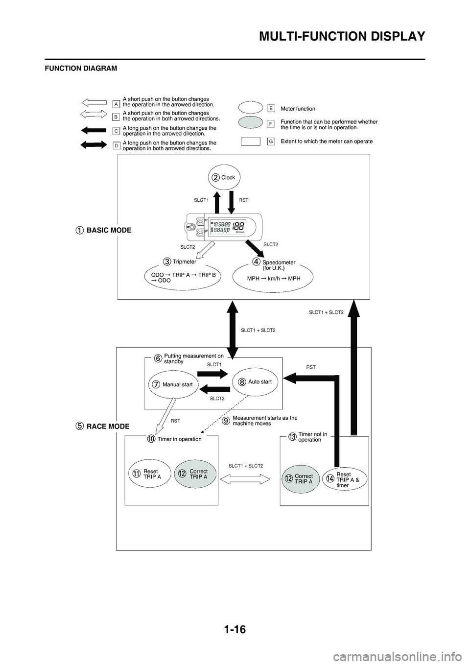
1-16
MULTI-FUNCTION DISPLAY
FUNCTION DIAGRAM
A short push on the button changes
the operation in the arrowed direction.
A short push on the button changes
the operation in both arrowed directions.
A long push on the button changes the
operation in the arrowed direction.
A long push on the button changes the
operation in both arrowed directions.Meter function
Function that can be performed whether
the time is or is not in operation.
Extent to which the meter can operate
Clock
BASIC MODE
Tripmeter
ODO TRIP A TRIP B ODO
Speedometer
(for U.K.)
MPH
km/h MPH
Putting measurement on
standby
Manual startAuto start
RACE MODE
Timer in operation
Reset
TRIP A Correct
TRIP AMeasurement starts as the
machine moves
Timer not in
operation
Correct
TRIP A Reset
TRIP A &
timer
Page 27 of 230
1-17
MULTI-FUNCTION DISPLAY
The following diagram illustrates the
multi-function display regarding the
direction and operation condition in-
volved in each of its functions.
A. A short push on the button changes the operation in the ar-
rowed direction.
B. A short push on the button changes the operation in both
arrowed directions.
C. A long push on the button changes the operation in the ar-
rowed direction.
D. A long push on the button changes the operation in both
arrowed directions.
E. Meter function
F. Function that can be performed whether the time is or is not in
operation.
G. Extent to which the meter can operate 1.
BASIC MODE
2. Clock
3. Trip meter
4. Speedometer (for U.K.)
5. RACE MODE
6. Putting measurement on stand- by
7. Manual start
8. Auto start
9. Measurement starts as the ma- chine moves
10. Timer in operation
11. Reset TRIP A
12. Correct TRIP A
13. Timer not in operation
14. Reset TRIP A & timer
Page 50 of 230
2-19
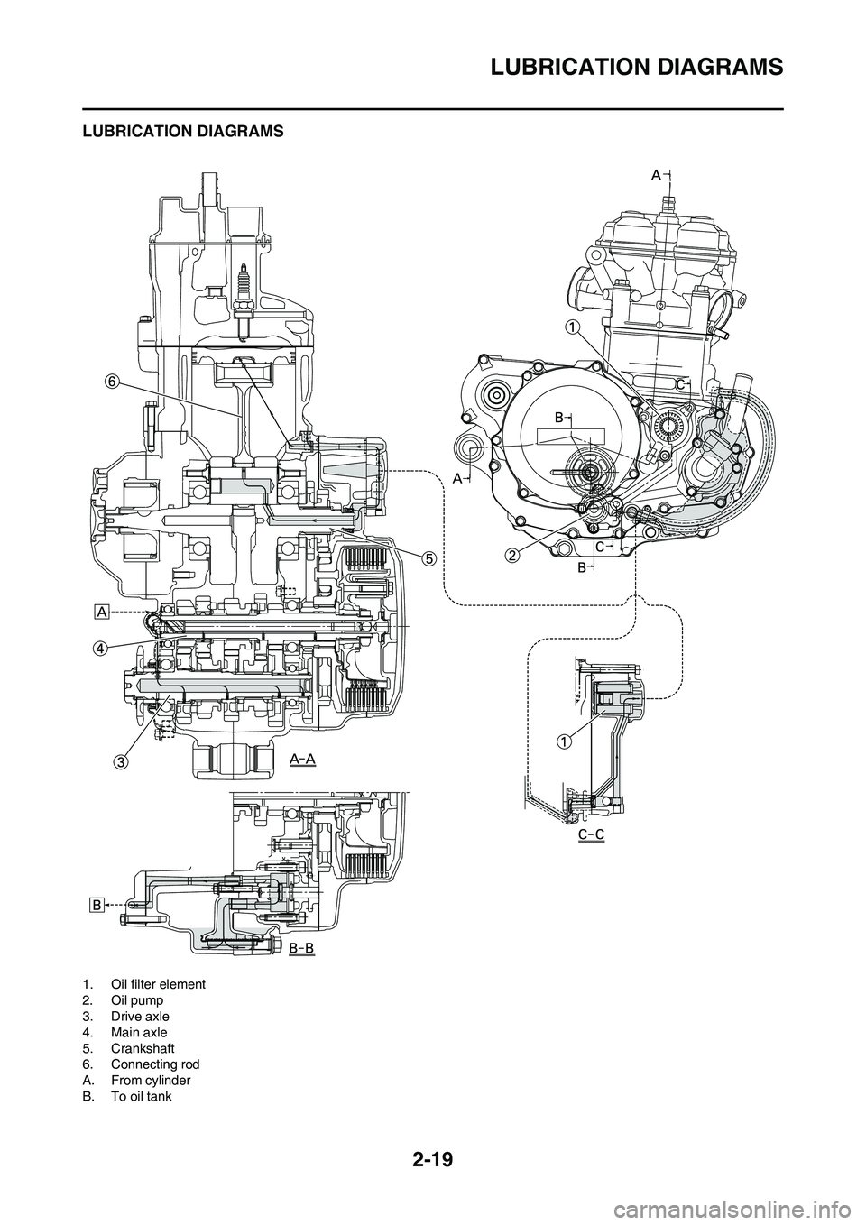
LUBRICATION DIAGRAMS
LUBRICATION DIAGRAMS
1. Oil filter element
2. Oil pump
3. Drive axle
4. Main axle
5. Crankshaft
6. Connecting rod
A. From cylinder
B. To oil tank
Page 51 of 230
2-20
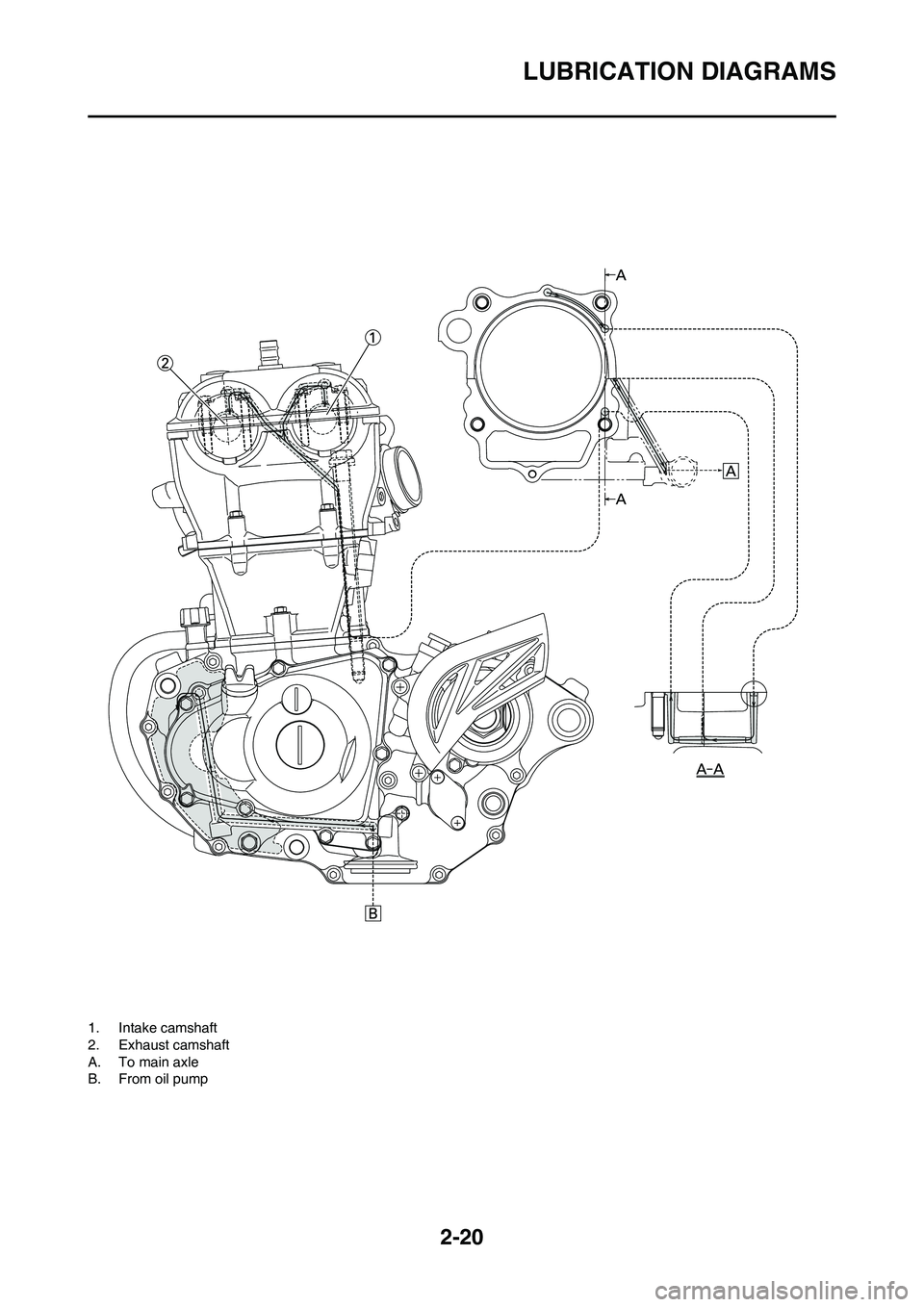
LUBRICATION DIAGRAMS
1. Intake camshaft
2. Exhaust camshaft
A. To main axle
B. From oil pump
Page 52 of 230

2-21
CABLE ROUTING DIAGRAM
CABLE ROUTING DIAGRAM
1. Fuel tank breather hose
2. Clamp
3. Diode
4. Hot starter cable
5. Throttle position sensor lead
6. Wire harness
7. Hump (frame)
8. Negative battery lead
9. Starter motor lead10. Neutral switch lead
11. AC magneto lead
12. Brake hose
13. Rectifier/regulator lead
14. Carburetor breather hose
15. Carburetor overflow hose
16. Catch tank breather hose
17. Hot starter cable protector
18. Rubber cap
Page 53 of 230

2-22
CABLE ROUTING DIAGRAM
A. Insert the end of the fuel tank
breather hose into the hole in
the steering stem.
B. Fasten the throttle cable, hot
starter cable and rectifier/regula-
tor lead onto the frame. Locate
the clamp under the throttle ca-
ble on the right side of the frame,
and face its ends, as well as the
tie ends, downward.
C. Fasten the diode (at the mark-
ing), throttle cable and hot start-
er cable onto the frame. Locate
the clamp end facing toward the
lower right of the frame and with
the tie end facing downward.
D. Fasten the wire harness, throttle
position sensor lead and clutch
cable onto the frame. Pass the
clamp through the hole in the
stay (air cut-off valve). Locate
the clamp end facing toward the
lower side of the frame and cut
off the tie end.
E. Pass the carburetor breather
hoses, carburetor overflow hose
and catch tank breather hose
between the connecting rod and
cross tube (frame).
F. Pass the neutral switch lead on
the inside of the engine bracket.
G. Fasten the neutral switch lead
and AC magneto lead onto the
frame. Locate the clamp end
facing toward the outside of the
frame and tie end facing toward
the rear of the frame.
H. Fasten the AC magneto lead
and neutral switch lead onto the
frame. Locate the clamp end
facing toward the rear of the
frame and cut off the tie end.
I. Pass the neutral switch lead and
AC magneto lead on the inside
of the wire harness.
J. Fasten the AC magneto lead
and neutral switch lead onto the
frame.
K. Pass the wire harness through
the cable guide.
L. Locate the couplers in the frame
recess.
M. Pass the carburetor breather
hoses, carburetor overflow hose
and catch tank breather hose so
that the hoses do not contact the
rear shock absorber.
N. Secure the coupler by pushing it
into the hole in the headlight
unit.
O. Fasten the throttle position sen-
sor lead and the hot starter ca-
ble.P. Locate the clamp between the
hot starter cable protector and
rubber cap.
Page 54 of 230
2-23
CABLE ROUTING DIAGRAM
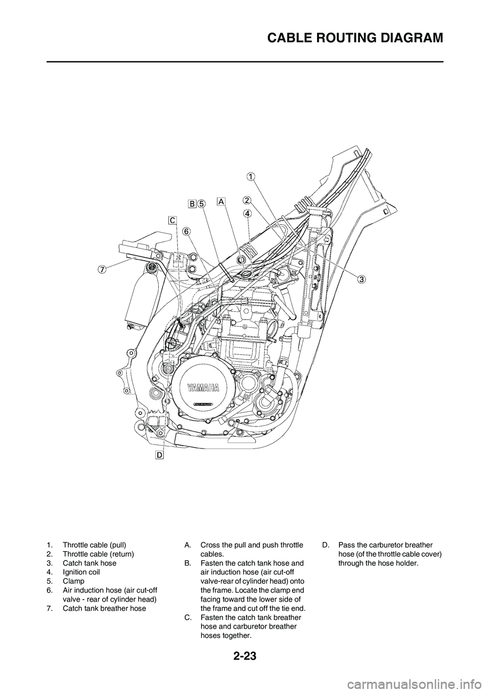
1. Throttle cable (pull)
2. Throttle cable (return)
3. Catch tank hose
4. Ignition coil
5. Clamp
6. Air induction hose (air cut-off
valve - rear of cylinder head)
7. Catch tank breather hoseA. Cross the pull and push throttle
cables.
B. Fasten the catch tank hose and
air induction hose (air cut-off
valve-rear of cylinder head) onto
the frame. Locate the clamp end
facing toward the lower side of
the frame and cut off the tie end.
C. Fasten the catch tank breather
hose and carburetor breather
hoses together.D. Pass the carburetor breather
hose (of the throttle cable cover)
through the hose holder.
Page 55 of 230
2-24
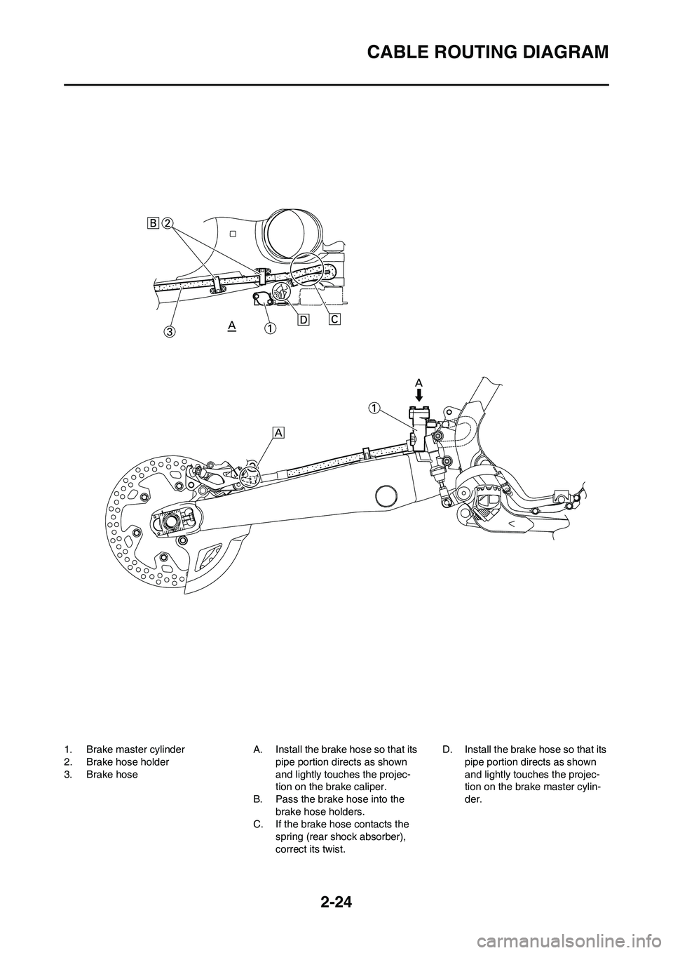
CABLE ROUTING DIAGRAM
1. Brake master cylinder
2. Brake hose holder
3. Brake hoseA. Install the brake hose so that its
pipe portion directs as shown
and lightly touches the projec-
tion on the brake caliper.
B. Pass the brake hose into the
brake hose holders.
C. If the brake hose contacts the
spring (rear shock absorber),
correct its twist.D. Install the brake hose so that its
pipe portion directs as shown
and lightly touches the projec-
tion on the brake master cylin-
der.