fuel tank removal YAMAHA WR 450F 2010 Owners Manual
[x] Cancel search | Manufacturer: YAMAHA, Model Year: 2010, Model line: WR 450F, Model: YAMAHA WR 450F 2010Pages: 230, PDF Size: 13.87 MB
Page 16 of 230
1-6
CONSUMER INFORMATION
CONSUMER INFORMATION
There are two significant reasons for
knowing the serial number of your
machine:
1. When ordering parts, you can give the number to your Yamaha
dealer for positive identification of
the model you own.
2. If your machine is stolen, the au-
thorities will need the number to
search for and identify your ma-
chine.
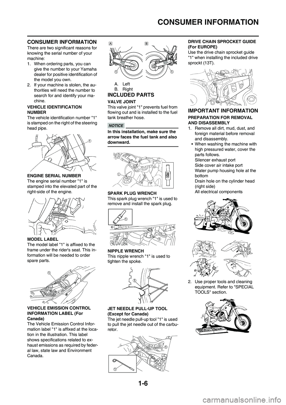
VEHICLE IDENTIFICATION
NUMBER
The vehicle identification number "1"
is stamped on the ri ght of the steering
head pipe.
ENGINE SERIAL NUMBER
The engine serial number "1" is
stamped into the elevated part of the
right-side of the engine.
MODEL LABEL
The model label "1" is affixed to the
frame under the rider's seat. This in-
formation will be needed to order
spare parts.
VEHICLE EMISSION CONTROL
INFORMATION LABEL (For
Canada)
The Vehicle Emission Control Infor-
mation label "1" is affixed at the loca-
tion in the illustration. This label
shows specifications related to ex-
haust emissions as required by feder-
al law, state law and Environment
Canada. A. Left
B. Right
INCLUDED PARTS
VALVE JOINT
This valve joint "1" prevents fuel from
flowing out and is installed to the fuel
tank breather hose.
In this installation, make sure the
arrow faces the fuel tank and also
downward.
SPARK PLUG WRENCH
This spark plug wrench "1" is used to
remove and install the spark plug.
NIPPLE WRENCH
This nipple wrench "1" is used to
tighten the spoke.
JET NEEDLE PULL-UP TOOL
(Except for Canada)
The jet needle pull-up tool "1" is used
to pull the jet needle out of the carbu-
retor.DRIVE CHAIN SPROCKET GUIDE
(For EUROPE)
Use the drive chain sprocket guide
"1" when installing the included drive
sprockt (13T).
IMPORTANT INFORMATION
PREPARATION FOR REMOVAL
AND DISASSEMBLY
1. Remove all dirt, mud, dust, and
foreign material before removal
and disassembly.
• When washing the machine with
high pressured water, cover the
parts follows.
Silencer exhaust port
Side cover air intake port
Water pump housing hole at the
bottom
Drain hole on the cylinder head
(right side)
All electrical components
2. Use proper tools and cleaning equipment. Refer to "SPECIAL
TOOLS" section.
Page 67 of 230
3-8
ENGINE
ENGINE
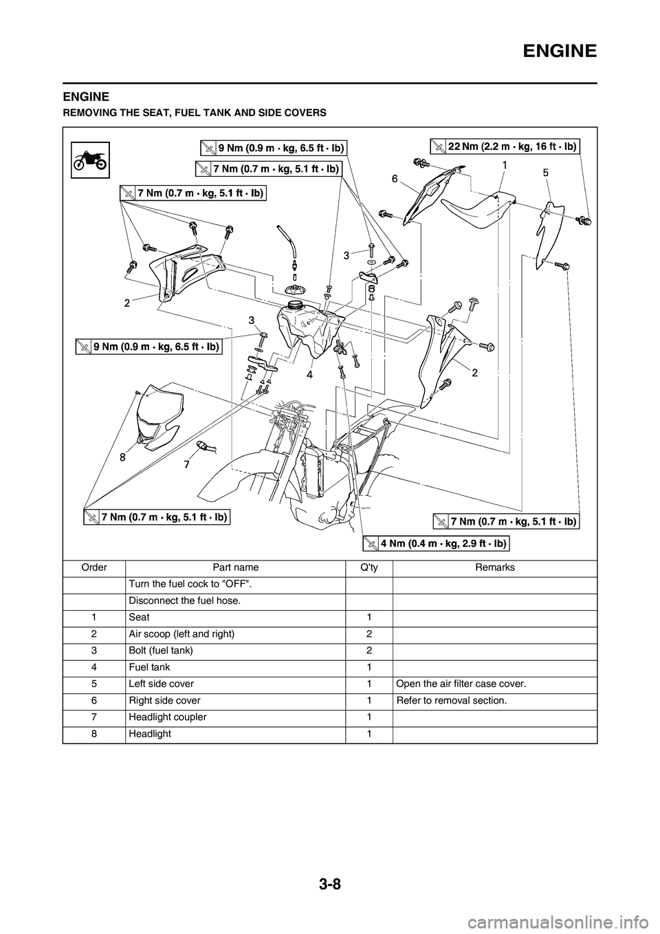
REMOVING THE SEAT, FUEL TANK AND SIDE COVERS
Order Part name Q'ty Remarks
Turn the fuel cock to "OFF".
Disconnect the fuel hose.
1Seat 1
2 Air scoop (left and right) 2
3 Bolt (fuel tank) 2
4 Fuel tank 1
5 Left side cover 1 Open the air filter case cover.
6 Right side cover 1 Refer to removal section.
7 Headlight coupler 1
8 Headlight 1
Page 118 of 230
5-15
CAMSHAFTS
CAMSHAFTS
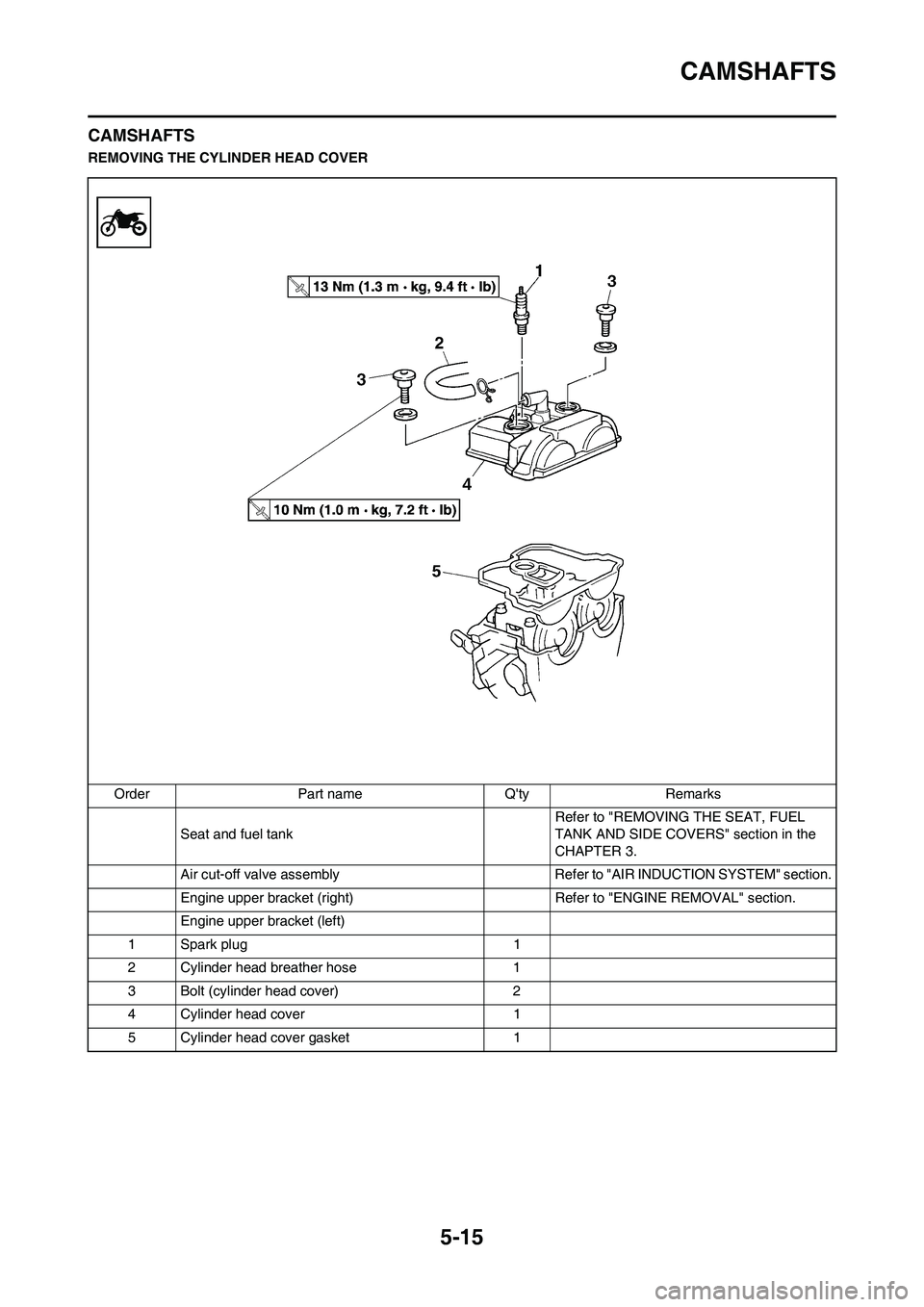
REMOVING THE CYLINDER HEAD COVER
Order Part name Q'ty Remarks
Seat and fuel tank Refer to "REMOVING THE SEAT, FUEL
TANK AND SIDE COVERS" section in the
CHAPTER 3.
Air cut-off valve assembly Refer to "AIR INDUCTION SYSTEM" section.
Engine upper bracket (right) Refer to "ENGINE REMOVAL" section.
Engine upper bracket (left)
1 Spark plug 1
2 Cylinder head breather hose 1
3 Bolt (cylinder head cover) 2
4 Cylinder head cover 1
5 Cylinder head cover gasket 1
Page 151 of 230
5-48
AC MAGNETO AND STARTER CLUTCH
AC MAGNETO AND STARTER CLUTCH
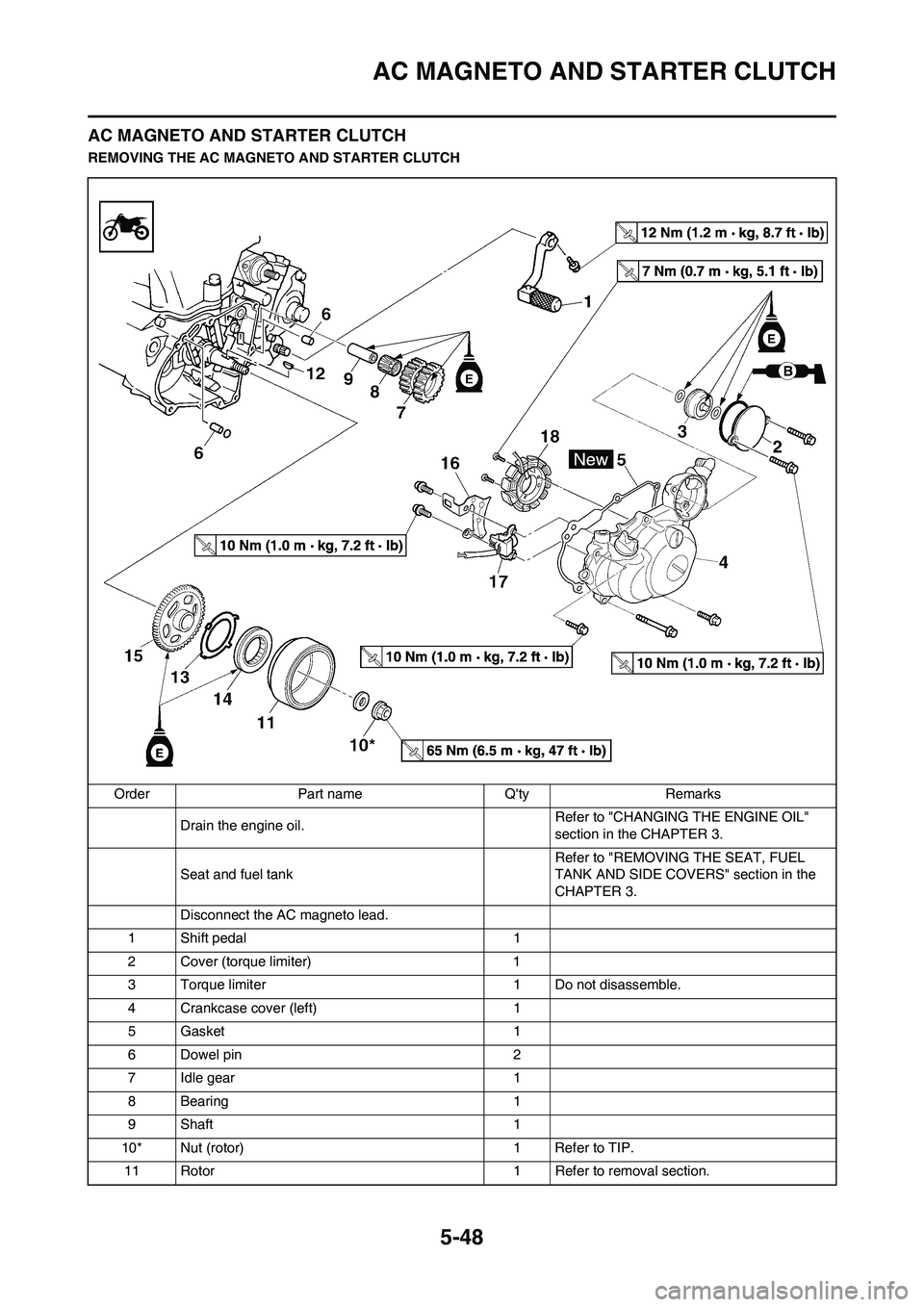
REMOVING THE AC MAGNETO AND STARTER CLUTCH
Order Part name Q'ty Remarks
Drain the engine oil.Refer to "CHANGING THE ENGINE OIL"
section in the CHAPTER 3.
Seat and fuel tankRefer to "REMOVING THE SEAT, FUEL
TANK AND SIDE COVERS" section in the
CHAPTER 3.
Disconnect the AC magneto lead.
1 Shift pedal 1
2 Cover (torque limiter) 1
3 Torque limiter 1 Do not disassemble.
4 Crankcase cover (left) 1
5 Gasket 1
6 Dowel pin 2
7 Idle gear 1
8 Bearing 1
9Shaft 1
10* Nut (rotor) 1 Refer to TIP.
11 Rotor 1 Refer to removal section.
Page 156 of 230
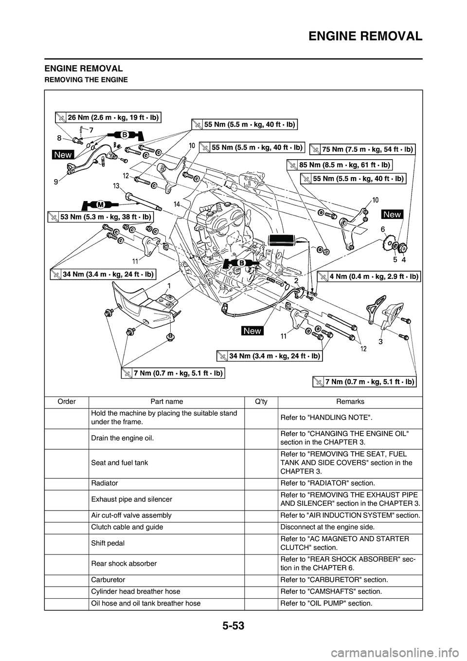
5-53
ENGINE REMOVAL
ENGINE REMOVAL
REMOVING THE ENGINE
Order Part name Q'ty Remarks
Hold the machine by placing the suitable stand
under the frame.Refer to "HANDLING NOTE".
Drain the engine oil.Refer to "CHANGING THE ENGINE OIL"
section in the CHAPTER 3.
Seat and fuel tank Refer to "REMOVING THE SEAT, FUEL
TANK AND SIDE COVERS" section in the
CHAPTER 3.
Radiator Refer to "RADIATOR" section.
Exhaust pipe and silencer Refer to "REMOVING THE EXHAUST PIPE
AND SILENCER" section in the CHAPTER 3.
Air cut-off valve assembly Refer to "AIR INDUCTION SYSTEM" section.
Clutch cable and guide Disconnect at the engine side.
Shift pedalRefer to "AC MAGNETO AND STARTER
CLUTCH" section.
Rear shock absorberRefer to "REAR SHOCK ABSORBER" sec-
tion in the CHAPTER 6.
Carburetor Refer to "CARBURETOR" section.
Cylinder head breather hose Refer to "CAMSHAFTS" section.
Oil hose and oil tank breather hose Refer to "OIL PUMP" section.