oil capacity YAMAHA WR 450F 2010 Owners Manual
[x] Cancel search | Manufacturer: YAMAHA, Model Year: 2010, Model line: WR 450F, Model: YAMAHA WR 450F 2010Pages: 230, PDF Size: 13.87 MB
Page 32 of 230
2-1
GENERAL SPECIFICATIONS
SPECIFICATIONS
GENERAL SPECIFICATIONS
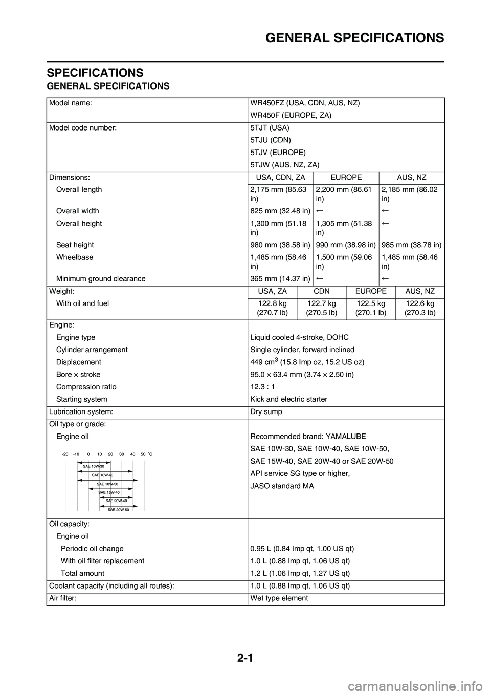
Model name: WR450FZ (USA, CDN, AUS, NZ)WR450F (EUROPE, ZA)
Model code number: 5TJT (USA) 5TJU (CDN)
5TJV (EUROPE)
5TJW (AUS, NZ, ZA)
Dimensions: USA, CDN, ZA EUROPE AUS, NZ
Overall length 2,175 mm (85.63 in)2,200 mm (86.61
in)2,185 mm (86.02
in)
Overall width 825 mm (32.48 in) ←←
Overall height 1,300 mm (51.18 in)1,305 mm (51.38
in)←
Seat height 980 mm (38.58 in) 990 mm (38.98 in) 985 mm (38.78 in)
Wheelbase 1,485 mm (58.46 in)1,500 mm (59.06
in)1,485 mm (58.46
in)
Minimum ground clearance 365 mm (14.37 in) ←←
Weight: USA, ZA CDN EUROPE AUS, NZ With oil and fuel 122.8 kg (270.7 lb)122.7 kg
(270.5 lb) 122.5 kg
(270.1 lb) 122.6 kg
(270.3 lb)
Engine: Engine type Liquid cooled 4-stroke, DOHC
Cylinder arrangement Single cylinder, forward inclined
Displacement 449 cm
3 (15.8 Imp oz, 15.2 US oz)
Bore × stroke 95.0 × 63.4 mm (3.74 × 2.50 in)
Compression ratio 12.3 : 1
Starting system Kick and electric starter
Lubrication system: Dry sump
Oil type or grade: Engine oil Recommended brand: YAMALUBE SAE 10W-30, SAE 10W-40, SAE 10W-50,
SAE 15W-40, SAE 20W-40 or SAE 20W-50
API service SG type or higher,
JASO standard MA
Oil capacity: Engine oilPeriodic oil change 0.95 L (0.84 Imp qt, 1.00 US qt)
With oil filter replacement 1.0 L (0.88 Imp qt, 1.06 US qt)
Total amount 1.2 L (1.06 Imp qt, 1.27 US qt)
Coolant capacity (including all routes): 1.0 L (0.88 Imp qt, 1.06 US qt)
Air filter: Wet type element
Page 34 of 230
2-3
MAINTENANCE SPECIFICATIONS
MAINTENANCE SPECIFICATIONS
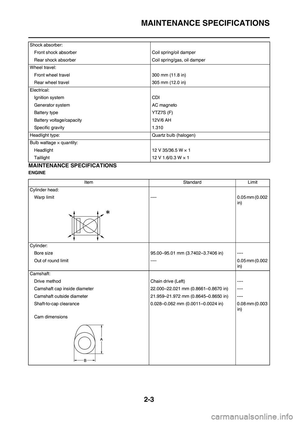
ENGINEShock absorber:
Front shock absorber Coil spring/oil damper
Rear shock absorber Coil spring/gas, oil damper
Wheel travel:
Front wheel travel 300 mm (11.8 in)
Rear wheel travel 305 mm (12.0 in)
Electrical:
Ignition system CDI
Generator system AC magneto
Battery type YTZ7S (F)
Battery voltage/capacity 12V/6 AH
Specific gravity 1.310
Headlight type: Quartz bulb (halogen)
Bulb wattage × quantity:
Headlight 12 V 35/36.5 W × 1
Taillight 12 V 1.6/0.3 W × 1
Item Standard Limit
Cylinder head:
Warp limit ---- 0.05 mm (0.002
in)
Cylinder:
Bore size 95.00–95.01 mm (3.7402–3.7406 in) ----
Out of round limit ---- 0.05 mm (0.002
in)
Camshaft:
Drive method Chain drive (Left) ----
Camshaft cap inside diameter 22.000–22.021 mm (0.8661–0.8670 in) ----
Camshaft outside diameter 21.959–21.972 mm (0.8645–0.8650 in) ----
Shaft-to-cap clearance 0.028–0.062 mm (0.0011–0.0024 in) 0.08 mm (0.003
in)
Cam dimensions
Page 39 of 230

2-8
MAINTENANCE SPECIFICATIONS
Carburetor: USA, CDN, AUS,
NZ, ZAEUROPE
I. D. mark 5TJE E0 5TJL L0 ----
Main jet (M.J) #162 #160 ----
Main air jet (M.A.J) ø2.0←----
Jet needle (J.N) NFNT NNHU ----
Cutaway (C.A) 1.5←----
Pilot jet (P.J) #45 #48 ----
Pilot air jet (P.A.J) #70←----
Pilot outlet (P.O) ø0.9←----
Bypass (B.P) ø1.0←----
Valve seat size (V.S) ø3.8←----
Starter jet (G.S) #65←----
Leak jet (Acc.P) #60←----
Float height (F.H) 8 mm (0.31 in)←----
Engine idle speed 1,750–1,950 r/min←----
Intake vacuum 34.8–40.1 kPa
(261–301 mmHg,
10.28–11.85 inHg)←----
Hot starter lever free play 3–6 mm (0.12–0.24
in)←----
Lubrication system:
Oil filter type Paper type ----
Oil pump type Trochoid type ----
Tip clearance 0.12 mm or less (0.0047 in or less) 0.20 mm (0.008
in)
Side clearance 0.09–0.17 mm (0.0035–0.0067 in) 0.24 mm (0.009
in)
Housing and rotor clearance 0.03–0.10 mm (0.0012–0.0039 in) 0.17 mm
(0.0067 in)
Bypass valve setting pressure 40–80 kPa (0.4–0.8 kg/cm
2, 5.69–11.38
psi)----
Cooling:
Radiator core size
Width 120.2 mm (4.73 in) ----
Height (Left/Right) 260 mm (10.24 in)/240 mm (9.45 in) ----
Thickness 22 mm (0.87 in) ----
Radiator cap opening pressure 110 kPa (1.1 kg/cm
2, 15.6 psi) ----
Radiator capacity (total) 0.57 L (0.50 Imp qt, 0.60 US qt) ----
Water pump
Type Single-suction centrifugal pump ----Item Standard Limit
Page 40 of 230
2-9
MAINTENANCE SPECIFICATIONS
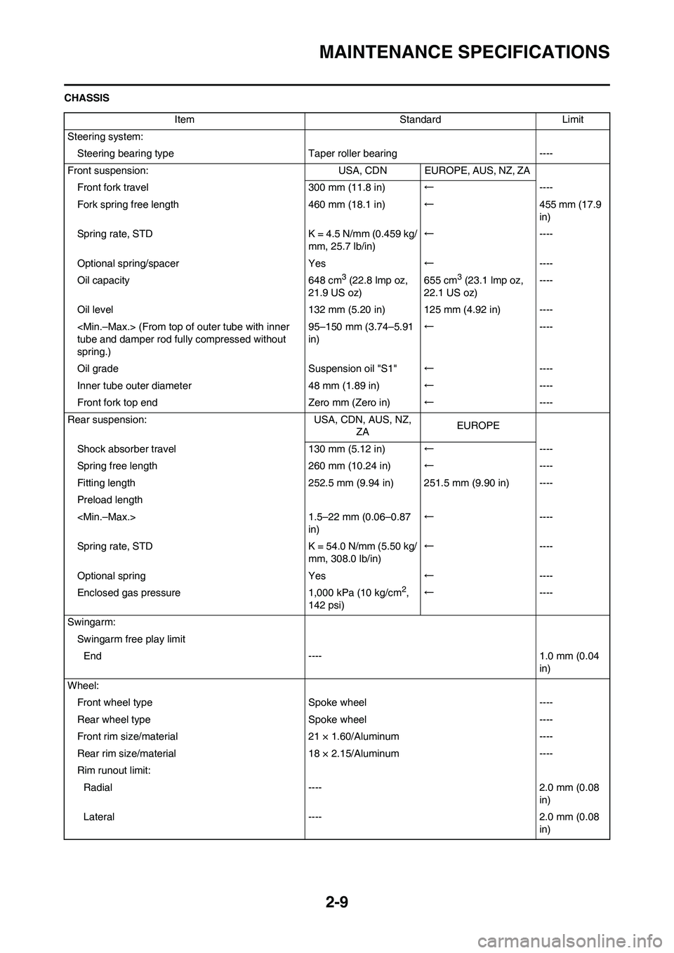
CHASSIS
Item Standard Limit
Steering system:
Steering bearing typeTaper roller bearing ----
Front suspension: USA, CDN EUROPE, AUS, NZ, ZA
Front fork travel 300 mm (11.8 in)←----
Fork spring free length 460 mm (18.1 in)←455 mm (17.9
in)
Spring rate, STD K = 4.5 N/mm (0.459 kg/
mm, 25.7 lb/in)←----
Optional spring/spacer Yes←----
Oil capacity 648 cm
3 (22.8 lmp oz,
21.9 US oz)655 cm3 (23.1 lmp oz,
22.1 US oz)----
Oil level 132 mm (5.20 in) 125 mm (4.92 in) ----
tube and damper rod fully compressed without
spring.)95–150 mm (3.74–5.91
in)←----
Oil grade Suspension oil "S1"←----
Inner tube outer diameter 48 mm (1.89 in)←----
Front fork top end Zero mm (Zero in)←----
Rear suspension: USA, CDN, AUS, NZ,
ZAEUROPE
Shock absorber travel 130 mm (5.12 in)←----
Spring free length 260 mm (10.24 in)←----
Fitting length 252.5 mm (9.94 in) 251.5 mm (9.90 in) ----
Preload length
in)←----
Spring rate, STD K = 54.0 N/mm (5.50 kg/
mm, 308.0 lb/in)←----
Optional spring Yes←----
Enclosed gas pressure 1,000 kPa (10 kg/cm
2,
142 psi)←----
Swingarm:
Swingarm free play limit
End ---- 1.0 mm (0.04
in)
Wheel:
Front wheel type Spoke wheel ----
Rear wheel typeSpoke wheel ----
Front rim size/material 21 × 1.60/Aluminum ----
Rear rim size/material 18 × 2.15/Aluminum ----
Rim runout limit:
Radial ---- 2.0 mm (0.08
in)
Lateral ---- 2.0 mm (0.08
in)
Page 42 of 230
2-11
MAINTENANCE SPECIFICATIONS
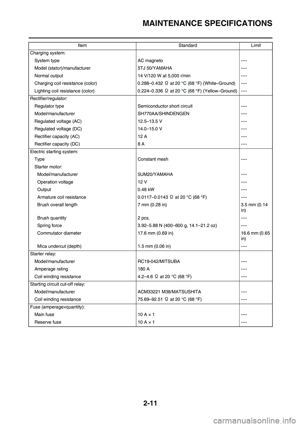
Charging system:
System type AC magneto ----
Model (stator)/manufacturer 5TJ 50/YAMAHA ----
Normal output 14 V/120 W at 5,000 r/min ----
Charging coil resistance (color) 0.288–0.432 Ω at 20 °C (68 °F) (White–Ground) ----
Lighting coil resistance (color) 0.224–0.336 Ω at 20 °C (68 °F) (Yellow–Ground) ----
Rectifier/regulator:
Regulator type Semiconductor short circuit ----
Model/manufacturer SH770AA/SHINDENGEN ----
Regulated voltage (AC) 12.5–13.5 V ----
Regulated voltage (DC) 14.0–15.0 V ----
Rectifier capacity (AC) 12 A ----
Rectifier capacity (DC) 8 A ----
Electric starting system:
Type Constant mesh ----
Starter motor:
Model/manufacturer 5UM20/YAMAHA ----
Operation voltage 12 V ----
Output 0.48 kW ----
Armature coil resistance 0.0117–0.0143 Ω at 20 °C (68 °F) ----
Brush overall length 7 mm (0.28 in) 3.5 mm (0.14
in)
Brush quantity 2 pcs. ----
Spring force 3.92–5.88 N (400–600 g, 14.1–21.2 oz) ----
Commutator diameter 17.6 mm (0.69 in) 16.6 mm (0.65
in)
Mica undercut (depth) 1.5 mm (0.06 in) ----
Starter relay:
Model/manufacturerRC19-042/MITSUBA ----
Amperage rating 180 A ----
Coil winding resistance 4.2–4.6 Ω at 20 °C (68 °F) ----
Starting circuit cut-off relay:
Model/manufacturer ACM33221 M38/MATSUSHITA ----
Coil winding resistance 75.69–92.51 Ω at 20 °C (68 °F) ----
Fuse (amperage×quantity):
Main fuse 10 A × 1 ----
Reserve fuse 10 A × 1 ----Item Standard Limit
Page 70 of 230
3-11
ENGINE
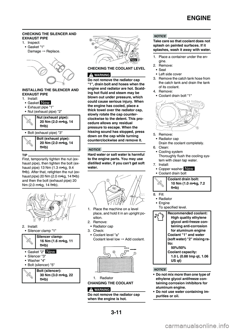
CHECKING THE SILENCER AND
EXHAUST PIPE
1. Inspect:
• Gasket "1"
Damage→Replace.
INSTALLING THE SILENCER AND
EXHAUST PIPE
1. Install:
• Gasket
• Exhaust pipe "1"
• Nut (exhaust pipe) "2"
• Bolt (exhaust pipe) "3"
First, temporarily tighten the nut (ex-
haust pipe), then tighten the bolt (ex-
haust pipe) 13 Nm (1.3 m•kg, 9.4
ft•lb). After that, retighten the nut (ex-
haust pipe) 20 Nm (2.0 m•kg, 14 ft•lb)
and then the bolt (exhaust pipe) 20
Nm (2.0 m•kg, 14 ft•lb).
2. Install:
• Silencer clamp "1"
• Gasket "2"
• Silencer "3"
• Washer "4"
• Bolt (silencer) "5"CHECKING THE COOLANT LEVEL
Do not remove the radiator cap
"1", drain bolt and hoses when the
engine and radiator are hot. Scald-
ing hot fluid and steam may be
blown out under pressure, which
could cause serious injury. When
the engine has cooled, place a
thick towel over the radiator cap,
slowly rotate the cap counter-
clockwise to the detent. This pro-
cedure allows any residual
pressure to escape. When the
hissing sound has stopped, press
down on the cap while turning
counterclockwise and remove it.
Hard water or salt water is harmful
to the engine parts. You may use
distilled water, if you can't get soft
water.
1. Place the machine on a level
place, and hold it in an upright po-
sition.
2. Remove:
• Radiator cap
3. Check:
• Coolant level "a"
Coolant level low→Add coolant.
1. Radiator
CHANGING THE COOLANT
Do not remove the radiator cap
when the engine is hot.
Take care so that coolant does not
splash on painted surfaces. If it
splashes, wash it away with water.
1. Place a container under the en-
gine.
2. Remove:
• Seat
• Left side cover
3. Remove the catch tank hose from
the catch tank and drain the tank
of its coolant.
4. Remove:
• Coolant drain bolt "1"
5. Remove:
• Radiator cap
Drain the coolant completely.
6. Clean:
• Cooling system
Thoroughly flush the cooling sys-
tem with clean tap water.
7. Install:
• Copper washer
• Coolant drain bolt
8. Fill:
•Radiator
• Engine
To specified level.
• Do not mix more than one type of
ethylene glycol antifreeze con-
taining corrosion inhibitors for
aluminum engine.
• Do not use water containing im-
purities or oil.
Nut (exhaust pipe):
20 Nm (2.0 m•kg, 14
ft•lb)
Bolt (exhaust pipe):
20 Nm (2.0 m•kg, 14
ft•lb)
Silencer clamp:
16 Nm (1.6 m•kg, 11
ft•lb)
Bolt (silencer):
30 Nm (3.0 m•kg, 22
ft•lb)
Coolant drain bolt:
10 Nm (1.0 m•kg, 7.2
ft•lb)
Recommended coolant:
High quality ethylene
glycol anti-freeze con-
taining anti-corrosion
for aluminum engine
Coolant "1" and water
(soft water) "2" mixing ra-
tio:
50%/50%
Coolant capacity:
1.0 L (0.88 Imp qt, 1.06
US qt)
Page 227 of 230

7-19
LIGHTING SYSTEM
CHECKING THE TAILLIGHT
(LEDs)
1. Disconnect the taillight coupler.
2. Connect two jumper leads "1"
from the battery terminals to the
respective coupler terminal as
shown.
3. Check:
• LED (for proper operation)
Does not light→Replace the tail-
light assembly.
• A wire that is used as a jumper
lead must have at least the same
capacity of the battery lead, oth-
erwise the jumper lead may burn.
• This check is likely to produce
sparks, therefore, make sure no
flammable gas or fluid is in the
vicinity.
CHECKING THE AC MAGNETO
1. Inspect:
• Lighting coil resistance
Out of specification→Replace.CHECKING THE RECTIFIER/
REGULATOR
1. Connect the battery leads.
2. Start the engine.
3. Turn on the headlight and taillight
by turning on the light switch.
4. Inspect:
• Out-put voltage
Out of specification→Replace
rectifier/regulator. Battery (+) terminal→Blue lead
"2"
Battery (-) terminal→Black lead
"3"
Tester (+) lead→Yellow lead "1"
Tester (-) lead→Ground "2"
Light-
ing coil
resis-
tanceTester selector
position
0.224–
0.336 Ω
at 20 °C
(68 °F) Ω × 1
Tester (+) lead→Yellow lead "1"
Tester (-) lead→Black lead "2"
Out-put
voltageTester se-
lector posi-
tion
12.5–13.5 V
at 5,000 r/
minACV-20