service YAMAHA WR 450F 2012 Owners Manual
[x] Cancel search | Manufacturer: YAMAHA, Model Year: 2012, Model line: WR 450F, Model: YAMAHA WR 450F 2012Pages: 96, PDF Size: 2.47 MB
Page 31 of 96
INSTRUMENT AND CONTROL FUNCTIONS
3-16
234
5
6
7
8
9
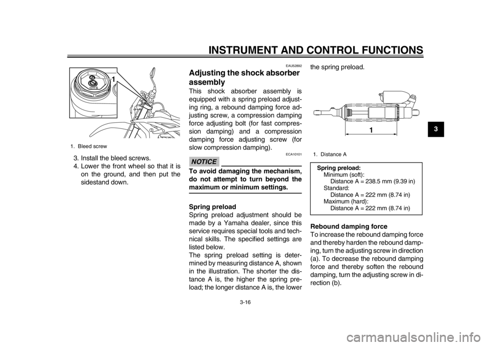
3. Install the bleed screws.
4. Lower the front wheel so that it is
on the ground, and then put the
sidestand down.
EAU52892
Adjusting the shock absorber
assembly This shock absorber assembly is
equipped with a spring preload adjust-
ing ring, a rebound damping force ad-
justing screw, a compression damping
force adjusting bolt (for fast compres-
sion damping) and a compression
damping force adjusting screw (for
slow compression damping).NOTICE
ECA10101
To avoid damaging the mechanism,
do not attempt to turn beyond themaximum or minimum settings.
Spring preload
Spring preload adjustment should be
made by a Yamaha dealer, since this
service requires special tools and tech-
nical skills. The specified settings are
listed below.
The spring preload setting is deter-
mined by measuring distance A, shown
in the illustration. The shorter the dis-
tance A is, the higher the spring pre-
load; the longer distance A is, the lower the spring preload.
Rebound damping force
To increase the rebound damping force
and thereby harden the rebound damp-
ing, turn the adjusting screw in direction
(a). To decrease the rebound damping
force and thereby soften the rebound
damping, turn the adjusting screw in di-
rection (b).
1. Bleed screw
1
1. Distance ASpring preload:
Minimum (soft):
Distance A = 238.5 mm (9.39 in)
Standard: Distance A = 222 mm (8.74 in)
Maximum (hard): Distance A = 222 mm (8.74 in)
1
1DX-9-E0.book 16 ページ 2011年10月10日 月曜日 午後2時14分
Page 33 of 96
INSTRUMENT AND CONTROL FUNCTIONS
3-18
234
5
6
7
8
9
visable to check the actual total number
of clicks or turns of each damping force
adjusting mechanism. This adjustment
range may not exactly match the spec-
ifications listed due to small differences
in production.
WARNING
EWA10221
This shock absorber assembly con-
tains highly pressurized nitrogen
gas. Read and understand the fol-
lowing information before handling
the shock absorber assembly.
Do not tamper with or attempt to
open the cylinder assembly.
Do not subject the shock ab-
sorber assembly to an open
flame or other high heat source.
This may cause the unit to ex-
plode due to excessive gas
pressure.
Do not deform or damage the
cylinder in any way. Cylinder
damage will result in poor
damping performance.
Do not dispose of a damaged or
worn-out shock absorber as-
sembly yourself. Take the shock absorber assembly to a Yamaha
dealer for any service.
EAU15305
Sidestand The sidestand is located on the left side
of the frame. Raise the sidestand or
lower it with your foot while holding the
vehicle upright.TIPThe built-in sidestand switch is part of
the ignition circuit cut-off system, which
cuts the ignition in certain situations.
(See the following section for an expla-
nation of the ignition circuit cut-off sys-tem.)
WARNING
EWA10241
The vehicle must not be ridden with
the sidestand down, or if the side-
stand cannot be properly moved up
(or does not stay up), otherwise the
sidestand could contact the ground
and distract the operator, resulting
in a possible loss of control.
Yamaha’s ignition circuit cut-off
system has been designed to assist
the operator in fulfilling the respon-
sibility of raising the sidestand be-
fore starting off. Therefore, check
this system regularly and have a
1DX-9-E0.book 18 ページ 2011年10月10日 月曜日 午後2時14分
Page 42 of 96
OPERATION AND IMPORTANT RIDING POINTS
5-4
1
2
3
45
6
7
8
9
EAU52940
Engine break-in
WARNING
EWA10321
Failure to properly maintain the ve-
hicle or performing maintenance ac-
tivities incorrectly may increase
your risk of injury or death during
service or while using the vehicle. If
you are not familiar with vehicle ser-
vice, have a Yamaha dealer performservice.1. Before starting the engine, fill the fuel tank with the fuel.
2. Start and warm up the engine. Check the operation of the controls
and the engine stop switch. (See
page 3-7.) Then, restart the engine
and check its operation within no
more than 5 minutes after it is re-
started.
3. Operate the motorcycle in the low- er gears at moderate throttle open-
ings for five to eight minutes. Stop
the engine.
4. Check how the engine runs when the motorcycle is ridden with the
throttle 1/4 to 1/2 open (low to me-
dium speed) for about one hour. 5. Start the engine and check the op-
eration of the motorcycle through-
out its entire operating range.
Restart the motorcycle and ride it
for about 10 to 15 more minutes.
The motorcycle will now be ready
to ride normally.
After the engine break-in period, thor-
oughly check the motorcycle for loose
parts, oil leakage and any other prob-
lems. Be sure to inspect and make ad-
justments thoroughly, especially cable
and drive chain slack and loose
spokes. In addition, check all fittings
and fasteners for looseness, and tight-
en if necessary.
NOTICE
ECA15560
When any of the following parts
have been replaced, they must
be broken in.
Cylinder or crankshaft:
About one hour of break-in op-
eration is necessary.
Piston, rings or transmission
gears:
These parts require about 30
minutes of break-in operation at
half-throttle or less. Observe the condition of the engine carefully
during operation.
If any engine trouble should oc-
cur during the engine break-in
period, immediately have a
Yamaha dealer check the vehi-cle.
1DX-9-E0.book 4 ページ 2011年10月10日 月曜日 午後2時14分
Page 44 of 96
6-1
1
2
3
4
56
7
8
9
PERIODIC MAINTENANCE AND ADJUSTMENT
EAU17244
Periodic inspection, adjustment, and lu-
brication will keep your vehicle in the
safest and most efficient condition pos-
sible. Safety is an obligation of the vehi-
cle owner/operator. The most important
points of vehicle inspection, adjust-
ment, and lubrication are explained on
the following pages.
The intervals given in the periodic
maintenance charts should be simply
considered as a general guide under
normal riding conditions. However, de-
pending on the weather, terrain, geo-
graphical location, and individual use,
the maintenance intervals may need to
be shortened.
WARNING
EWA10321
Failure to properly maintain the ve-
hicle or performing maintenance ac-
tivities incorrectly may increase
your risk of injury or death during
service or while using the vehicle. If
you are not familiar with vehicle ser-
vice, have a Yamaha dealer performservice.
WARNING
EWA15122
Turn off the engine when performing
maintenance unless otherwise
specified.
A running engine has moving
parts that can catch on body
parts or clothing and electrical
parts that can cause shocks or
fires.
Running the engine while ser-
vicing can lead to eye injury,
burns, fire, or carbon monoxide
poisoning – possibly leading to
death. See page 1-2 for more in-
formation about carbon monox-ide.WARNING
EWA15460
Brake discs, calipers, drums, and
linings can become very hot during
use. To avoid possible burns, let
brake components cool beforetouching them.
EAU17302
Emission controls not only function to
ensure cleaner air, but are also vital to
proper engine operation and maximum
performance. In the following periodic
maintenance charts, the services relat-
ed to emissions control are grouped
separately. These services require
specialized data, knowledge, and
equipment. Maintenance, replacement,
or repair of the emission control devic-
es and systems may be performed by
any repair establishment or individual
that is certified (if applicable). Yamaha
dealers are trained and equipped to
perform these particular services.
1DX-9-E0.book 1 ページ 2011年10月10日 月曜日 午後2時14分
Page 45 of 96
PERIODIC MAINTENANCE AND ADJUSTMENT
6-2
2
3
4
567
8
9
EAU17311
Owner’s tool kit The service information included in this
manual and the tools provided in the
owner’s tool kit are intended to assist
you in the performance of preventive
maintenance and minor repairs. How-
ever, additional tools such as a torque
wrench may be necessary to perform
certain maintenance work correctly.TIPIf you do not have the tools or experi-
ence required for a particular job, havea Yamaha dealer perform it for you.
1DX-9-E0.book 2 ページ 2011年10月10日 月曜日 午後2時14分
Page 49 of 96
PERIODIC MAINTENANCE AND ADJUSTMENT
6-6
2
3
4
567
8
9
EAU53210
TIP
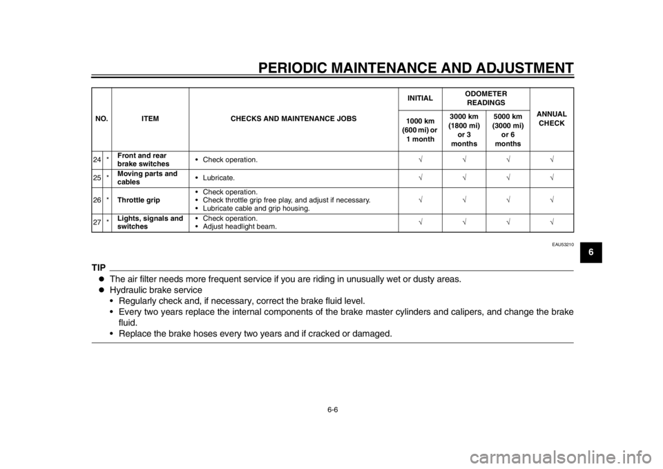
The air filter needs more frequent service if you are riding in unusually wet or dusty areas.
Hydraulic brake service
Regularly check and, if necessary, correct the brake fluid level.
Every two years replace the internal components of the brake master cylinders and calipers, and change the brake
fluid. Replace the brake hoses every tw o years and if cracked or damaged.
24 *Front and rear
brake switches Check operation.
25 * Moving parts and
cables Lubricate.
26 * Throttle grip Check operation.
Check throttle grip free play, and adjust if necessary.
Lubricate cable and grip housing.
27 * Lights, signals and
switches Check operation.
Adjust headlight beam.
NO. ITEM CHECKS AND MAINTENANCE JOBS
INITIAL
ODOMETER
READINGS
ANNUAL CHECK
1000 km
(600 mi) or
1 month 3000 km
(1800 mi) or 3
months 5000 km
(3000 mi) or 6
months
1DX-9-E0.book 6 ページ 2011年10月10日 月曜日 午後2時14分
Page 69 of 96
PERIODIC MAINTENANCE AND ADJUSTMENT
6-26
2
3
4
567
8
9
EAU23025
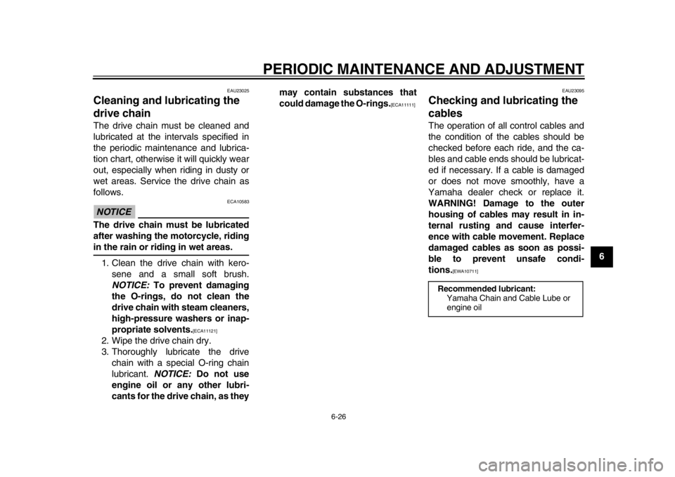
Cleaning and lubricating the
drive chain The drive chain must be cleaned and
lubricated at the intervals specified in
the periodic maintenance and lubrica-
tion chart, otherwise it will quickly wear
out, especially when riding in dusty or
wet areas. Service the drive chain as
follows.NOTICE
ECA10583
The drive chain must be lubricated
after washing the motorcycle, ridingin the rain or riding in wet areas.
1. Clean the drive chain with kero- sene and a small soft brush.
NOTICE: To prevent damaging
the O-rings, do not clean the
drive chain with steam cleaners,
high-pressure washers or inap-
propriate solvents.
[ECA11121]
2. Wipe the drive chain dry.
3. Thoroughly lubricate the drive chain with a special O-ring chain
lubricant. NOTICE: Do not use
engine oil or any other lubri-
cants for the drive chain, as they may contain substances that
could damage the O-rings.
[ECA11111]
EAU23095
Checking and lubricating the
cables The operation of all control cables and
the condition of the cables should be
checked before each ride, and the ca-
bles and cable ends should be lubricat-
ed if necessary. If a cable is damaged
or does not move smoothly, have a
Yamaha dealer check or replace it.
WARNING! Damage to the outer
housing of cables may result in in-
ternal rusting and cause interfer-
ence with cable movement. Replace
damaged cables as soon as possi-
ble to prevent unsafe condi-
tions.
[EWA10711]
Recommended lubricant:
Yamaha Chain and Cable Lube or
engine oil
1DX-9-E0.book 26 ページ 2011年10月10日 月曜日 午後2時14分
Page 78 of 96
PERIODIC MAINTENANCE AND ADJUSTMENT
6-35
1
2
3
4
56
7
8
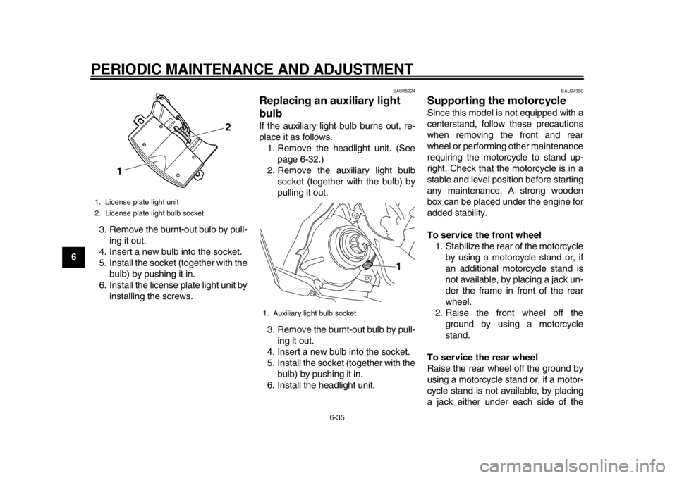
93. Remove the burnt-out bulb by pull-
ing it out.
4. Insert a new bulb into the socket.
5. Install the socket (together with the bulb) by pushing it in.
6. Install the license plate light unit by installing the screws.
EAU45224
Replacing an auxiliary light
bulb If the auxiliary light bulb burns out, re-
place it as follows.1. Remove the headlight unit. (See page 6-32.)
2. Remove the auxiliary light bulb socket (together with the bulb) by
pulling it out.
3. Remove the burnt-out bulb by pull- ing it out.
4. Insert a new bulb into the socket.
5. Install the socket (together with the bulb) by pushing it in.
6. Install the headlight unit.
EAU24350
Supporting the motorcycle Since this model is not equipped with a
centerstand, follow these precautions
when removing the front and rear
wheel or performing other maintenance
requiring the motorcycle to stand up-
right. Check that the motorcycle is in a
stable and level position before starting
any maintenance. A strong wooden
box can be placed under the engine for
added stability.
To service the front wheel 1. Stabilize the rear of the motorcycle by using a motorcycle stand or, if
an additional motorcycle stand is
not available, by placing a jack un-
der the frame in front of the rear
wheel.
2. Raise the front wheel off the ground by using a motorcycle
stand.
To service the rear wheel
Raise the rear wheel off the ground by
using a motorcycle stand or, if a motor-
cycle stand is not available, by placing
a jack either under each side of the
1. License plate light unit
2. License plate light bulb socket
1 2
1. Auxiliary light bulb socket
1
1DX-9-E0.book 35 ページ 2011年10月10日 月曜日 午後2時14分
Page 82 of 96
PERIODIC MAINTENANCE AND ADJUSTMENT
6-39
1
2
3
4
56
7
8
9
EAU25871
Troubleshooting Although Yamaha motorcycles receive
a thorough inspection before shipment
from the factory, trouble may occur dur-
ing operation. Any problem in the fuel,
compression, or ignition systems, for
example, can cause poor starting and
loss of power.
The following troubleshooting charts
represent quick and easy procedures
for checking these vital systems your-
self. However, should your motorcycle
require any repair, take it to a Yamaha
dealer, whose skilled technicians have
the necessary tools, experience, and
know-how to service the motorcycle
properly.
Use only genuine Yamaha replace-
ment parts. Imitation parts may look like
Yamaha parts, but they are often inferi-
or, have a shorter service life and can
lead to expensive repair bills.
WARNING
EWA15141
When checking the fuel system, do
not smoke, and make sure there are
no open flames or sparks in the ar-
ea, including pilot lights from waterheaters or furnaces. Gasoline or
gasoline vapors can ignite or ex-
plode, causing severe injury or
property damage.
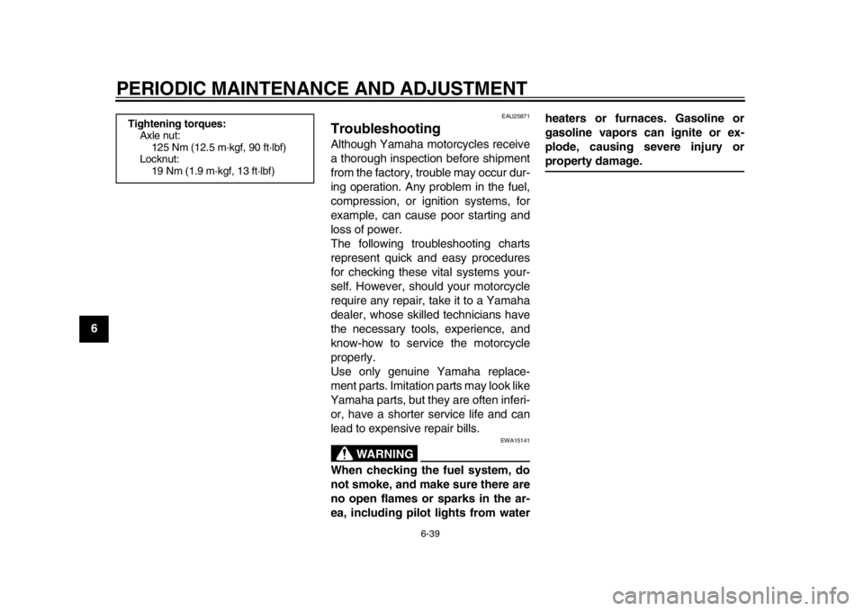
Tightening torques:
Axle nut:125 Nm (12.5 m·kgf, 90 ft·lbf)
Locknut:
19 Nm (1.9 m·kgf, 13 ft·lbf)
1DX-9-E0.book 39 ページ 2011年10月10日 月曜日 午後2時14分
Page 89 of 96
8-1
2
3
4
5
6
789
SPECIFICATIONS
EAU50973
Dimensions:Overall length: 2315 mm (91.1 in)
Overall width: 825 mm (32.5 in)
Overall height: 1275 mm (50.2 in)
Seat height:
960 mm (37.8 in)
Wheelbase: 1475 mm (58.1 in)
Ground clearance: 335 mm (13.19 in)
Minimum turning radius:
2400 mm (94.5 in)Weight:Curb weight: 129 kg (284 lb)Noise and vibration level:Noise level (77/311/EEC): 80.2 dB(A)
Vibration on seat (EN1032, ISO5008): Will not exceed 0.5 m/s
2
Vibration on handlebar (EN1032, ISO5008): Will not exceed 2.5 m/s
2
Engine:Engine type: Liquid cooled 4-stroke, DOHC
Cylinder arrangement:
Single cylinder
Displacement: 449 cm
3
Bore stroke:
95.0 63.4 mm (3.74 2.50 in) Compression ratio:
12.30 : 1
Starting system:
Electric starter and kickstarter
Lubrication system: Dry sump
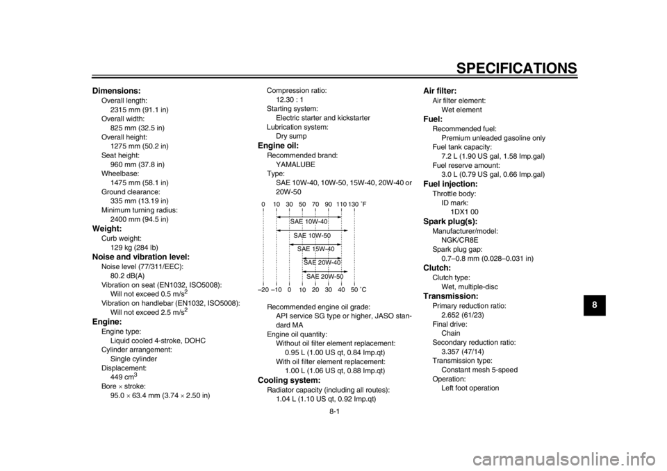
Engine oil:Recommended brand:
YAMALUBE
Type: SAE 10W-40, 10W-50, 15W-40, 20W-40 or
20W-50
Recommended engine oil grade: API service SG type or higher, JASO stan-
dard MA
Engine oil quantity: Without oil filter element replacement:
0.95 L (1.00 US qt, 0.84 Imp.qt)
With oil filter element replacement: 1.00 L (1.06 US qt, 0.88 Imp.qt)Cooling system:Radiator capacity (including all routes): 1.04 L (1.10 US qt, 0.92 Imp.qt)
Air filter:Air filter element:
Wet elementFuel:Recommended fuel: Premium unleaded gasoline only
Fuel tank capacity:
7.2 L (1.90 US gal, 1.58 Imp.gal)
Fuel reserve amount: 3.0 L (0.79 US gal, 0.66 Imp.gal)Fuel injection:Throttle body:
ID mark: 1DX1 00Spark plug(s):Manufacturer/model: NGK/CR8E
Spark plug gap: 0.7–0.8 mm (0.028–0.031 in)Clutch:Clutch type: Wet, multiple-discTransmission:Primary reduction ratio:
2.652 (61/23)
Final drive: Chain
Secondary reduction ratio: 3.357 (47/14)
Transmission type:
Constant mesh 5-speed
Operation: Left foot operation
–20 –10 0 1020 30 40 50 �C
10 30 50 70 90 110
0 130 �F
SAE 20W-50SAE 20W-40SAE 15W-40SAE 10W-40SAE 10W-50
1DX-9-E0.book 1 ページ 2011年10月10日 月曜日 午後2時14分