warning light YAMAHA WR 450F 2016 User Guide
[x] Cancel search | Manufacturer: YAMAHA, Model Year: 2016, Model line: WR 450F, Model: YAMAHA WR 450F 2016Pages: 426, PDF Size: 10.86 MB
Page 321 of 426

FUEL TANK
8-4
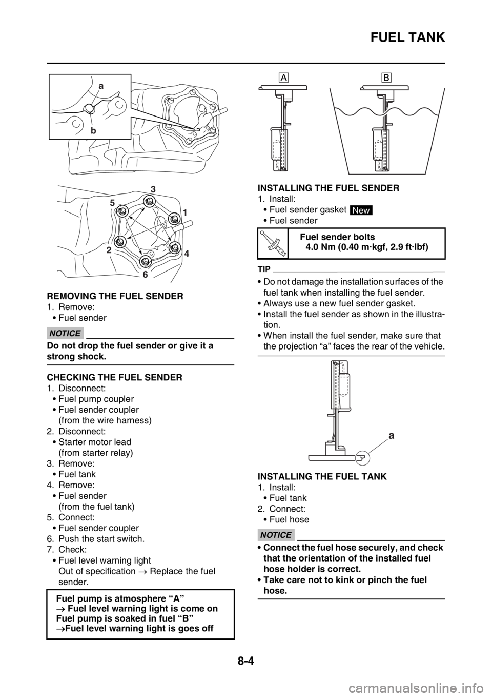
EAS2GC1344REMOVING THE FUEL SENDER
1. Remove:• Fuel sender
ECA
NOTICE
Do not drop the fuel sender or give it a
strong shock.
EAS2GC1345CHECKING THE FUEL SENDER
1. Disconnect:• Fuel pump coupler
• Fuel sender coupler
(from the wire harness)
2. Disconnect: • Starter motor lead
(from starter relay)
3. Remove: • Fuel tank
4. Remove: • Fuel sender(from the fuel tank)
5. Connect: • Fuel sender coupler
6. Push the start switch.
7. Check:
• Fuel level warning lightOut of specification Replace the fuel
sender.
EAS2GC1346INSTALLING THE FUEL SENDER
1. Install: • Fuel sender gasket
• Fuel sender
TIP
• Do not damage the installation surfaces of the
fuel tank when installing the fuel sender.
• Always use a new fuel sender gasket.
• Install the fuel sender as shown in the illustra-
tion.
• When install the fuel sender, make sure that
the projection “a” faces the rear of the vehicle.
EAS2GC1347INSTALLING THE FUEL TANK
1. Install: • Fuel tank
2. Connect:
• Fuel hose
ECA
NOTICE
• Connect the fuel hose securely, and check that the orientation of the installed fuel
hose holder is correct.
• Take care not to kink or pinch the fuel
hose.
Fuel pump is atmosphere “A”
Fuel level warning light is come on
Fuel pump is soaked in fuel “B”
Fuel level warning light is goes off
a
b
4
1
2
6
5 3
Fuel sender bolts
4.0 Nm (0.40 m·kgf, 2.9 ft·lbf)
New
T R..
a
Page 351 of 426

SIGNALING SYSTEM
9-21
1. Joint connector
2. Joint connector
3. Joint connector
7. Main relay
9. Battery
10.Frame ground
11.Starter relay
12.Main fuse
15.Indicator light
17.Fuel level warning light
18.Resistor
19.Fuel sender
22.ECU (engine control unit)
30.Joint connector
42.Joint connector
46.Speed sensor
47.Multi-function display
48.Frame ground
50.Negative battery lead
Page 353 of 426

SIGNALING SYSTEM
9-23
The fuel level warning light fails to come on.
1. Check the fuel sender.Refer to “CHECKING THE FUEL
SENDER” on page 9-77. NG
Replace the fuel sender assembly.
OK
2. Check the resistor. Refer to “CHECKING THE RESIST-
ER” on page 9-77. NG
Replace the resistor.
OK
3. Check the entire signaling system’s wiring.
Refer to “CIRCUIT DIAGRAM” on
page 9-20. NG
Properly connect or repair the signaling
system’s wiring.
OK
Replace the indicator light assembly.
Page 359 of 426

FUEL INJECTION SYSTEM
9-29
1. Joint connector
2. Joint connector
3. Joint connector
4. AC magneto
7. Main relay
9. Battery
10.Frame ground
11.Starter relay
12.Main fuse
15.Indicator light
16.Engine trouble warning light
22.ECU (engine control unit)
25.Injector
30.Joint connector
31.Intake air temperature sensor
32.Coolant temperature sensor
33.Throttle position sensor
34.Intake air pressure sensor
35.Lean angle sensor
36.Engine stop switch
37.Neutral switch
38.Diode
39.Starting circuit cut-off relay
40.Clutch switch
42.Joint connector
48.Frame ground
50.Negative battery lead
Page 360 of 426

FUEL INJECTION SYSTEM
9-30
EAS2GC1375ECU SELF-DIAGNOSTIC FUNCTION
The ECU is equipped with a self-diagnostic function in order to ensure that the fuel injection system
is operating normally. If this function detects a malfunction in the system, it immediately operates the
engine under substitute characteristics and illuminat es the engine trouble warning light to alert the
rider that a malfunction has occurred in the syst em. Once a malfunction has been detected, a fault
code number is stored in the memory of the ECU.
• To inform the rider that the fuel injection system is not functioning, the engine trouble warning light
flashes while the start switch is being pushed to start the engine.
• If a malfunction is detected in the system by th e self-diagnostic function, the ECU provides an ap-
propriate substitute characteristic operation, and al erts the rider of the detected malfunction by illu-
minating the engine trouble warning light.
Engine trouble warning light indication and fuel injection system operation
* The warning light flashes when any one of the foll owing conditions is present and the start switch
is pushed:
Checking the engine trouble warning light
The engine trouble warning light comes on for around 2 seconds when pushing the start switch to
turn on the meter light and the engine trouble warning light comes on while the start switch is being
pushed. Warning light indica-
tion ECU operation Fuel injection opera-
tion Vehicle operation
Flashing* Warning provided when unable to start
engine Operation stopped Cannot be operated
Remains on Malfunction detected Operated with substi- tute characteristics in
accordance with the
description of the mal-
functionCan or cannot be oper-
ated depending on the
fault code
12: Crankshaft position sensor 41: Lean angle sensor (open or short circuit)
30: Lean angle sensor (latch up detected) 50: ECU internal malfunction
(faulty ECU memory)
33: Ignition coil (Malfunction detected in the primary wire
of the ignition coil)
a. The meter light does not come on.
b. The meter light comes on.
c. Light OFF
d. Light ON for 2 seconds
ab
cd c
Page 361 of 426

FUEL INJECTION SYSTEM
9-31
ECU detects an abnormal signal from a sensor
If the ECU detects an abnormal signal from a sensor while the vehicle is being driven, the ECU illu-
minates the engine trouble warning light and provides the engine with alternate operating instructions
that are appropriate for the type of malfunction.
When an abnormal signal is received from a sensor, the ECU processes the specified values that are
programmed for each sensor in order to provide the engine with alternate operating instructions that
enable the engine to continue operating or stop operating, depending on the conditions.
EAS2GC1376TROUBLESHOOTING METHOD
The engine operation is not normal and the engine trouble warning light comes on.
1. Check: • Fault code number
▼▼▼▼▼▼▼▼▼▼▼▼▼▼▼▼▼▼▼▼▼▼▼▼▼▼▼▼▼▼▼▼▼▼▼▼▼▼▼▼▼▼▼▼▼▼▼▼▼▼▼▼▼▼▼▼▼▼▼▼▼▼▼▼▼▼▼▼
a. Connect the Yamaha diagnostic tool. Refer to “YAMAHA DIAGNOSTIC TOOL” on page 9-32.
b. Check the fault code number disp layed on the Yamaha diagnostic tool.
c. Identify the faulty system with the fault code number.
d. Identify the probable cause of the malfunction.
▲▲▲▲▲▲▲▲▲▲▲▲▲▲▲▲▲▲▲▲▲▲▲▲▲▲▲▲▲▲▲▲▲▲▲▲▲▲▲▲▲▲▲▲▲▲▲▲▲▲▲▲▲▲▲▲▲▲▲▲▲▲▲▲▲▲▲▲
2. Check and repair the probable cause of the malfunction.
3. Perform the reinstatement action for the fuel injection system. Refer to “Confirmation of service
completion” in the appropriate table in “TROUBLESHOOTING DETAILS” on page 9-35.
4. After pushing the engine stop switch, push the start switch to check whether the fault code no. is
displayed.
TIP
If another fault code number is displayed, repeat steps (1) to (4) until no fault code number is dis-
played.
5. Erase the malfunction history in the diagnostic mode. Refer to “SENSOR OPERATION TABLE”
(Diagnostic code No.62).
TIP
Turning off the meter light will not erase the malfunction history.
The engine operation is not normal, but the engine trouble warning light does not come on.
1. Check the operation of the following sensors an d actuators in the diagnostic mode. Refer to
“TROUBLESHOOTING DETAILS” on page 9-35.
If a malfunction is detected in the sensors or ac tuators, repair or replace all faulty parts.
If no malfunction is detected in the sensors and ac tuators, check and repair the inner parts of the
engine. Fault code No. No fault code No.
Check and repair. Refer to “TROUBLESHOOT-
ING DETAILS” on page 9-35.
Monitor the operation of the sensors and actua-
tors in the diagnostic mode. Refer to “TROU-
BLESHOOTING DETAILS” on page 9-35 and
“LIST OF SELF-DIAGNOSTIC AND FAIL-SAFE
ACTIONS” on page 10-5. Check and repair.
01: Throttle position sensor signal (throttle angle)
30: Ignition coil
36: Injector
Page 375 of 426

FUEL INJECTION SYSTEM
9-45
2 Installed condition of lean an-gle sensor. Check the installed direction
and condition of the sensor. Push the start switch.
Fault code number is not dis-
played
Service is finished.
Fault code number is dis-
played Go to item 3.
3 Defective lean angle sensor. Execute the diagnostic mode. (Code No. 08)
Replace if defective.
Refer to “CHECKING THE
LEAN ANGLE SENSOR” on
page 9-75.Push the start switch.
Fault code number is not dis-
played
Service is finished.
Fault code number is dis-
played Go to item 4.
4 Malfunction in ECU. Replace the ECU.
Fault code No. 33
Item Ignition coil: open or short circuit detected in the primary lead
of the ignition coil.
Fail-safe system Unable to start engine
Unable to drive vehicle
Diagnostic code No. 30
Actuation Actuates the ignition coil five times at one-second intervals.
The engine trouble warning light and the “WARNING” on the
Yamaha diagnostic tool screen come on each time the ignition coil
is actuated.
Procedure Check that a spark is generated five times.
• Connect an ignition checker.
Item Probable cause of malfunc-
tion and check Maintenance jobConfirmation of service
completion
1 Connection of ignition coil coupler.
Check the locking condition
of the coupler.
Disconnect the coupler and
check the pins (bent or bro-
ken terminals and locking
condition of the pins). Improperly connected
Connect the coupler securely
or repair/replace the wire har-
ness. Start the engine and let it idle
for approximately 5 seconds.
Fault code number is not dis-
played
Service is finished.
Fault code number is dis-
played Go to item 2.
2 Connection of wire harness ECU coupler.
Check the locking condition
of the coupler.
Disconnect the coupler and
check the pins (bent or bro-
ken terminals and locking
condition of the pins). Improperly connected
Connect the coupler securely
or repair/replace the wire har-
ness. Start the engine and let it idle
for approximately 5 seconds.
Fault code number is not dis-
played
Service is finished.
Fault code number is dis-
played Go to item 3.
Fault code No.
30
Item Latch up detected.
Page 377 of 426

FUEL INJECTION SYSTEM
9-47
TIP
Disconnect the fuel pump coupler when this diagnostic tool is used.
Fault code No. 39
Item Injector: open or short circuit detected.
Fail-safe system Unable to start engine
Unable to drive vehicle
Diagnostic code No. 36
Actuation Actuates injector five times at one-second intervals.
The engine trouble warning light and the “WARNING” on the
Yamaha diagnostic tool screen come on each time the injector is
actuated.
Procedure Check that injector is actuated five times by listening for the oper-
ating sound.
Item Probable cause of malfunc-
tion and check Maintenance jobConfirmation of service
completion
1 Connection of injector cou- pler.
Check the locking condition
of the coupler.
Disconnect the coupler and
check the pins (bent or bro-
ken terminals and locking
condition of the pins). Improperly connected
Connect the coupler securely
or repair/replace the wire har-
ness. Execute the diagnostic mode
(Code No. 36).
No operating sound
Go to
item 2.
Operating sound Go to
item 6.
2 Defective injector. Measure the fuel injector re- sistance.
Replace if out of specifica-
tion.
Refer to “CHECKING THE
FUEL INJECTOR” on page 9-
81.Execute the diagnostic mode
(Code No. 36).
No operating sound
Go to
item 3.
Operating sound Go to
item 6.
3 Connection of wire harness ECU coupler.
Check the locking condition
of the coupler.
Disconnect the coupler and
check the pins (bent or bro-
ken terminals and locking
condition of the pins). Improperly connected
Connect the coupler securely
or repair/replace the wire har-
ness. Execute the diagnostic mode
(Code No. 36).
No operating sound
Go to
item 4.
Operating sound Go to
item 6.
4 Wire harness continuity. Open or short circuit Re-
place the wire harness.
Between injector coupler and
ECU coupler.
red/black–red/black
red–red/blue Execute the diagnostic mode
(Code No. 36).
No operating sound
Go to
item 5.
Operating sound Go to
item 6.
5 Malfunction in ECU. Replace the ECU. —
6 Delete the fault code. — Start the engine and let it idle for approximately 5 seconds.
Check that the fault code
number is not displayed.
Page 397 of 426

ELECTRICAL COMPONENTS
9-67
EAS27990CHECKING THE BULBS AND BULB SOCK-
ETS
TIP
Do not check any of the lights that use LEDs.
Check each bulb and bulb socket for damage
or wear, proper connections, and also for con-
tinuity between the terminals.
Damage/wear Repair or replace the bulb,
bulb socket or both.
Improperly connected Properly connect.
No continuity Repair or replace the bulb,
bulb socket or both.
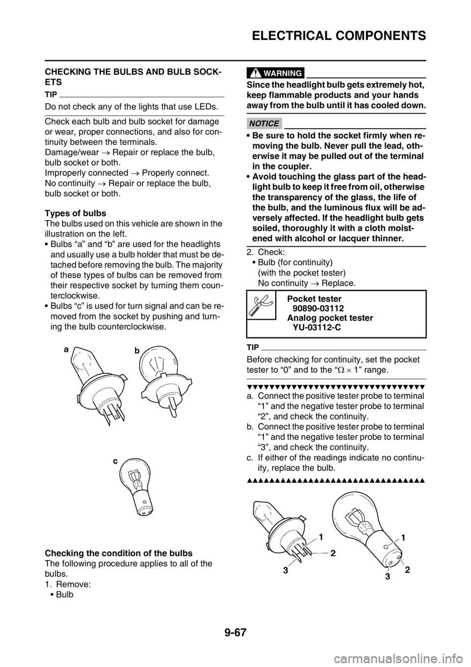
Types of bulbs
The bulbs used on this v ehicle are shown in the
illustration on the left.
• Bulbs “a” and “b” are used for the headlights
and usually use a bulb holder that must be de-
tached before removing the bulb. The majority
of these types of bulbs can be removed from
their respective socket by turning them coun-
terclockwise.
• Bulbs “c” is used for turn signal and can be re- moved from the socket by pushing and turn-
ing the bulb counterclockwise.
Checking the condition of the bulbs
The following procedure applies to all of the
bulbs.
1. Remove: •Bulb
EWA
WARNING
Since the headlight bulb gets extremely hot,
keep flammable products and your hands
away from the bulb until it has cooled down.
ECA
NOTICE
• Be sure to hold the socket firmly when re-moving the bulb. Never pull the lead, oth-
erwise it may be pulled out of the terminal
in the coupler.
• Avoid touching the glass part of the head- light bulb to keep it free from oil, otherwise
the transparency of the glass, the life of
the bulb, and the luminous flux will be ad-
versely affected. If the headlight bulb gets
soiled, thoroughly it with a cloth moist-
ened with alcohol or lacquer thinner.
2. Check: • Bulb (for continuity)(with the pocket tester)
No continuity Replace.
TIP
Before checking for continuity, set the pocket
tester to “0” and to the “ 1” range.
▼▼▼▼▼▼▼▼▼▼▼▼▼▼▼▼▼▼▼▼▼▼▼▼▼▼▼▼▼▼▼▼
a. Connect the positive tester probe to terminal
“1” and the negative tester probe to terminal
“2”, and check the continuity.
b. Connect the positive tester probe to terminal “1” and the negative tester probe to terminal
“3”, and check the continuity.
c. If either of the readings indicate no continu- ity, replace the bulb.
▲▲▲▲▲▲▲▲▲▲▲▲▲▲▲▲▲▲▲▲▲▲▲▲▲▲▲▲▲▲▲▲
Pocket tester90890-03112
Analog pocket tester YU-03112-C
Page 398 of 426

ELECTRICAL COMPONENTS
9-68
Checking the condition of the bulb sockets
The following procedure applies to all of the
bulb sockets.
1. Check:• Bulb socket (for continuity)(with the pocket tester)
No continuity Replace.
TIP
Check each bulb socket for continuity in the
same manner as described in the bulb section;
however, note the following.
▼▼▼▼▼▼▼▼▼▼▼▼▼▼▼▼▼▼▼▼▼▼▼▼▼▼▼▼▼▼▼▼
a. Install a good bulb into the bulb socket.
b. Connect the pocket tester probes to the re-
spective leads of the bulb socket.
c. Check the bulb socket for continuity. If any of
the readings indicate no continuity, replace
the bulb socket.
▲▲▲▲▲▲▲▲▲▲▲▲▲▲▲▲▲▲▲▲▲▲▲▲▲▲▲▲▲▲▲▲
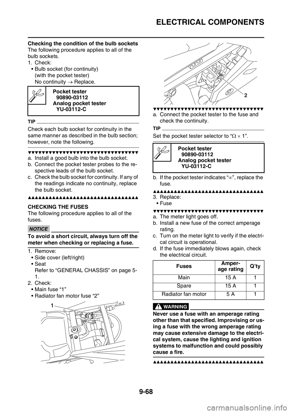
EAS2GC1385CHECKING THE FUSES
The following procedure applies to all of the
fuses.
ECA
NOTICE
To avoid a short circuit, always turn off the
meter when checking or replacing a fuse.
1. Remove: • Side cover (left/right)
• SeatRefer to “GENERAL CHASSIS” on page 5-
1.
2. Check: • Main fuse “1”
• Radiator fan motor fuse “2”
▼▼▼▼▼▼▼▼▼▼▼▼▼▼▼▼▼▼▼▼▼▼▼▼▼▼▼▼▼▼▼▼
a. Connect the pocket tester to the fuse and check the continuity.
TIP
Set the pocket tester selector to “ 1”.
b. If the pocket tester indicates “ ”, replace the
fuse.
▲▲▲▲▲▲▲▲▲▲▲▲▲▲▲▲▲▲▲▲▲▲▲▲▲▲▲▲▲▲▲▲
3. Replace: • Fuse
▼▼▼▼▼▼▼▼▼▼▼▼▼▼▼▼▼▼▼▼▼▼▼▼▼▼▼▼▼▼▼▼
a. The meter light goes off.
b. Install a new fuse of the correct amperage rating.
c. Turn on the meter light to verify if the electri- cal circuit is operational.
d. If the fuse immediatel y blows again, check
the electrical circuit.
EWA
WARNING
Never use a fuse with an amperage rating
other than that specified. Improvising or us-
ing a fuse with the wrong amperage rating
may cause extensive damage to the electri-
cal system, cause the lighting and ignition
systems to malfunction and could possibly
cause a fire.
▲▲▲▲▲▲▲▲▲▲▲▲▲▲▲▲▲▲▲▲▲▲▲▲▲▲▲▲▲▲▲▲
Pocket tester 90890-03112
Analog pocket tester YU-03112-C
1
Pocket tester90890-03112
Analog pocket tester YU-03112-C
Fuses Amper-
age rating Q’ty
Main 15 A 1
Spare 15 A 1
Radiator fan motor 5 A 1
2