check YAMAHA WR 450F 2016 Owners Manual
[x] Cancel search | Manufacturer: YAMAHA, Model Year: 2016, Model line: WR 450F, Model: YAMAHA WR 450F 2016Pages: 426, PDF Size: 10.86 MB
Page 7 of 426

EAS2GC1005
SAFETY INFORMATION
THIS MACHINE IS DESIGNED STRICTLY FOR COMPETITION USE, ONLY ON A CLOSED
COURSE. It is illegal for this machine to be operat ed on any public street, road, or highway. Off-road
use on public lands may also be illegal. Pl ease check local regulations before riding.
• THIS MACHINE IS TO BE OPERATED BY AN EXPERIENCED RIDER ONLY. Do not attempt to operate this machine at maximum power until you are totally familiar with its char-
acteristics.
• THIS MACHINE IS DESIGNED TO BE RIDDEN BY THE OPERATOR ONLY. Do not carry passengers on this machine.
• ALWAYS WEAR PROTECTIVE APPAREL. When operating this machine, always wear an approved helmet with goggles or a face shield. Also
wear heavy boots, gloves, and protective clothing. Al ways wear proper fitting clothing that will not
be caught in any of the moving parts or controls of the machine.
• ALWAYS MAINTAIN YOUR MACHINE IN PROPER WORKING ORDER. For safety and reliability, the machine must be properly maintained. Always perform the pre-oper-
ation checks indicated in this manual.
Correcting a mechanical problem before you ride may prevent an accident.
• GASOLINE IS HIGHLY FLAMMABLE. Always turn off the engine while refueling. Take care to not spill any gasoline on the engine or ex-
haust system. Never refuel in the vicini ty of an open flame, or while smoking.
• GASOLINE CAN CAUSE INJURY. If you should swallow some gasoline, inhale excess gasoline vapors, or allow any gasoline to get
into your eyes, contact a doctor immediately. If any gasoline spills onto your skin or clothing, imme-
diately wash skin areas with soap and water, and change your clothes.
• ONLY OPERATE THE MACHINE IN AN AREA WITH ADEQUATE VENTILATION.
Never start the engine or let it run for any length of time in an enclosed area. Exhaust fumes are
poisonous. These fumes contain carbon monoxide, whic h by itself is odorless and colorless. Car-
bon monoxide is a dangerous gas which can cause unconsciousness or can be lethal.
• PARK THE MACHINE CAREFULLY; TURN OFF THE ENGINE. Always turn off the engine if you are going to leave the machine. Do not park the machine on a slope
or soft ground as it may fall over.
• THE ENGINE, EXHAUST PIPE AND MUFFLER WILL BE VERY HOT AFTER THE ENGINE HAS BEEN RUN.
Be careful not to touch them or to allow any clothing item to contact them during inspection or repair.
• PROPERLY SECURE THE MACHINE BEFORE TRANSPORTING IT. For safety, drain the gasoline from the fuel tank before transporting the vehicle.
Page 8 of 426
EAS2GC1006
HOW TO USE THIS MANUAL
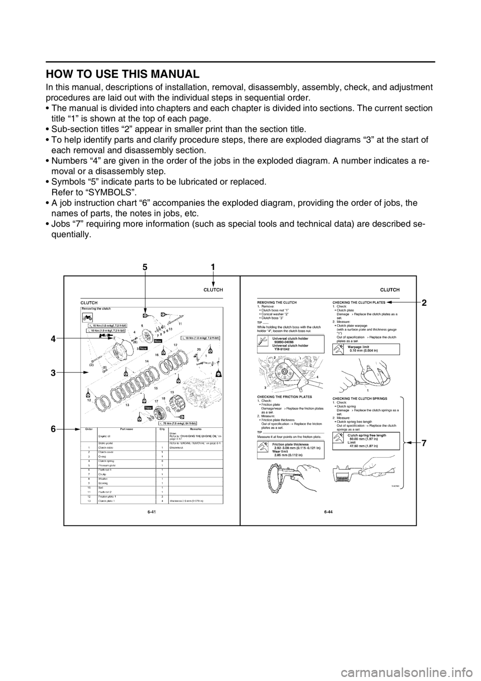
In this manual, descriptions of installation, removal, disassembly, assembly, check, and adjustment
procedures are laid out with the individual steps in sequential order.
• The manual is divided into chapters and each chapt er is divided into sections. The current section
title “1” is shown at the top of each page.
• Sub-section titles “2” appear in smaller print than the section title.
• To help identify parts and clarify procedure steps, there are exploded diagrams “3” at the start of
each removal and disassembly section.
• Numbers “4” are given in the order of the jobs in the exploded diagram. A number indicates a re-
moval or a disassembly step.
• Symbols “5” indicate parts to be lubricated or replaced. Refer to “SYMBOLS”.
• A job instruction chart “6” accompanies the ex ploded diagram, providing the order of jobs, the
names of parts, the notes in jobs, etc.
• Jobs “7” requiring more information (such as special tools and technical data) are described se-
quentially.
1
7
3
4
6
2
5
Page 11 of 426

1
2
3
4
5
6
7
8
9
10
TABLE OF CONTENS
GENERAL INFORMATION
SPECIFICATIONS
PERIODIC CHECKS AND
ADJUSTMENTS
TUNING
CHASSIS
ENGINE
COOLING SYSTEM
FUEL SYSTEM
ELECTRICAL SYSTEM
TROUBLESHOOTING
Page 14 of 426

MULTI-FUNCTION DISPLAY......................................................................... 1-21
DESCRIPTION ......................................................................................... 1-21
BASIC MODE ........................................................................................... 1-21
CHANGEOVER TO BASIC MODE /RACE MODE.................................... 1-22
RACE MODE ............................................................................................ 1-23
FUNCTION DIAGRAM ............................................................................. 1-26
STARTING AND BREAK-IN .......................................................................... 1-28
FUEL ........................................................................................................ 1-28
HANDLING NOTE .................................................................................... 1-28
AIR FILTER MAINTENANCE ................................................................... 1-28
STARTING A COLD ENGINE .................................................................. 1-28
STARTING A WARM ENGINE ................................................................. 1-30
BREAK-IN PROCEDURES .... .................................................................. 1-30
MAINTENANCE AFTER BREAK-IN .............................................................. 1-31
MAJOR MAINTENANCE .......................................................................... 1-31
TORQUE-CHECK POINTS ............................................................................ 1-32
MOTORCYCLE CARE AND STORAGE ........................................................ 1-34
CARE........................................................................................................ 1-34
STORAGE ................................................................................................ 1-35
Page 18 of 426
DESCRIPTION
1-4
EAS2GC1009
DESCRIPTION
TIP
Designs and specifications of the vehicle are subject to change without notice. Therefore, please
note that the descriptions in this manual may be different from those for the vehicle you have pur-
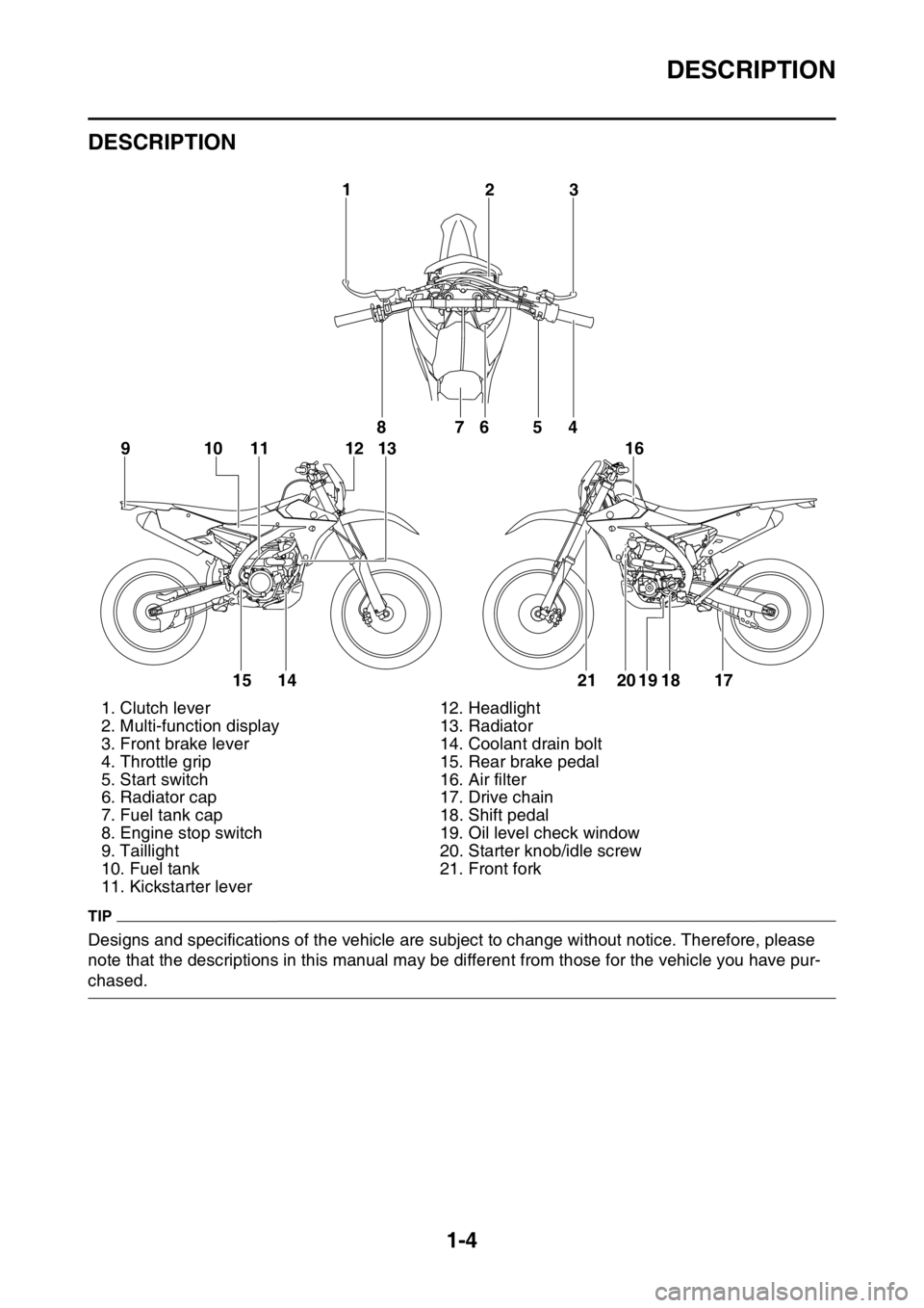
chased.1. Clutch lever 12. Headlight
2. Multi-function display 13. Radiator
3. Front brake lever 14. Coolant drain bolt
4. Throttle grip 15. Rear brake pedal
5. Start switch 16. Air filter
6. Radiator cap 17. Drive chain
7. Fuel tank cap 18. Shift pedal
8. Engine stop switch 19. Oil level check window
9. Taillight 20. Starter knob/idle screw
10. Fuel tank 21. Front fork
11. Kickstarter lever
32
1
8
10
91 112 1376
54
15 14 21 20 19 18 17 16
Page 21 of 426
IMPORTANT INFORMATION
1-7
EAS20180
IMPORTANT INFORMATION
EAS2GC1020PREPARATION FOR REMOVAL AND DIS-
ASSEMBLY
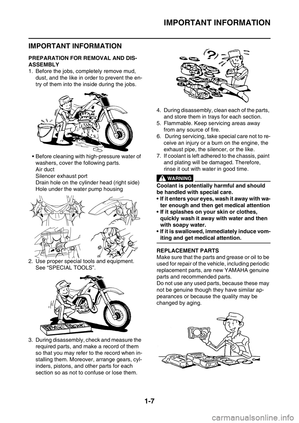
1. Before the jobs, completely remove mud, dust, and the like in order to prevent the en-
try of them into the inside during the jobs.
• Before cleaning with high-pressure water of washers, cover the following parts.
Air duct
Silencer exhaust port
Drain hole on the cylinder head (right side)
Hole under the water pump housing
2. Use proper special tools and equipment. See “SPECIAL TOOLS”.
3. During disassembly, check and measure the required parts, and make a record of them
so that you may refer to the record when in-
stalling them. Moreover, arrange gears, cyl-
inders, pistons, and other parts for each
section so as not to confuse or lose them. 4. During disassembly, clean each of the parts,
and store them in trays for each section.
5. Flammable. Keep servicing areas away from any source of fire.
6. During servicing, take special care not to re-
ceive an injury or a burn on the engine, the
exhaust pipe, the silencer, or the like.
7. If coolant is left adhered to the chassis, paint
and plating will be damaged. Therefore,
rinse it out with water in good time.
EWA
WARNING
Coolant is potentially harmful and should
be handled with special care.
• If it enters your eyes, wash it away with wa-ter enough and then get medical attention
• If it splashes on your skin or clothes,
quickly wash it away with water and then
with soapy water.
• If it is swallowed, immediately induce vom-
iting and get medical attention.
EAS2GC1021REPLACEMENT PARTS
Make sure that the parts and grease or oil to be
used for repair of the vehicle, including periodic
replacement parts, are new YAMAHA genuine
parts and recommended parts.
Do not use any used parts, because these may
not be genuine though they have similar ap-
pearances or because the quality may be
changed by aging.
Page 24 of 426
BASIC SERVICE INFORMATION
1-10
ECA
NOTICE
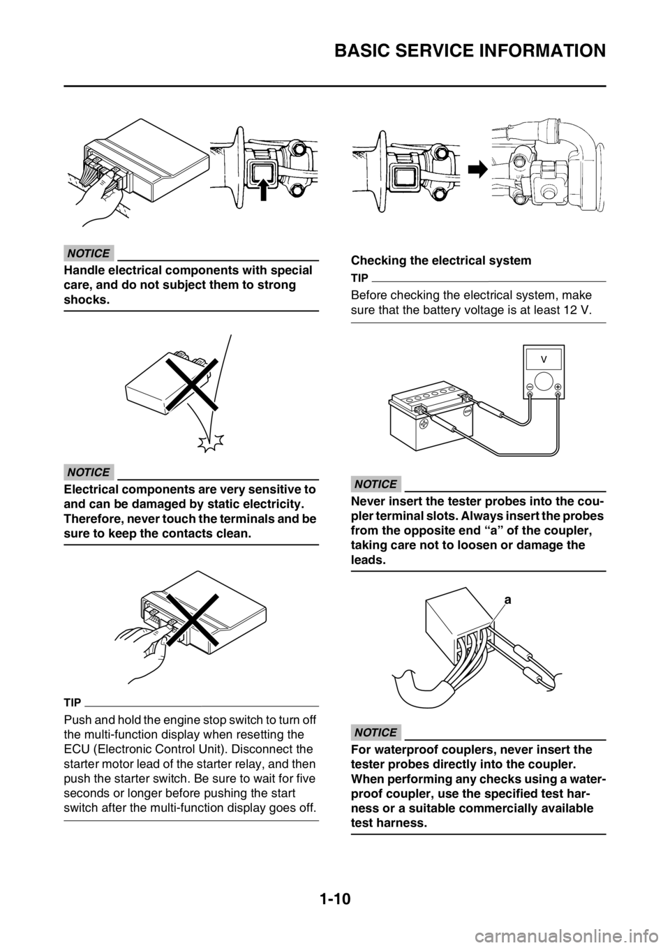
Handle electrical components with special
care, and do not subject them to strong
shocks.
ECA
NOTICE
Electrical components are very sensitive to
and can be damaged by static electricity.
Therefore, never touch the terminals and be
sure to keep the contacts clean.
TIP
Push and hold the engine stop switch to turn off
the multi-function display when resetting the
ECU (Electronic Control Unit). Disconnect the
starter motor lead of the starter relay, and then
push the starter switch. Be sure to wait for five
seconds or longer before pushing the start
switch after the multi-function display goes off.Checking the electrical system
TIP
Before checking the electrical system, make
sure that the battery voltage is at least 12 V.
ECA
NOTICE
Never insert the tester probes into the cou-
pler terminal slots. Always insert the probes
from the opposite end “a” of the coupler,
taking care not to loosen or damage the
leads.
ECA
NOTICE
For waterproof couplers, never insert the
tester probes directly into the coupler.
When performing any checks using a water-
proof coupler, use the specified test har-
ness or a suitable commercially available
test harness.
a
Page 25 of 426
BASIC SERVICE INFORMATION
1-11
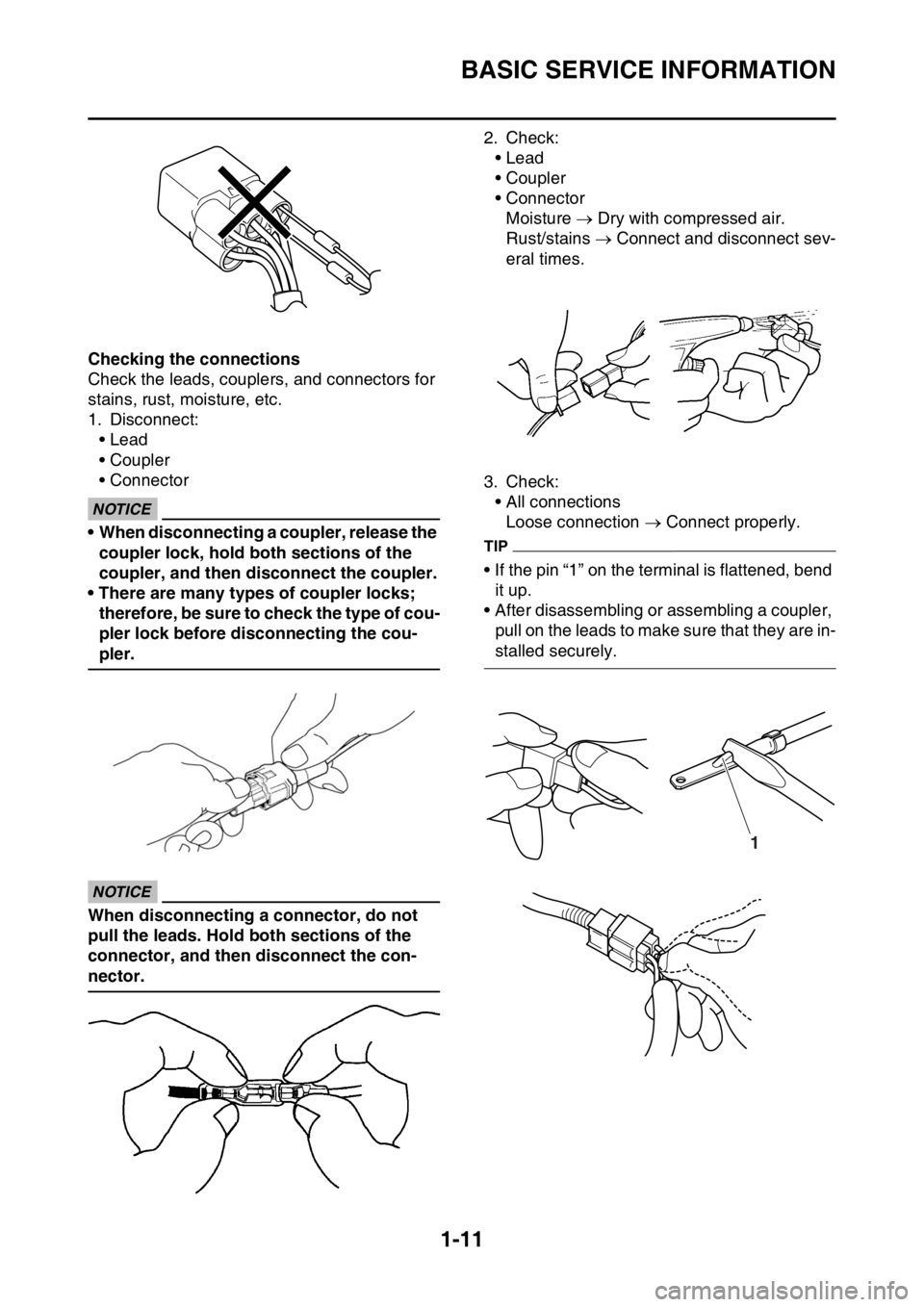
Checking the connections
Check the leads, couplers, and connectors for
stains, rust, moisture, etc.
1. Disconnect:• Lead
• Coupler
• Connector
ECA
NOTICE
• When disconnecting a coupler, release the
coupler lock, hold both sections of the
coupler, and then disconnect the coupler.
• There are many types of coupler locks; therefore, be sure to check the type of cou-
pler lock before disconnecting the cou-
pler.
ECA
NOTICE
When disconnecting a connector, do not
pull the leads. Hold both sections of the
connector, and then disconnect the con-
nector. 2. Check:
• Lead
• Coupler
• ConnectorMoisture Dry with compressed air.
Rust/stains Connect and disconnect sev-
eral times.
3. Check: • All connectionsLoose connection Connect properly.
TIP
• If the pin “1” on the terminal is flattened, bend
it up.
• After disassembling or assembling a coupler,
pull on the leads to make sure that they are in-
stalled securely.
1
Page 26 of 426
BASIC SERVICE INFORMATION
1-12
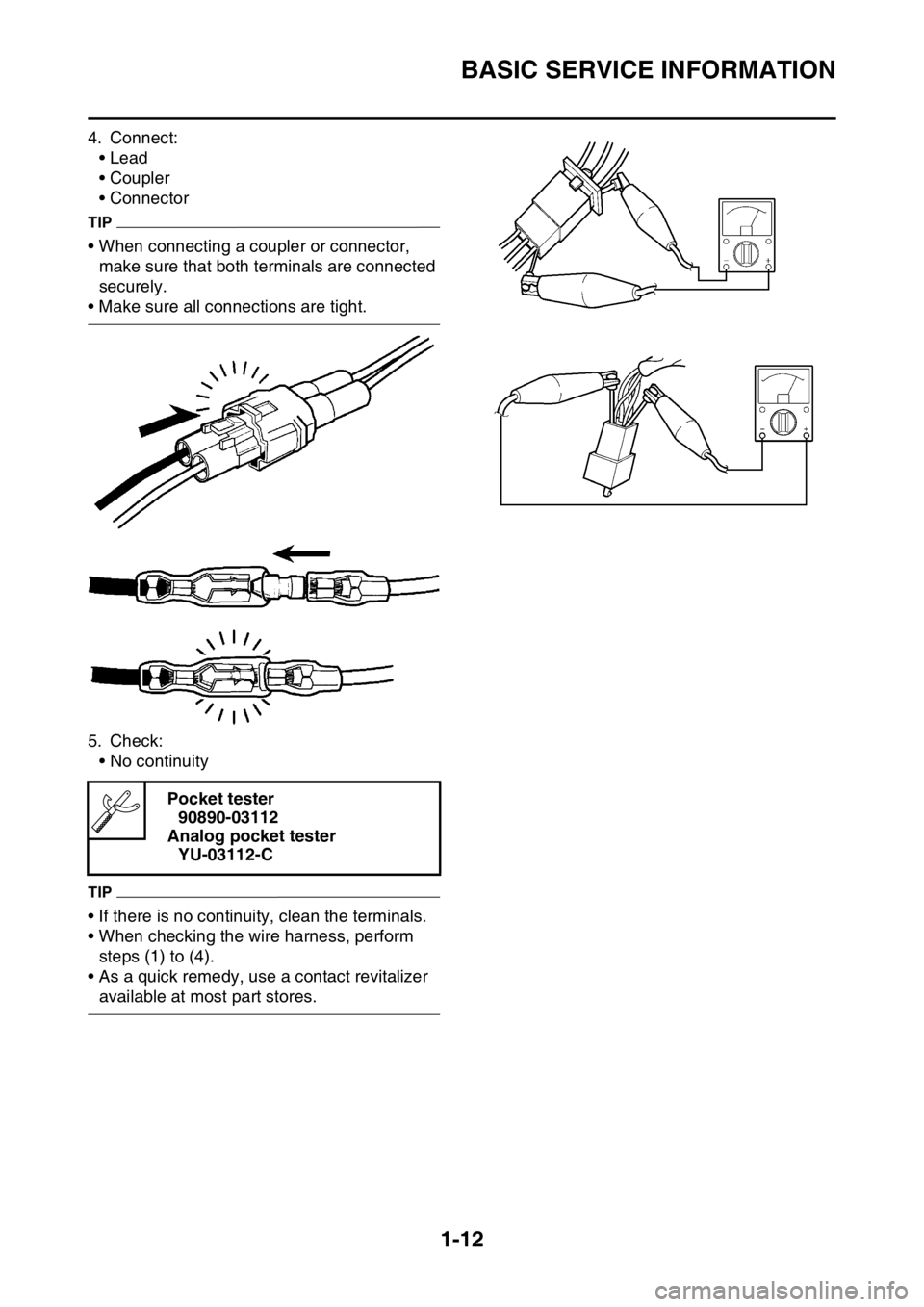
4. Connect:• Lead
• Coupler
• Connector
TIP
• When connecting a coupler or connector, make sure that both terminals are connected
securely.
• Make sure all connections are tight.
5. Check:• No continuity
TIP
• If there is no continuity, clean the terminals.
• When checking the wire harness, perform
steps (1) to (4).
• As a quick remedy, use a contact revitalizer
available at most part stores. Pocket tester
90890-03112
Analog pocket tester YU-03112-C
Page 27 of 426
SPECIAL TOOLS
1-13
EAS2GC1028
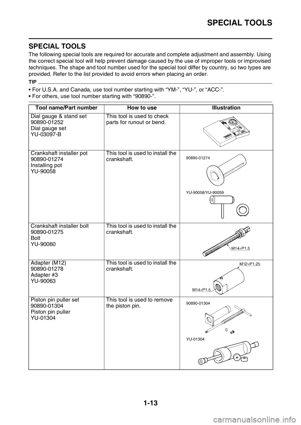
SPECIAL TOOLS
The following special tools are required for accurate and complete adjustment and assembly. Using
the correct special tool will help prevent damage ca used by the use of improper tools or improvised
techniques. The shape and tool number used for the special tool differ by country, so two types are
provided. Refer to the list provided to avoid errors when placing an order.
TIP
• For U.S.A. and Canada, use tool number starting with “YM-”, “YU-”, or “ACC-”.
• For others, use tool number starting with “90890-”.
Tool name/Part number How to use Illustration
Dial gauge & stand set
90890-01252
Dial gauge set
YU-03097-B This tool is used to check
parts for runout or bend.
Crankshaft installer pot
90890-01274
Installing pot
YU-90058 This tool is used to install the
crankshaft.
Crankshaft installer bolt
90890-01275
Bolt
YU-90060 This tool is used to install the
crankshaft.
Adapter (M12)
90890-01278
Adapter #3
YU-90063 This tool is used to install the
crankshaft.
Piston pin puller set
90890-01304
Piston pin puller
YU-01304 This tool is used to remove
the piston pin.