warning light YAMAHA XCITY 125 2012 Owners Manual
[x] Cancel search | Manufacturer: YAMAHA, Model Year: 2012, Model line: XCITY 125, Model: YAMAHA XCITY 125 2012Pages: 86, PDF Size: 7.38 MB
Page 6 of 86

TABLE OF CONTENTSSAFETY INFORMATION ..................1-1
Further safe-riding points ................1-5
DESCRIPTION ..................................2-1
Left view ..........................................2-1
Right view ........................................2-2
Controls and instruments.................2-3
INSTRUMENT AND CONTROL
FUNCTIONS.......................................3-1
Immobilizer system .........................3-1
Main switch/steering lock ................3-2
Indicator lights and warning light ....3-3
Speedometer ..................................3-4
Fuel gauge ......................................3-5
Coolant temperature gauge ............3-5
Multi-function display ......................3-5
Handlebar switches ........................3-8
Front brake lever ............................3-9
Rear brake lever .............................3-9
Fuel tank cap ................................3-10
Fuel ...............................................3-10
Catalytic converters ......................3-12
Seat ..............................................3-12
Storage compartments .................3-13
Windshield ....................................3-14
Adjusting the shock absorber
assemblies ................................3-15
Carrier ...........................................3-16
Luggage hook ...............................3-16
Sidestand ......................................3-16Ignition circuit cut-off system ........ 3-17
FOR YOUR SAFETY –
PRE-OPERATION CHECKS............. 4-1
OPERATION AND IMPORTANT
RIDING POINTS................................. 5-1
Starting the engine ......................... 5-1
Starting off ...................................... 5-2
Acceleration and deceleration ........ 5-3
Braking ........................................... 5-3
Tips for reducing fuel
consumption ............................... 5-4
Engine break-in .............................. 5-4
Parking ........................................... 5-5
PERIODIC MAINTENANCE AND
ADJUSTMENT................................... 6-1
Owner’s tool kit ............................... 6-2
Periodic maintenance chart for the
emission control system ............. 6-3
General maintenance and
lubrication chart .......................... 6-4
Removing and installing cowlings
and panels .................................. 6-8
Checking the spark plug ................. 6-9
Engine oil ..................................... 6-10
Final transmission oil .................... 6-13
Coolant ......................................... 6-14
Air filter and V-belt case air filter
elements ................................... 6-15Checking the throttle grip free
play ........................................... 6-16
Valve clearance ........................... 6-17
Tires ............................................. 6-17
Cast wheels ................................. 6-19
Front and rear brake lever free
play ........................................... 6-19
Checking the front and rear brake
pads .......................................... 6-20
Checking the brake fluid level ...... 6-21
Changing the brake fluid .............. 6-22
Checking and lubricating the
cables ....................................... 6-22
Checking and lubricating the
throttle grip and cable ............... 6-23
Lubricating the front and rear
brake levers .............................. 6-23
Checking and lubricating the
centerstand and sidestand ....... 6-23
Checking the front fork ................. 6-24
Checking the steering .................. 6-25
Checking the wheel bearings ....... 6-25
Battery ......................................... 6-25
Replacing the fuses ..................... 6-27
Replacing a headlight bulb .......... 6-28
Replacing a front turn signal light
bulb ........................................... 6-29
Replacing a tail/brake light bulb or
a rear turn signal light bulb ....... 6-30
Replacing the license plate light
bulb ........................................... 6-31U16PE3E0.book Page 1 Tuesday, June 19, 2012 5:17 PM
Page 18 of 86
INSTRUMENT AND CONTROL FUNCTIONS
3-2
3
●
Keep other immobilizer system
keys away from the main switch
as they may cause signal inter-
ference.
EAU10472
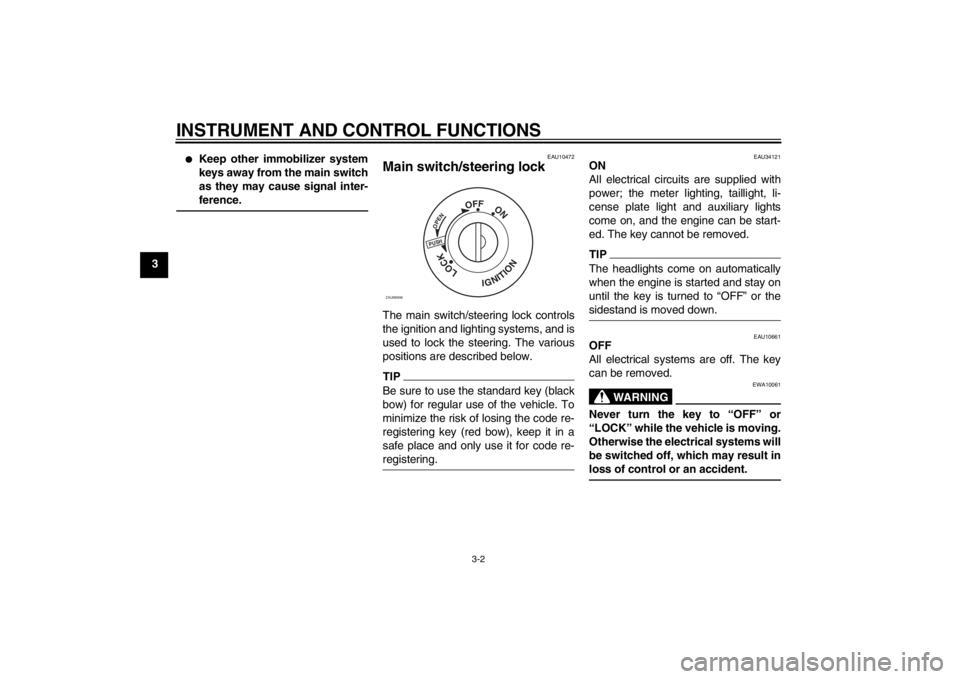
Main switch/steering lock The main switch/steering lock controls
the ignition and lighting systems, and is
used to lock the steering. The various
positions are described below.TIPBe sure to use the standard key (black
bow) for regular use of the vehicle. To
minimize the risk of losing the code re-
registering key (red bow), keep it in a
safe place and only use it for code re-
registering.
EAU34121
ON
All electrical circuits are supplied with
power; the meter lighting, taillight, li-
cense plate light and auxiliary lights
come on, and the engine can be start-
ed. The key cannot be removed.TIPThe headlights come on automatically
when the engine is started and stay on
until the key is turned to “OFF” or the
sidestand is moved down.
EAU10661
OFF
All electrical systems are off. The key
can be removed.
WARNING
EWA10061
Never turn the key to “OFF” or
“LOCK” while the vehicle is moving.
Otherwise the electrical systems will
be switched off, which may result in
loss of control or an accident.
PUSHOPEN
OFF
ON
LOCK
IGNITION
ZAUM0696
U16PE3E0.book Page 2 Tuesday, June 19, 2012 5:17 PM
Page 19 of 86
INSTRUMENT AND CONTROL FUNCTIONS
3-3
3
EAU10684
LOCK
The steering is locked, and all electrical
systems are off. The key can be re-
moved.
To lock the steering1. Turn the handlebars all the way to
the left.
2. Push the key in from the “OFF” po-
sition, and then turn it to “LOCK”
while still pushing it.
3. Remove the key.
To unlock the steeringPush the key in, and then turn it to
“OFF” while still pushing it.
EAU11006
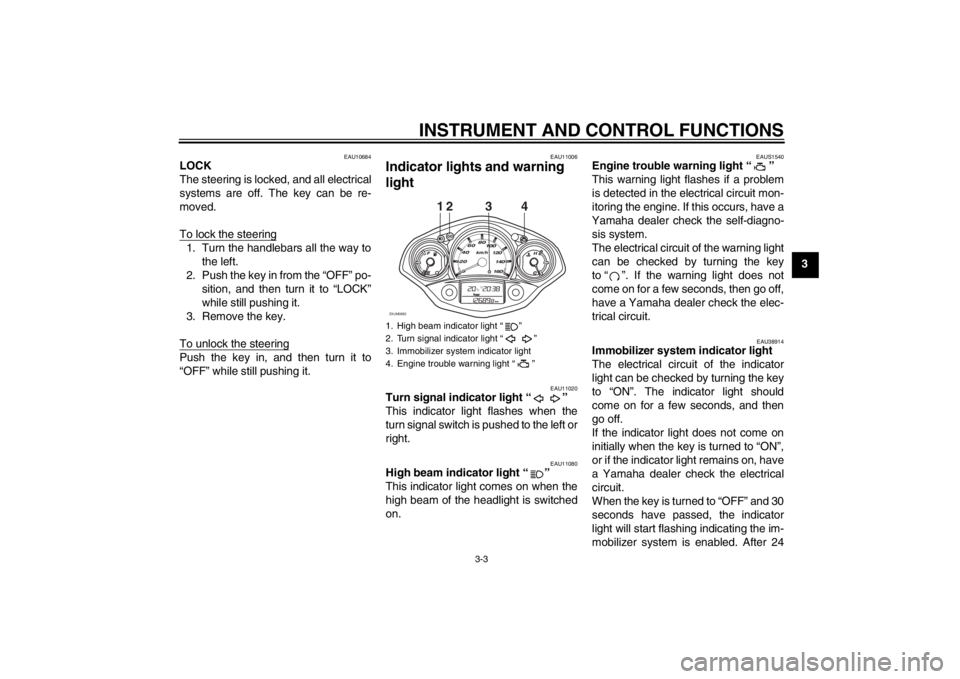
Indicator lights and warning
light
EAU11020
Turn signal indicator light “ ”
This indicator light flashes when the
turn signal switch is pushed to the left or
right.
EAU11080
High beam indicator light “ ”
This indicator light comes on when the
high beam of the headlight is switched
on.
EAUS1540
Engine trouble warning light “ ”
This warning light flashes if a problem
is detected in the electrical circuit mon-
itoring the engine. If this occurs, have a
Yamaha dealer check the self-diagno-
sis system.
The electrical circuit of the warning light
can be checked by turning the key
to “ ”. If the warning light does not
come on for a few seconds, then go off,
have a Yamaha dealer check the elec-
trical circuit.
EAU38914
Immobilizer system indicator light
The electrical circuit of the indicator
light can be checked by turning the key
to “ON”. The indicator light should
come on for a few seconds, and then
go off.
If the indicator light does not come on
initially when the key is turned to “ON”,
or if the indicator light remains on, have
a Yamaha dealer check the electrical
circuit.
When the key is turned to “OFF” and 30
seconds have passed, the indicator
light will start flashing indicating the im-
mobilizer system is enabled. After 24
1. High beam indicator light “ ”
2. Turn signal indicator light “ ”
3. Immobilizer system indicator light
4. Engine trouble warning light “ ”
12
ZAUM0882
34
U16PE3E0.book Page 3 Tuesday, June 19, 2012 5:17 PM
Page 21 of 86
INSTRUMENT AND CONTROL FUNCTIONS
3-5
3
EAUM1471
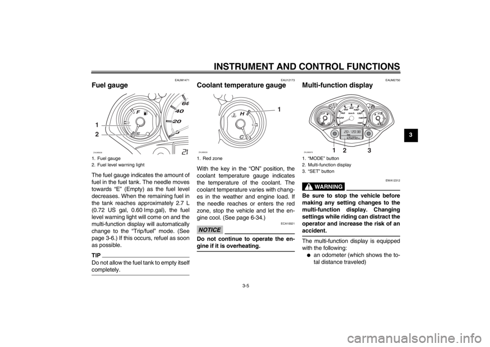
Fuel gauge The fuel gauge indicates the amount of
fuel in the fuel tank. The needle moves
towards “E” (Empty) as the fuel level
decreases. When the remaining fuel in
the tank reaches approximately 2.7 L
(0.72 US gal, 0.60 Imp.gal), the fuel
level warning light will come on and the
multi-function display will automatically
change to the “Trip/fuel” mode. (See
page 3-6.) If this occurs, refuel as soon
as possible.TIPDo not allow the fuel tank to empty itself
completely.
EAU12173
Coolant temperature gauge With the key in the “ON” position, the
coolant temperature gauge indicates
the temperature of the coolant. The
coolant temperature varies with chang-
es in the weather and engine load. If
the needle reaches or enters the red
zone, stop the vehicle and let the en-
gine cool. (See page 6-34.)NOTICE
ECA10021
Do not continue to operate the en-
gine if it is overheating.
EAUM2750
Multi-function display
WARNING
EWA12312
Be sure to stop the vehicle before
making any setting changes to the
multi-function display. Changing
settings while riding can distract the
operator and increase the risk of an
accident.The multi-function display is equipped
with the following:●
an odometer (which shows the to-
tal distance traveled)
1. Fuel gauge
2. Fuel level warning light1
2ZAUM0638
1. Red zone
1
ZAUM0639
1. “MODE” button
2. Multi-function display
3. “SET” button
1
2
3
ZAUM0878
U16PE3E0.book Page 5 Tuesday, June 19, 2012 5:17 PM
Page 22 of 86
INSTRUMENT AND CONTROL FUNCTIONS
3-6
3
●
two tripmeters (which show the
distance traveled since they were
last set to zero, the time passed
since the tripmeters were set to ze-
ro, and the average speed traveled
during this time)
●
a fuel reserve tripmeter (which
shows the distance traveled since
the fuel level warning light came
on)
●
a clock
●
an ambient temperature display
●
an oil change indicator (which
comes on when the engine oil
should be changed)
TIP●
For the UK, the distance traveled
is displayed in miles and the tem-
perature reading is displayed in °F.
●
For other countries, the distance
traveled is displayed in kilometers
and the temperature reading is dis-
played in °C.
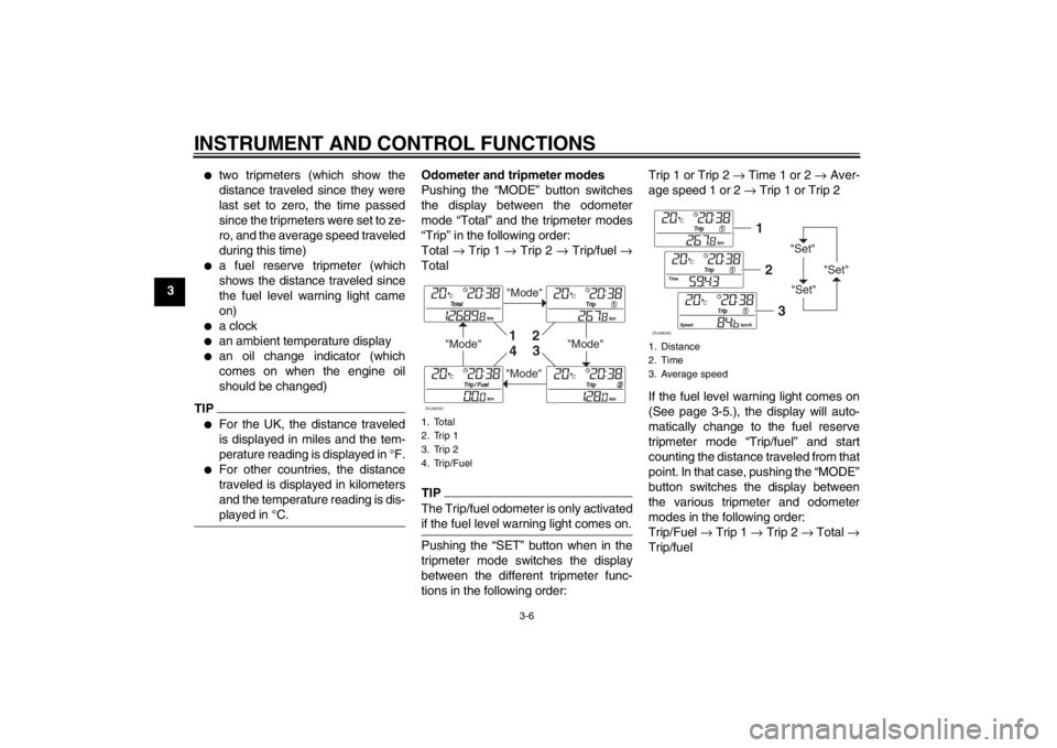
Odometer and tripmeter modes
Pushing the “MODE” button switches
the display between the odometer
mode “Total” and the tripmeter modes
“Trip” in the following order:
Total → Trip 1 → Trip 2 → Trip/fuel →
TotalTIPThe Trip/fuel odometer is only activated
if the fuel level warning light comes on.Pushing the “SET” button when in the
tripmeter mode switches the display
between the different tripmeter func-
tions in the following order:Trip 1 or Trip 2 → Time 1 or 2 → Aver-
age speed 1 or 2 → Trip 1 or Trip 2
If the fuel level warning light comes on
(See page 3-5.), the display will auto-
matically change to the fuel reserve
tripmeter mode “Trip/fuel” and start
counting the distance traveled from that
point. In that case, pushing the “MODE”
button switches the display between
the various tripmeter and odometer
modes in the following order:
Trip/Fuel → Trip 1 → Trip 2 → Total →
Trip/fuel1. Total
2. Trip 1
3. Trip 2
4. Trip/Fuel
"Mode"
"Mode"
"Mode"
"Mode"
1
2
3
4
ZAUM0391
1. Distance
2. Time
3. Average speed
"Set"
"Set""Set"
12
3
ZAUM0392
U16PE3E0.book Page 6 Tuesday, June 19, 2012 5:17 PM
Page 26 of 86
INSTRUMENT AND CONTROL FUNCTIONS
3-10
3
EAUM2161
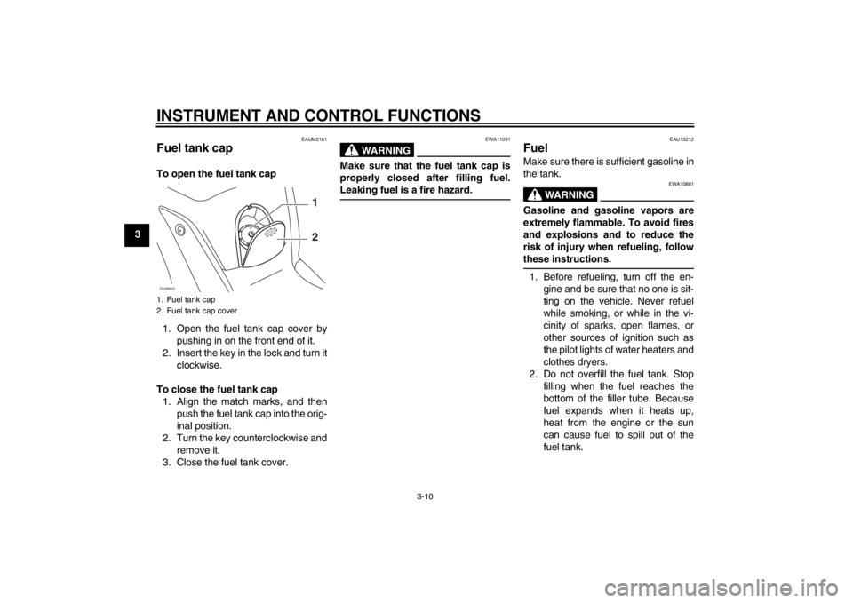
Fuel tank cap To open the fuel tank cap
1. Open the fuel tank cap cover by
pushing in on the front end of it.
2. Insert the key in the lock and turn it
clockwise.
To close the fuel tank cap
1. Align the match marks, and then
push the fuel tank cap into the orig-
inal position.
2. Turn the key counterclockwise and
remove it.
3. Close the fuel tank cover.
WARNING
EWA11091
Make sure that the fuel tank cap is
properly closed after filling fuel.
Leaking fuel is a fire hazard.
EAU13212
Fuel Make sure there is sufficient gasoline in
the tank.
WARNING
EWA10881
Gasoline and gasoline vapors are
extremely flammable. To avoid fires
and explosions and to reduce the
risk of injury when refueling, follow
these instructions.1. Before refueling, turn off the en-
gine and be sure that no one is sit-
ting on the vehicle. Never refuel
while smoking, or while in the vi-
cinity of sparks, open flames, or
other sources of ignition such as
the pilot lights of water heaters and
clothes dryers.
2. Do not overfill the fuel tank. Stop
filling when the fuel reaches the
bottom of the filler tube. Because
fuel expands when it heats up,
heat from the engine or the sun
can cause fuel to spill out of the
fuel tank.
1. Fuel tank cap
2. Fuel tank cap coverZAUM0643
1
2
U16PE3E0.book Page 10 Tuesday, June 19, 2012 5:17 PM
Page 33 of 86
INSTRUMENT AND CONTROL FUNCTIONS
3-17
3
WARNING
EWA10241
The vehicle must not be ridden with
the sidestand down, or if the side-
stand cannot be properly moved up
(or does not stay up), otherwise the
sidestand could contact the ground
and distract the operator, resulting
in a possible loss of control.
Yamaha’s ignition circuit cut-off
system has been designed to assist
the operator in fulfilling the respon-
sibility of raising the sidestand be-
fore starting off. Therefore, check
this system regularly and have a
Yamaha dealer repair it if it does not
function properly.
EAU45052
Ignition circuit cut-off system The ignition circuit cut-off system (com-
prising the sidestand switch and brake
light switches) has the following func-
tions.●
It prevents starting when the side-
stand is up, but neither brake is ap-
plied.
●
It prevents starting when either
brake is applied, but the sidestand
is still down.
●
It cuts the running engine when the
sidestand is moved down.
Periodically check the operation of the
ignition circuit cut-off system according
to the following procedure.
U16PE3E0.book Page 17 Tuesday, June 19, 2012 5:17 PM
Page 37 of 86
OPERATION AND IMPORTANT RIDING POINTS
5-1
5
EAU15951
Read the Owner’s Manual carefully to
become familiar with all controls. If
there is a control or function you do not
understand, ask your Yamaha dealer.
WARNING
EWA10271
Failure to familiarize yourself with
the controls can lead to loss of con-
trol, which could cause an accident
or injury.
EAU45310
TIPThis model is equipped with a lean an-
gle sensor to stop the engine in case of
a turnover. To start the engine after a
turnover, be sure to turn the main
switch to “OFF” and then to “ON”. Fail-
ing to do so will prevent the engine from
starting even though the engine will
crank when pushing the start switch.
EAUM2233
Starting the engine NOTICE
ECA10250
See page 5-4 for engine break-in in-
structions prior to operating the ve-
hicle for the first time.In order for the ignition circuit cut-off
system to enable starting, the side-
stand must be up.
See page 3-17 for more information.
1. Turn the key to “ON”.
The following warning lights and
indicator light should come on for a
few seconds, then go off.
●
Fuel level warning light
●
Engine trouble warning light
●
Immobilizer system indicator
light
NOTICE
ECA11833
If a warning or indicator light does
not come on initially when the key is
turned to “ON”, or if a warning or in-
dicator light remains on, see page
3-3 for the corresponding warning
and indicator light circuit check.2. Close the throttle completely.
U16PE3E0.book Page 1 Tuesday, June 19, 2012 5:17 PM
Page 55 of 86
PERIODIC MAINTENANCE AND ADJUSTMENT
6-14
6
EAU20070
Coolant The coolant level should be checked
before each ride. In addition, the cool-
ant must be changed at the intervals
specified in the periodic maintenance
and lubrication chart.
EAUM2102
To check the coolant level
1. Place the vehicle on a level sur-
face and hold it in an upright posi-
tion.TIP●
The coolant level must be checked
on a cold engine since the level
varies with engine temperature.
●
Make sure that the vehicle is posi-
tioned straight up when checking
the coolant level. A slight tilt to the
side can result in a false reading.
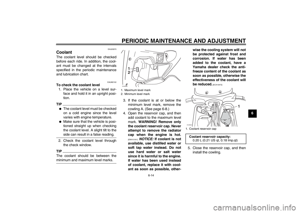
2. Check the coolant level through
the check window.TIPThe coolant should be between the
minimum and maximum level marks.
3. If the coolant is at or below the
minimum level mark, remove the
cowling A. (See page 6-8.)
4. Open the reservoir cap, and then
add coolant to the maximum level
mark. WARNING! Remove only
the coolant reservoir cap. Never
attempt to remove the radiator
cap when the engine is hot.
[EWA15161]
NOTICE: If coolant is not
available, use distilled water or
soft tap water instead. Do not
use hard water or salt water
since it is harmful to the engine.
If water has been used instead
of coolant, replace it with cool-
ant as soon as possible, other-wise the cooling system will not
be protected against frost and
corrosion. If water has been
added to the coolant, have a
Yamaha dealer check the anti-
freeze content of the coolant as
soon as possible, otherwise the
effectiveness of the coolant will
be reduced.
[ECA10472]
5. Close the reservoir cap, and then
install the cowling.
1. Maximum level mark
2. Minimum level mark
1
2
ZAUM0660
1. Coolant reservoir cap
Coolant reservoir capacity:
0.20 L (0.21 US qt, 0.18 Imp.qt)
1
ZAUM0661
U16PE3E0.book Page 14 Tuesday, June 19, 2012 5:17 PM
Page 68 of 86
PERIODIC MAINTENANCE AND ADJUSTMENT
6-27
6
EAU23526
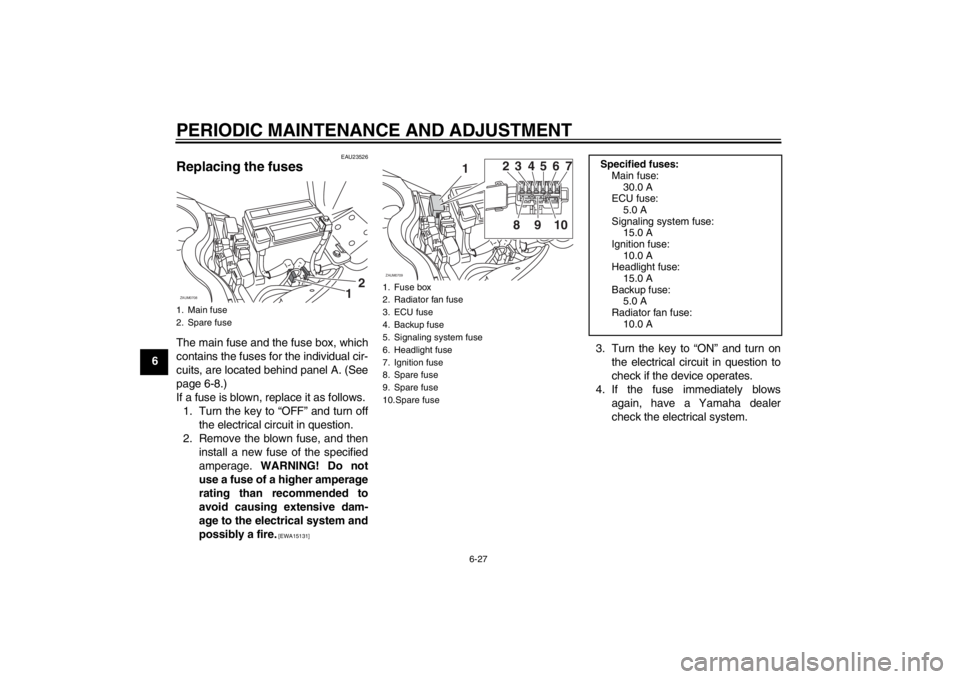
Replacing the fuses The main fuse and the fuse box, which
contains the fuses for the individual cir-
cuits, are located behind panel A. (See
page 6-8.)
If a fuse is blown, replace it as follows.
1. Turn the key to “OFF” and turn off
the electrical circuit in question.
2. Remove the blown fuse, and then
install a new fuse of the specified
amperage. WARNING! Do not
use a fuse of a higher amperage
rating than recommended to
avoid causing extensive dam-
age to the electrical system and
possibly a fire.
[EWA15131]
3. Turn the key to “ON” and turn on
the electrical circuit in question to
check if the device operates.
4. If the fuse immediately blows
again, have a Yamaha dealer
check the electrical system.
1. Main fuse
2. Spare fuse
12
ZAUM0708
1. Fuse box
2. Radiator fan fuse
3. ECU fuse
4. Backup fuse
5. Signaling system fuse
6. Headlight fuse
7. Ignition fuse
8. Spare fuse
9. Spare fuse
10.Spare fuse
1
ZAUM0709
23
8910 456 7
Specified fuses:
Main fuse:
30.0 A
ECU fuse:
5.0 A
Signaling system fuse:
15.0 A
Ignition fuse:
10.0 A
Headlight fuse:
15.0 A
Backup fuse:
5.0 A
Radiator fan fuse:
10.0 A
U16PE3E0.book Page 27 Tuesday, June 19, 2012 5:17 PM