check engine YAMAHA XENTER 150 2012 Owners Manual
[x] Cancel search | Manufacturer: YAMAHA, Model Year: 2012, Model line: XENTER 150, Model: YAMAHA XENTER 150 2012Pages: 84, PDF Size: 1.33 MB
Page 6 of 84
TABLE OF CONTENTSSAFETY INFORMATION .................... 1-1
Further safe-riding points ................. 1-5
DESCRIPTION .................................... 2-1
Left view ........................................... 2-1
Right view ......................................... 2-2
Controls and instruments ................. 2-3
INSTRUMENT AND CONTROL FUNC-
TIONS .................................................. 3-1
Main switch/steering lock ................. 3-1
Indicator lights and warning lights .... 3-2
Multi-function display ........................ 3-3
Handlebar switches .......................... 3-7
Front brake lever .............................. 3-7
Rear brake lever ............................... 3-8
Fuel tank cap .................................... 3-8
Fuel .................................................. 3-9
Catalytic converter ......................... 3-10
Seat ................................................ 3-11
Passenger footrest ......................... 3-12
Front storage compartment ............ 3-12
Rear storage compartment ............ 3-13
Shock absorber assembly .............. 3-13
Carrier ............................................ 3-14
Luggage holder .............................. 3-14
FOR YOUR SAFETY - PRE-OPERATION
CHECKS ............................................. 4-1OPERATION AND IMPORTANT RIDING
POINTS ............................................... 5-1
Starting the engine ........................... 5-1
Starting off ........................................ 5-2
Acceleration and deceleration .......... 5-2
Braking ............................................. 5-2
Tips for reducing fuel consumption .. 5-3
Engine break-in ................................ 5-3
Parking ............................................. 5-4
PERIODIC MAINTENANCE AND
ADJUSTMENT .................................... 6-1
Owner’s tool kit ................................. 6-2
Periodic maintenance chart for the
emission control system ................... 6-3
General maintenance and lubrication
chart .............................................. 6-4
Removing and installing the cowling
and panels .................................... 6-7
Checking the spark plug ................... 6-9
Engine oil and oil strainer ............... 6-10
Final transmission oil ...................... 6-12
Coolant ........................................... 6-13
Air fi lter and V-belt case air fi lter
elements ..................................... 6-15
Checking the engine idling speed .. 6-16
Checking the throttle grip free
play ............................................. 6-16
Valve clearance .............................. 6-17
Tires ............................................... 6-17
Cast wheels .................................... 6-19Checking the front brake lever free
play ............................................. 6-19
Adjusting the rear brake lever free
play ............................................. 6-19
Checking the front brake pads and
rear brake shoes ......................... 6-20
Checking the brake fl uid level ........ 6-21
Changing the brake fl uid ................ 6-22
Checking and lubricating the
cables ......................................... 6-22
Checking and lubricating the throttle
grip and cable ............................. 6-23
Lubricating the front and rear brake
levers .......................................... 6-23
Checking and lubricating the
centerstand ................................. 6-23
Checking the front fork ................... 6-24
Checking the steering .................... 6-25
Checking the wheel bearings ......... 6-25
Battery ............................................ 6-25
Replacing the fuses ........................ 6-27
Replacing a headlight bulb ............. 6-28
Tail/brake light ................................ 6-29
Replacing a front turn signal light
bulb ............................................. 6-29
Replacing an auxiliary light bulb ..... 6-30
Replacing a rear turn signal light
bulb ............................................. 6-31
License plate light .......................... 6-31
Troubleshooting ............................. 6-32
Troubleshooting charts ................... 6-33
52S-F8199-E0_CS.indd 652S-F8199-E0_CS.indd 6
2011/11/16 13:06:592011/11/16 13:06:59
Process BlackProcess Black
Page 10 of 84

1
2
3
4
5
6
7
8
9
1-3
Q
SAFETY INFORMATION●
Do not run engine in poorly ven-
tilated or partially enclosed areas
such as barns, garages, or car-
ports.
●
Do not run engine outdoors
where engine exhaust can be
drawn into a building through
openings such as windows and
doors.
Loading
Adding accessories or cargo to your
scooter can adversely affect stability
and handling if the weight distribution
of the scooter is changed. To avoid
the possibility of an accident, use ex-
treme caution when adding cargo or
accessories to your scooter. Use extra
care when riding a scooter that has
added cargo or accessories. Here,
along with the information about ac-
cessories below, are some general
guidelines to follow if loading cargo to
your scooter:
The total weight of the operator,
passenger, accessories and cargo
must not exceed the maximum load
limit. Operation of an overloaded
vehicle could cause an accident.
Maximum load:
179 kg (395 lb)When loading within this weight limit,
keep the following in mind:●
Cargo and accessory weight
should be kept as low and close
to the scooter as possible. Se-
curely pack your heaviest items
as close to the center of the ve-
hicle as possible and make sure
to distribute the weight as evenly
as possible on both sides of the
scooter to minimize imbalance or
instability.
●
Shifting weights can create a
sudden imbalance. Make sure
that accessories and cargo are
securely attached to the scooter
before riding. Check accessory
mounts and cargo restraints fre-
quently.
• Properly adjust the suspen-
sion for your load (suspension-
adjustable models only), and
check the condition and pres-
sure of your tires.
• Never attach any large or heavy items to the handlebar,
front fork, or front fender. Such
items can create unstable
handling or a slow steering re-
sponse.
●
This vehicle is not designed to
pull a trailer or to be attached
to a sidecar.
Genuine Yamaha Accessories
Choosing accessories for your vehicle
is an important decision. Genuine
Yamaha accessories, which are avail-
able only from a Yamaha dealer, have
been designed, tested, and approved
by Yamaha for use on your vehicle.
Many companies with no connection
to Yamaha manufacture parts and ac-
cessories or offer other modifications
for Yamaha vehicles. Yamaha is not
in a position to test the products that
these aftermarket companies pro-
duce. Therefore, Yamaha can neither
endorse nor recommend the use of
accessories not sold by Yamaha or
modifications not specifically recom-
mended by Yamaha, even if sold and
installed by a Yamaha dealer.
52S-F8199-E0_CS.indd 1-352S-F8199-E0_CS.indd 1-3
2011/11/16 13:06:592011/11/16 13:06:59
Process BlackProcess Black
Page 18 of 84
1
2
3
4
5
6
7
8
9
3-2
EAU1044E
INSTRUMENT AND CONTROL FUNCTIONS
EAU49391
Indicator lights and warning
lights
SELECT
RESET
ODOOIL
TRI P 1 BE
L
T TRIP 2
OIL CHANGECLOOK
OUT TEM
P
3
24
1 1
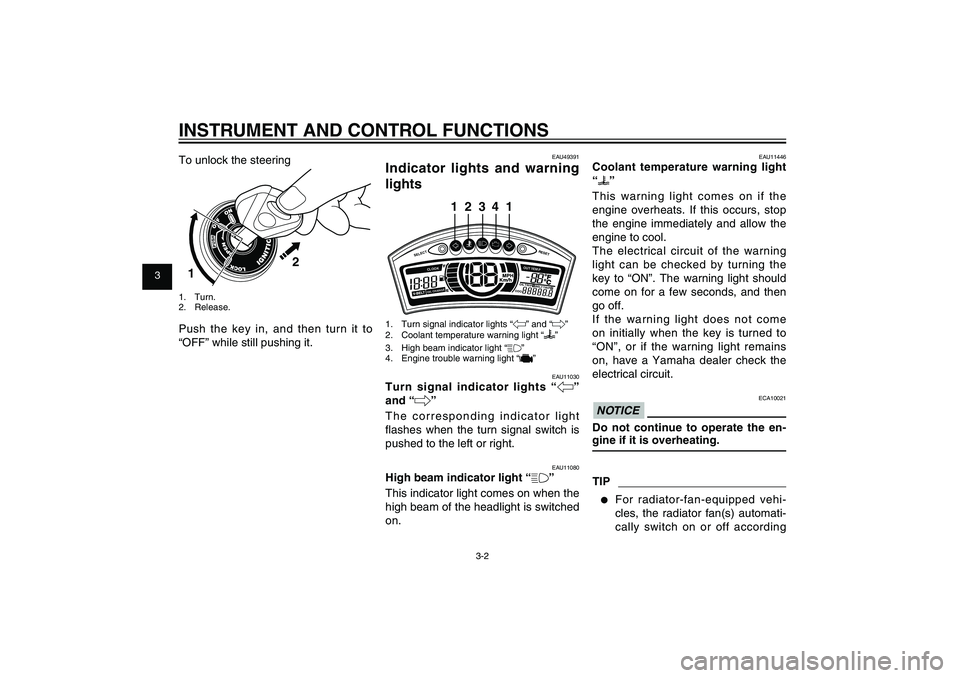
1. Turn signal indicator lights “4” and “6”
2. Coolant temperature warning light “
”
3. High beam indicator light “&”
4. Engine trouble warning light “
”
EAU11030
Turn signal indicator lights “4”
and “6”
The corresponding indicator light
fl ashes when the turn signal switch is
pushed to the left or right.
EAU11080
High beam indicator light “&”
This indicator light comes on when the
high beam of the headlight is switched
on. To unlock the steering
2
1
1. Turn.
2. Release.Push the key in, and then turn it to
“OFF” while still pushing it.
EAU11446
Coolant temperature warning light
“
”
This warning light comes on if the
engine overheats. If this occurs, stop
the engine immediately and allow the
engine to cool.
The electrical circuit of the warning
light can be checked by turning the
key to “ON”. The warning light should
come on for a few seconds, and then
go off.
If the warning light does not come
on initially when the key is turned to
“ON”, or if the warning light remains
on, have a Yamaha dealer check the
electrical circuit.
ECA10021
NOTICEDo not continue to operate the en-
gine if it is overheating.TIP● For radiator-fan-equipped vehi-
cles, the radiator fan(s) automati-
cally switch on or off according
52S-F8199-E0_CS.indd 3-252S-F8199-E0_CS.indd 3-2
2011/11/16 13:07:002011/11/16 13:07:00
Process BlackProcess Black
Page 19 of 84
1
2
3
4
5
6
7
8
9
3-3
EAU1044E
INSTRUMENT AND CONTROL FUNCTIONS
to the coolant temperature in the
radiator.
● If the engine overheats, see page
6-34 for further instructions.
EAUT1934
Engine trouble warning light “
”
This warning light fl ashes or stays on
if an electrical circuit monitoring the
engine is not working correctly. If this
occurs, have a Yamaha dealer check
the self-diagnosis system.
The electrical circuit of the warning
light can be checked by turning the
key to “ON”. The warning light should
come on for a few seconds, and then
go off.
If the warning light does not come
on initially when the key is turned to
“ON”, or if the warning light remains
on, have a Yamaha dealer check the
electrical circuit.
EAUT3721
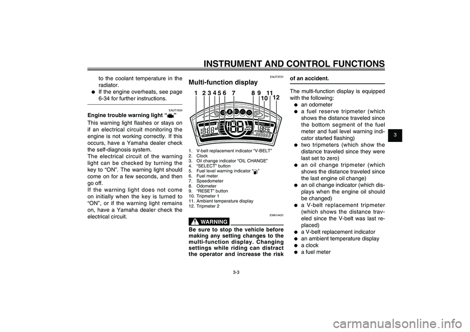
Multi-function display
SELECT
RESET
ODOOIL
TRI P 1 BE
L
T TRIP 2
OIL CHANGECLOOK
OUT TEM
P
12
34
56
789
1012 111. V-belt replacement indicator “V-BELT”
2. Clock
3. Oil change indicator “OIL CHANGE”
4. “SELECT” button
5. Fuel level warning indicator “
”
6. Fuel meter
7. Speedometer
8. Odometer
9. “RESET” button
10. Tripmeter 1
11. Ambient temperature display
12. Tripmeter 2
EWA14431
WARNING
Be sure to stop the vehicle before
making any setting changes to the
multi-function display. Changing
settings while riding can distract
the operator and increase the risk
of an accident.
The multi-function display is equipped
with the following:● an odometer● a fuel reserve tripmeter (which
shows the distance traveled since
the bottom segment of the fuel
meter and fuel level warning indi-
cator started fl ashing)● two tripmeters (which show the
distance traveled since they were
last set to zero)● an oil change tripmeter (which
shows the distance traveled since
the last engine oil change)● an oil change indicator (which dis-
plays when the engine oil should
be changed)● a V-belt replacement tripmeter
(which shows the distance trav-
eled since the V-belt was last re-
placed)● a V-belt replacement indicator● an ambient temperature display● a clock● a fuel meter
52S-F8199-E0_CS.indd 3-352S-F8199-E0_CS.indd 3-3
2011/11/16 13:07:002011/11/16 13:07:00
Process BlackProcess Black
Page 21 of 84
1
2
3
4
5
6
7
8
9
3-5
EAU1044E
INSTRUMENT AND CONTROL FUNCTIONS
Oil change tripmeter
To reset the oil change tripmeter, se-
lect it by pushing the “SELECT” button
until “OIL CHANGE” and “OIL TRIP”
are displayed, and then push the “RE-
SET” button for at least 3 seconds.
After resetting, “OIL CHANGE” will
disappear.
Push the “SELECT” button again to
start the oil change tripmeter; the
display changes to V-belt tripmeter
mode.
Oil change indicator “OIL CHANGE”
This indicator will display at the initial
1000 km (625 mi), then at every 6000
km (3750 mi) thereafter to indicate
that the engine oil should be changed.
After changing the engine oil, reset
the oil change tripmeter.
If the engine oil is changed before
the oil change indicator displays
(i.e., before the periodic oil change
interval has been reached), the oil
change tripmeter must be reset after
the oil change for the next periodic oil
change to be indicated at the correct
time.
TIP● If the oil change tripmeter is reset
before the initial 1000 km (625
mi), the next periodic oil change
interval will be at every 6000 km
(3750 mi) thereafter.● If the oil change tripmeter in-
dicates “-----”, have a Yamaha
dealer check the multi-function
display, as it may be faulty.
V-belt replacement tripmeter
To reset the V-belt tripmeter, select it
by pushing the “SELECT” button until
“V-BELT” and “BELT TRIP” are dis-
played, and then push the “RESET”
button for at least 3 seconds. After
resetting, “V-BELT” will disappear.
Push the “SELECT” button again to
start the V-belt tripmeter; the display
changes to ODO mode.
V-belt change indicator “V-BELT”
This indicator comes on at every
20000 km (12500 mi) to indicate that
the V-belt should be replaced.
After replacing the V-belt, reset the V-
belt tripmeter.
If the V-belt is replaced before the
V-belt indicator comes on (i.e., be-
fore the periodic V-belt replacement
interval has been reached), the V-belt
tripmeter must be reset after replacing
the V-belt for the next periodic V-belt
replacement to be indicated at the cor-
rect time.TIPIf the V-belt change indicator displays
“-----”, have a Yamaha dealer check
the multi-function display, as it may be
faulty.
Ambient temperature display “OUT
TEMP”
This display shows the ambient tem-
perature from -10 °C to 40 °C in 1
°C increments. The temperature dis-
played may vary from the ambient
temperature.TIP● If the ambient temperature falls
52S-F8199-E0_CS.indd 3-552S-F8199-E0_CS.indd 3-5
2011/11/16 13:07:002011/11/16 13:07:00
Process BlackProcess Black
Page 32 of 84
1
2
3
4
5
6
7
8
9
4-2
EAU15582
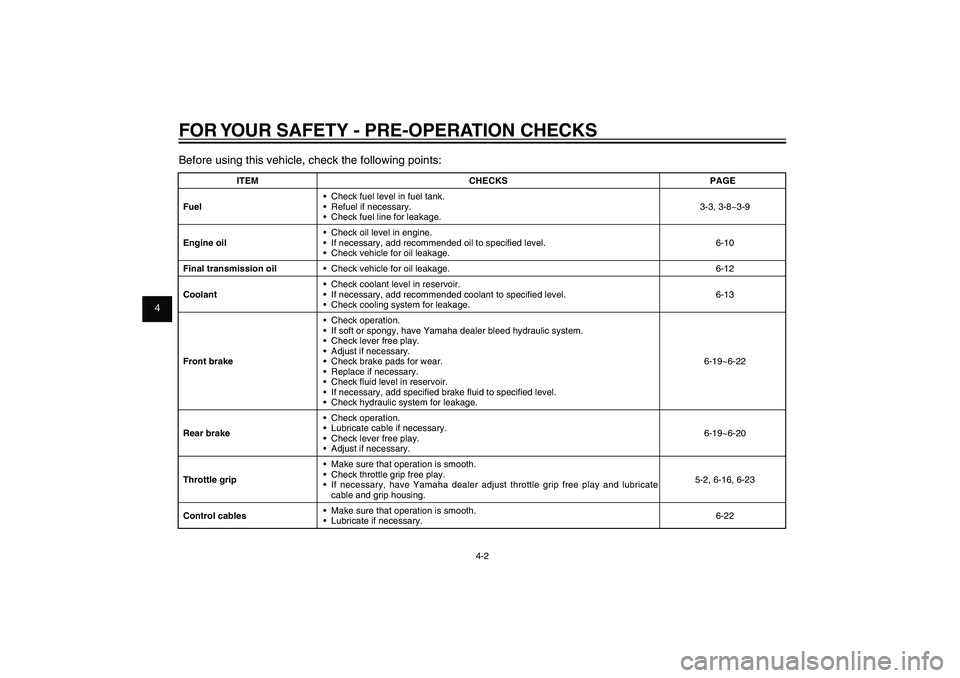
FOR YOUR SAFETY - PRE-OPERATION CHECKSBefore using this vehicle, check the following points:
ITEM CHECKS PAGE
Fuel• Check fuel level in fuel tank.
• Refuel if necessary.
• Check fuel line for leakage.3-3, 3-8~3-9
Engine oil• Check oil level in engine.
• If necessary, add recommended oil to specifi ed level.
• Check vehicle for oil leakage.6-10
Final transmission oil• Check vehicle for oil leakage. 6-12
Coolant• Check coolant level in reservoir.
• If necessary, add recommended coolant to specifi ed level.
• Check cooling system for leakage.6-13
Front brake• Check operation.
• If soft or spongy, have Yamaha dealer bleed hydraulic system.
• Check lever free play.
• Adjust if necessary.
• Check brake pads for wear.
• Replace if necessary.
• Check fl uid level in reservoir.
• If necessary, add specifi ed brake fl uid to specifi ed level.
• Check hydraulic system for leakage.6-19~6-22
Rear brake• Check operation.
• Lubricate cable if necessary.
• Check lever free play.
• Adjust if necessary.6-19~6-20
Throttle grip• Make sure that operation is smooth.
• Check throttle grip free play.
• If necessary, have Yamaha dealer adjust throttle grip free play and lubricate
cable and grip housing.5-2, 6-16, 6-23
Control cables• Make sure that operation is smooth.
• Lubricate if necessary.6-22
52S-F8199-E0_CS.indd 4-252S-F8199-E0_CS.indd 4-2
2011/11/16 13:07:002011/11/16 13:07:00
Process BlackProcess Black
Page 34 of 84

1
2
3
4
5
6
7
8
9
5-1
EAU15943
OPERATION AND IMPORTANT RIDING POINTS
EAU15943
OPERATION AND IMPORTANT RIDING POINTS
EAU15951
Read the Owner’s Manual carefully
to become familiar with all controls.
If there is a control or function you
do not understand, ask your Yamaha
dealer.
EWA10271
WARNING
Failure to familiarize yourself with
the controls can lead to loss of
control, which could cause an ac-
cident or injury.
EAU45310
TIPThis model is equipped with a lean
angle sensor to stop the engine in
case of a turnover. To start the en-
gine after a turnover, be sure to turn
the main switch to “OFF” and then to
“ON”. Failing to do so will prevent the
engine from starting even though the
engine will crank when pushing the
start switch.
EAUT3680
Starting the engine
ECA10250
NOTICESee page 5-3 for engine break-in
instructions prior to operating the
vehicle for the � rst time.
1. Turn the key to “ON”.
The engine trouble warning light
and coolant temperature warning
light should come on for a few
seconds, then go off.
NOTICE:
If
a warning light does not go off,
have a Yamaha dealer check its
electrical circuit.
[ECAT1170]
2. Close the throttle completely.
3. Start the engine by pushing the
start switch while applying the
front or rear brake.
NOTICE:
For
maximum engine life, never ac-
celerate hard when the engine
is cold!
[ECA11041]
If the engine does not start, re-
lease the start switch, wait a few
seconds, and then try again.
Each starting attempt should be
as short as possible to preserve the battery. Do not crank the en-
gine more than 10 seconds on
any one attempt.
52S-F8199-E0_CS.indd 5-152S-F8199-E0_CS.indd 5-1
2011/11/16 13:07:002011/11/16 13:07:00
Process BlackProcess Black
Page 35 of 84

1
2
3
4
5
6
7
8
9
5-2
EAU15943
OPERATION AND IMPORTANT RIDING POINTS
EAU16780
Acceleration and decelera-
tion
(a) (b)
The speed can be adjusted by open-
ing and closing the throttle. To in-
crease the speed, turn the throttle grip
in direction (a). To reduce the speed,
turn the throttle grip in direction (b).
EAU16793
Braking
EWA10300
WARNING
● Avoid braking hard or sud-
denly (especially when leaning
over to one side), otherwise the
scooter may skid or overturn.● Railroad crossings, streetcar
rails, iron plates on road con-
struction sites, and manhole
covers become extremely slip-
pery when wet. Therefore, slow
down when approaching such
areas and cross them with cau-
tion.● Keep in mind that braking on
a wet road is much more diffi-
cult.● Ride slowly down a hill, as
braking downhill can be very
dif� cult.
1. Close the throttle completely.
2. Apply both front and rear brakes
simultaneously while gradually
increasing the pressure.
EAU16761
Starting offTIPBefore starting off, allow the engine to
warm up.
1. While pulling the rear brake lever
with your left hand and holding
the grab bar with your right hand,
push the scooter off the center-
stand.
2. Sit astride the seat, and then ad-
just the rear view mirrors.
3. Switch the turn signals on.
4. Check for oncoming traffic, and
then slowly turn the throttle grip
(on the right) in order to take off.
5. Switch the turn signals off.
52S-F8199-E0_CS.indd 5-252S-F8199-E0_CS.indd 5-2
2011/11/16 13:07:002011/11/16 13:07:00
Process BlackProcess Black
Page 36 of 84
1
2
3
4
5
6
7
8
9
5-3
EAU15943
OPERATION AND IMPORTANT RIDING POINTS
EAU16820
Tips for reducing fuel con-
sumptionFuel consumption depends largely on
your riding style. Consider the follow-
ing tips to reduce fuel consumption:● Avoid high engine speeds during
acceleration.● Avoid high engine speeds with no
load on the engine.● Turn the engine off instead of let-
ting it idle for an extended length
of time (e.g., in traffic jams, at
traffic lights or at railroad cross-
ings).
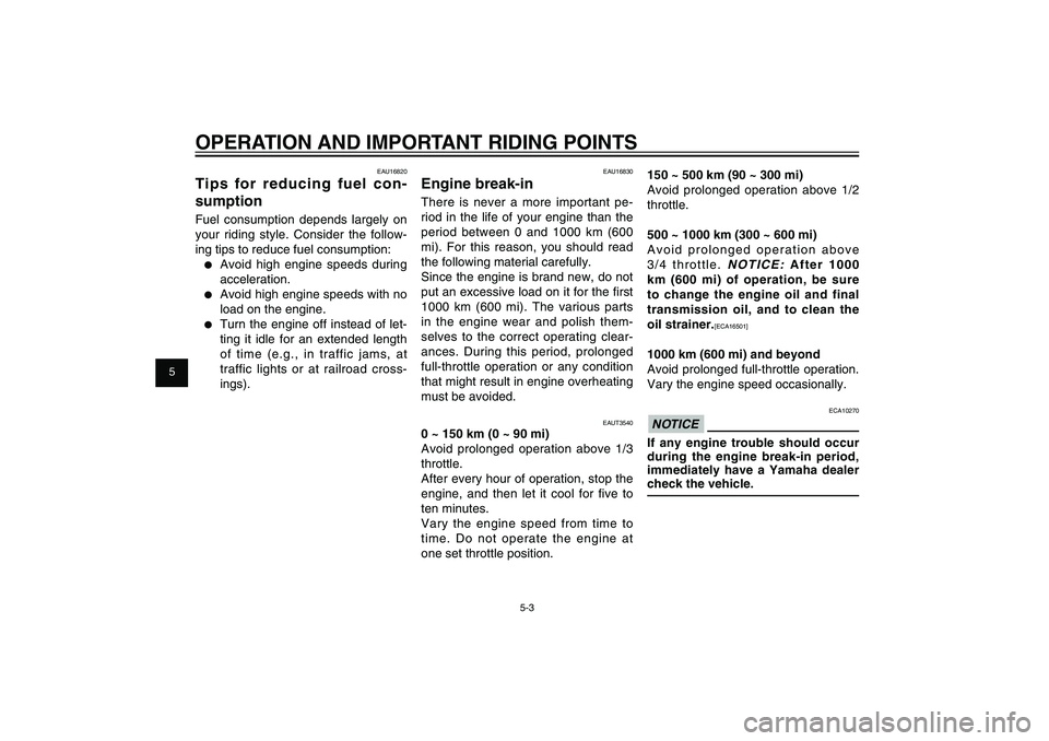
EAU16830
Engine break-inThere is never a more important pe-
riod in the life of your engine than the
period between 0 and 1000 km (600
mi). For this reason, you should read
the following material carefully.
Since the engine is brand new, do not
put an excessive load on it for the fi rst
1000 km (600 mi). The various parts
in the engine wear and polish them-
selves to the correct operating clear-
ances. During this period, prolonged
full-throttle operation or any condition
that might result in engine overheating
must be avoided.
EAUT3540
0 ~ 150 km (0 ~ 90 mi)
Avoid prolonged operation above 1/3
throttle.
After every hour of operation, stop the
engine, and then let it cool for fi ve to
ten minutes.
Vary the engine speed from time to
time. Do not operate the engine at
one set throttle position.
150 ~ 500 km (90 ~ 300 mi)
Avoid prolonged operation above 1/2
throttle.
500 ~ 1000 km (300 ~ 600 mi)
Avoid prolonged operation above
3/4 throttle.
NOTICE:
After 1000
km (600 mi) of operation, be sure
to change the engine oil and final
transmission oil, and to clean the
oil strainer.
[ECA16501]
1000 km (600 mi) and beyond
Avoid prolonged full-throttle operation.
Vary the engine speed occasionally.
ECA10270
NOTICEIf any engine trouble should occur
during the engine break-in period,
immediately have a Yamaha dealer
check the vehicle.
52S-F8199-E0_CS.indd 5-352S-F8199-E0_CS.indd 5-3
2011/11/16 13:07:002011/11/16 13:07:00
Process BlackProcess Black
Page 40 of 84

1
2
3
4
5
6
7
8
9
6-3
EAU1722A
PERIODIC MAINTENANCE AND ADJUSTMENT
EAU46871
TIP● The annual checks must be performed every year, except if a kilometer-based maintenance, or for the UK, a
mileage-based maintenance, is performed instead.● From 30000 km (17500 mi), repeat the maintenance intervals starting from 6000 km (3500 mi).● Items marked with an asterisk should be performed by a Yamaha dealer as they require special tools, data and
technical skills.
EAU46920
Periodic maintenance chart for the emission control systemNO. ITEM CHECK OR MAINTENANCE JOBODOMETER READING
ANNUAL
CHECK
1000 km
(600 mi)6000 km
(3500 mi)
12000 km
(7000 mi)18000 km
(10500 mi)24000 km
(14000 mi)
1 * Fuel line• Check fuel hoses for cracks or damage.
√√√√ √
2 Spark plug• Check condition.
• Clean and regap.√√
• Replace.
√√
3 * Valves• Check valve clearance.
• Adjust.√√√√
4 * Fuel injection• Check engine idle speed.
√√√√√ √
5*Muffler and exhaust
pipe• Check the screw clamp(s) for looseness.
√√√√√
52S-F8199-E0_CS.indd 6-352S-F8199-E0_CS.indd 6-3
2011/11/16 13:07:012011/11/16 13:07:01
Process BlackProcess Black