battery YAMAHA XENTER 150 2012 Owners Manual
[x] Cancel search | Manufacturer: YAMAHA, Model Year: 2012, Model line: XENTER 150, Model: YAMAHA XENTER 150 2012Pages: 84, PDF Size: 1.33 MB
Page 6 of 84
TABLE OF CONTENTSSAFETY INFORMATION .................... 1-1
Further safe-riding points ................. 1-5
DESCRIPTION .................................... 2-1
Left view ........................................... 2-1
Right view ......................................... 2-2
Controls and instruments ................. 2-3
INSTRUMENT AND CONTROL FUNC-
TIONS .................................................. 3-1
Main switch/steering lock ................. 3-1
Indicator lights and warning lights .... 3-2
Multi-function display ........................ 3-3
Handlebar switches .......................... 3-7
Front brake lever .............................. 3-7
Rear brake lever ............................... 3-8
Fuel tank cap .................................... 3-8
Fuel .................................................. 3-9
Catalytic converter ......................... 3-10
Seat ................................................ 3-11
Passenger footrest ......................... 3-12
Front storage compartment ............ 3-12
Rear storage compartment ............ 3-13
Shock absorber assembly .............. 3-13
Carrier ............................................ 3-14
Luggage holder .............................. 3-14
FOR YOUR SAFETY - PRE-OPERATION
CHECKS ............................................. 4-1OPERATION AND IMPORTANT RIDING
POINTS ............................................... 5-1
Starting the engine ........................... 5-1
Starting off ........................................ 5-2
Acceleration and deceleration .......... 5-2
Braking ............................................. 5-2
Tips for reducing fuel consumption .. 5-3
Engine break-in ................................ 5-3
Parking ............................................. 5-4
PERIODIC MAINTENANCE AND
ADJUSTMENT .................................... 6-1
Owner’s tool kit ................................. 6-2
Periodic maintenance chart for the
emission control system ................... 6-3
General maintenance and lubrication
chart .............................................. 6-4
Removing and installing the cowling
and panels .................................... 6-7
Checking the spark plug ................... 6-9
Engine oil and oil strainer ............... 6-10
Final transmission oil ...................... 6-12
Coolant ........................................... 6-13
Air fi lter and V-belt case air fi lter
elements ..................................... 6-15
Checking the engine idling speed .. 6-16
Checking the throttle grip free
play ............................................. 6-16
Valve clearance .............................. 6-17
Tires ............................................... 6-17
Cast wheels .................................... 6-19Checking the front brake lever free
play ............................................. 6-19
Adjusting the rear brake lever free
play ............................................. 6-19
Checking the front brake pads and
rear brake shoes ......................... 6-20
Checking the brake fl uid level ........ 6-21
Changing the brake fl uid ................ 6-22
Checking and lubricating the
cables ......................................... 6-22
Checking and lubricating the throttle
grip and cable ............................. 6-23
Lubricating the front and rear brake
levers .......................................... 6-23
Checking and lubricating the
centerstand ................................. 6-23
Checking the front fork ................... 6-24
Checking the steering .................... 6-25
Checking the wheel bearings ......... 6-25
Battery ............................................ 6-25
Replacing the fuses ........................ 6-27
Replacing a headlight bulb ............. 6-28
Tail/brake light ................................ 6-29
Replacing a front turn signal light
bulb ............................................. 6-29
Replacing an auxiliary light bulb ..... 6-30
Replacing a rear turn signal light
bulb ............................................. 6-31
License plate light .......................... 6-31
Troubleshooting ............................. 6-32
Troubleshooting charts ................... 6-33
52S-F8199-E0_CS.indd 652S-F8199-E0_CS.indd 6
2011/11/16 13:06:592011/11/16 13:06:59
Process BlackProcess Black
Page 15 of 84

1
2
3
4
5
6
7
8
9
2-2
EAU10401
DESCRIPTION
EAU10420
Right view1. Tail/brake light (page 6-29)
2. Muffl er (page 3-10)
3. Fuel tank cap (page 3-8)
4. Coolant reservoir (page 6-13)
5. Shock absorber assembly (page 3-13)
6. Seat (page 3-11)
7. Rear storage compartment (page 3-13)8. Spark plug (page 6-9)
9. Battery (page 6-25)
10. Fuse box (page 6-27)
1 2 3, 4 5 6 7 8 9, 10
52S-F8199-E0_CS.indd 2-252S-F8199-E0_CS.indd 2-2
2011/11/16 13:07:002011/11/16 13:07:00
Process BlackProcess Black
Page 34 of 84

1
2
3
4
5
6
7
8
9
5-1
EAU15943
OPERATION AND IMPORTANT RIDING POINTS
EAU15943
OPERATION AND IMPORTANT RIDING POINTS
EAU15951
Read the Owner’s Manual carefully
to become familiar with all controls.
If there is a control or function you
do not understand, ask your Yamaha
dealer.
EWA10271
WARNING
Failure to familiarize yourself with
the controls can lead to loss of
control, which could cause an ac-
cident or injury.
EAU45310
TIPThis model is equipped with a lean
angle sensor to stop the engine in
case of a turnover. To start the en-
gine after a turnover, be sure to turn
the main switch to “OFF” and then to
“ON”. Failing to do so will prevent the
engine from starting even though the
engine will crank when pushing the
start switch.
EAUT3680
Starting the engine
ECA10250
NOTICESee page 5-3 for engine break-in
instructions prior to operating the
vehicle for the � rst time.
1. Turn the key to “ON”.
The engine trouble warning light
and coolant temperature warning
light should come on for a few
seconds, then go off.
NOTICE:
If
a warning light does not go off,
have a Yamaha dealer check its
electrical circuit.
[ECAT1170]
2. Close the throttle completely.
3. Start the engine by pushing the
start switch while applying the
front or rear brake.
NOTICE:
For
maximum engine life, never ac-
celerate hard when the engine
is cold!
[ECA11041]
If the engine does not start, re-
lease the start switch, wait a few
seconds, and then try again.
Each starting attempt should be
as short as possible to preserve the battery. Do not crank the en-
gine more than 10 seconds on
any one attempt.
52S-F8199-E0_CS.indd 5-152S-F8199-E0_CS.indd 5-1
2011/11/16 13:07:002011/11/16 13:07:00
Process BlackProcess Black
Page 62 of 84
1
2
3
4
5
6
7
8
9
6-25
EAU1722A
PERIODIC MAINTENANCE AND ADJUSTMENT
EAUT3760
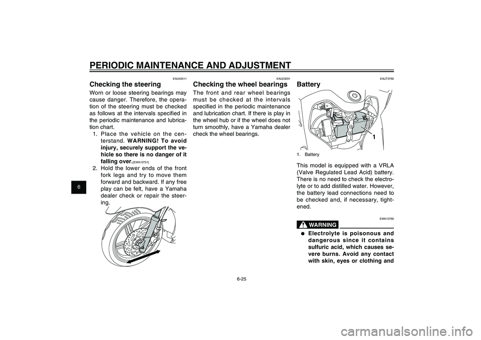
Battery
1
1. BatteryThis model is equipped with a VRLA
(Valve Regulated Lead Acid) battery.
There is no need to check the electro-
lyte or to add distilled water. However,
the battery lead connections need to
be checked and, if necessary, tight-
ened.
EWA10760
WARNING
●
Electrolyte is poisonous and
dangerous since it contains
sulfuric acid, which causes se-
vere burns. Avoid any contact
with skin, eyes or clothing and
EAU23291
Checking the wheel bearingsThe front and rear wheel bearings
must be checked at the intervals
specifi ed in the periodic maintenance
and lubrication chart. If there is play in
the wheel hub or if the wheel does not
turn smoothly, have a Yamaha dealer
check the wheel bearings.
EAU45511
Checking the steeringWorn or loose steering bearings may
cause danger. Therefore, the opera-
tion of the steering must be checked
as follows at the intervals specifi ed in
the periodic maintenance and lubrica-
tion chart.
1. Place the vehicle on the cen-
terstand. WARNING! To avoid
injury, securely support the ve-
hicle so there is no danger of it
falling over.
[EWA10751]
2. Hold the lower ends of the front
fork legs and try to move them
forward and backward. If any free
play can be felt, have a Yamaha
dealer check or repair the steer-
ing.
52S-F8199-E0_CS.indd 6-2552S-F8199-E0_CS.indd 6-25
2011/11/16 13:07:022011/11/16 13:07:02
Process BlackProcess Black
Page 63 of 84
1
2
3
4
5
6
7
8
9
6-26
EAU1722A
PERIODIC MAINTENANCE AND ADJUSTMENT
NOTICE:
When removing the
battery, be sure the key is
turned to “OFF”, then discon-
nect the negative lead before
disconnecting the positive
lead.
[ECA16302]
2. If the battery will be stored for
more than two months, check it
at least once a month and fully
charge it if necessary.
3. Fully charge the battery before
installing it.
NOTICE:
When in-
stalling the battery, be sure the
key is turned to “OFF”, then
connect the positive lead be-
fore connecting the negative
lead.
[ECA16840]
4. After installing the battery, make
sure that the battery leads are
properly connected to the battery
terminals.
5. Turn the key from “ON” to “OFF”
three times in three-second in-
tervals to initialize the idle speed
control system.
manently damage the battery.
The battery is located behind panel A.
Remove the panel to access the bat-
tery. (See page 6-7.)
To charge the battery
Have a Yamaha dealer charge the
battery as soon as possible if it seems
to have discharged. Keep in mind that
the battery tends to discharge more
quickly if the vehicle is equipped with
optional electrical accessories.
ECA16521
NOTICETo charge a VRLA (Valve Regu-
lated Lead Acid) battery, a special
(constant-voltage) battery charger
is required. Using a conventional
battery charger will damage the
battery.
To store the battery
1. If the vehicle will not be used for
more than one month, remove
the battery, fully charge it, and
then place it in a cool, dry place.
always shield your eyes when
working near batteries. In case
of contact, administer the fol-
lowing FIRST AID.
• EXTERNAL: Flush with plen-
ty of water.
• INTERNAL: Drink large quan-
tities of water or milk and im-
mediately call a physician.
• EYES: Flush with water for
15 minutes and seek prompt
medical attention.
●
Batteries produce explosive
hydrogen gas. Therefore, keep
sparks, � ames, cigarettes, etc.,
away from the battery and pro-
vide suf� cient ventilation when
charging it in an enclosed
space.
●
KEEP THIS AND ALL BATTER-
IES OUT OF THE REACH OF
CHILDREN.
ECA10620
NOTICENever attempt to remove the bat-
tery cell seals, as this would per-
52S-F8199-E0_CS.indd 6-2652S-F8199-E0_CS.indd 6-26
2011/11/16 13:07:022011/11/16 13:07:02
Process BlackProcess Black
Page 64 of 84
1
2
3
4
5
6
7
8
9
6-27
EAU1722A
PERIODIC MAINTENANCE AND ADJUSTMENT
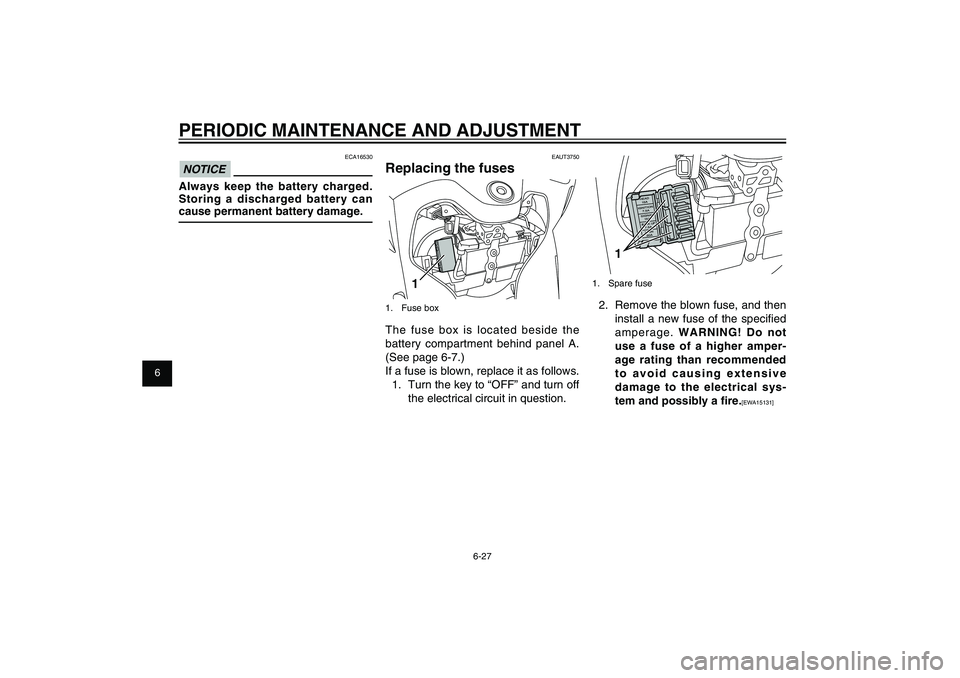
1
1. Spare fuse2. Remove the blown fuse, and then
install a new fuse of the specifi ed
amperage. WARNING! Do not
use a fuse of a higher amper-
age rating than recommended
to avoid causing extensive
damage to the electrical sys-
tem and possibly a � re.
[EWA15131] EAUT3750
Replacing the fuses
1
1. Fuse boxThe fuse box is located beside the
battery compartment behind panel A.
(See page 6-7.)
If a fuse is blown, replace it as follows.
1. Turn the key to “OFF” and turn off
the electrical circuit in question.
ECA16530
NOTICEAlways keep the battery charged.
Storing a discharged battery can
cause permanent battery damage.
52S-F8199-E0_CS.indd 6-2752S-F8199-E0_CS.indd 6-27
2011/11/16 13:07:022011/11/16 13:07:02
Process BlackProcess Black
Page 70 of 84
1
2
3
4
5
6
7
8
9
6-33
EAU1722A
PERIODIC MAINTENANCE AND ADJUSTMENT
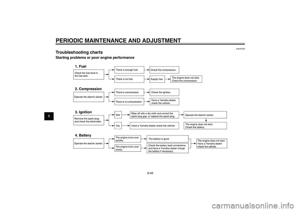
EAU42704
Troubleshooting chartsStarting problems or poor engine performance
Check the fuel level in
the fuel tank.1. Fuel
There is enough fuel.
There is no fuel.
Check the compression.
Supply fuel.
The engine does not start.
Check the compression.
Operate the electric starter.2. Compression
There is compression.
There is no compression.
Check the ignition.
Have a Yamaha dealer
check the vehicle.
Remove the spark plug
and check the electrodes.3. Ignition
Wipe off with a dry cloth and correct the
spark plug gap, or replace the spark plug.
Have a Yamaha dealer check the vehicle.
The engine does not start.
Have a Yamaha dealer
check the vehicle.
The engine does not start.
Check the battery.
Operate the electric starter.4. Battery
The engine turns over
quickly.
The engine turns over
slowly.
The battery is good.
DryWet
Operate the electric starter.
Check the battery lead connections,
and have a Yamaha dealer charge
the battery if necessary.
52S-F8199-E0_CS.indd 6-3352S-F8199-E0_CS.indd 6-33
2011/11/16 13:07:022011/11/16 13:07:02
Process BlackProcess Black
Page 75 of 84
1
2
3
4
5
6
7
8
9
7-4
EAU25991
SCOOTER CARE AND STORAGE
the fuel tank from rusting and the
fuel from deteriorating.
3. Perform the following steps to
protect the cylinder, piston rings,
etc. from corrosion.
a. Remove the spark plug cap
and spark plug.
b. Pour a teaspoonful of engine
oil into the spark plug bore.
c. Install the spark plug cap onto
the spark plug, and then place
the spark plug on the cylinder
head so that the electrodes are
grounded. (This will limit spark-
ing during the next step.)
d. Turn the engine over several
times with the starter. (This will
coat the cylinder wall with oil.)
e. Remove the spark plug cap
from the spark plug, and then
install the spark plug and the
spark plug cap. WARNING!
To prevent damage or injury
from sparking, make sure to
ground the spark plug elec-
trodes while turning the en-
gine over.
[EWA10951]
4. Lubricate all control cables and
the pivoting points of all levers
and pedals as well as of the
sidestand/centerstand.
5. Check and, if necessary, correct
the tire air pressure, and then
lift the scooter so that both of its
wheels are off the ground. Alter-
natively, turn the wheels a little
every month in order to prevent
the tires from becoming degraded
in one spot.
6. Cover the muffler outlet with a
plastic bag to prevent moisture
from entering it.
7. Remove the battery and fully
charge it. Store it in a cool,
dry place and charge it once a
month. Do not store the battery
in an excessively cold or warm
place [less than 0 °C (30 °F) or
more than 30 °C (90 °F)]. For
more information on storing the
battery, see page 6-26.
TIPMake any necessary repairs before
storing the scooter.
52S-F8199-E0_CS.indd 7-452S-F8199-E0_CS.indd 7-4
2011/11/16 13:07:022011/11/16 13:07:02
Process BlackProcess Black
Page 77 of 84

1
2
3
4
5
6
7
8
9
8-2
SPECIFICATIONS
Caster angle
23.83 degree
Trail
84 mm (3.3 in)Front tireType
Tubeless
Size
100 / 80 - 16M/C 50P
Manufacturer/model
DURO / DM1157FRear tireType
Tubeless
Size
120 / 80 - 16M/C 60P
Manufacturer/model
DURO / DM1157LoadingMaximum load
179 kg (395 lb)Tire air pressure (measured on cold
tires)Loading condition
90 kg (198 lb)
Front
175 kPa (1.75 kgf/cm
2, 25 psi, 1.75 bar)
Rear
200 kPa (2.00 kgf/cm2, 29 psi, 2.00 bar)
Loading condition
90 kg - maximum load
Front
175 kPa (1.75 kgf/cm2, 25 psi, 1.75 bar)Rear
225 kPa (2.25 kgf/cm
2, 33 psi, 2.25 bar)
Front wheelWheel type
Cast wheel
Rim size
J 16M/C x MT2.50Rear wheelWheel type
Cast wheel
Rim size
J 16M/C x MT2.75Front brakeType
Single disc brake
Operation
Right hand operation
Specifi ed brake fl uid
DOT 4Rear brakeType
Drum brake
Operation
Left hand operationFront suspensionType
Telescopic fork
Spring/shock absorber type
Coil spring/oil damper
Wheel travel
100.0 mm (3.94 in)Rear suspensionType
Unit swingSpring/shock absorber type
Coil spring/gas-oil damper
Wheel travel
92.0 mm (3.62 in)
Electrical systemIgnition system
TCI
Charging system
AC magnetoBatteryModel
GT7B-4
Voltage, capacity
12 V, 6.5 AhHeadlightBulb type
Halogen bulbBulb voltage, wattage x quantityHeadlight
12 V, 55 W x 2
Tail/brake light
12V, 0.25 / 1.4W x 1 (LED ASSY)
Front turn signal light
12 V, 10.0 W x 2
Rear turn signal light
12 V, 10.0 W x 2
Auxiliary light
12 V, 5.0 W x 2
License plate light
12 V, 5.0 W x 1
Meter lighting
12V,LED x 6
High beam indicator light
12V,LED x 1
52S-F8199-E0_CS.indd 8-252S-F8199-E0_CS.indd 8-2
2011/11/16 13:07:022011/11/16 13:07:02
Process BlackProcess Black
Page 80 of 84

INDEXAAcceleration and deceleration ................... 5-2
Air fi lter and V-belt case air fi lter
elements ............................................... 6-15
Auxiliary light bulb, replacing .................. 6-30BBattery ..................................................... 6-25
Brake fl uid, changing .............................. 6-22
Brake fl uid level, checking ...................... 6-21
Brake lever, front ....................................... 3-7
Brake lever, rear ....................................... 3-8
Brake levers, lubricating .......................... 6-23
Brake pads and shoes, checking ............ 6-20
Braking ...................................................... 5-2CCables, checking and lubricating ............ 6-22
Care .......................................................... 7-1
Carrier ..................................................... 3-14
Catalytic converter .................................. 3-10
Centerstand, checking and lubricating .... 6-23
Coolant .................................................... 6-13
Coolant temperature warning light ............ 3-2
Cowling and panels, removing and
installing .................................................. 6-7DDimmer switch .......................................... 3-7EEngine break-in ......................................... 5-3
Engine idling speed, checking ................ 6-16
Engine oil ................................................ 6-10
Engine trouble warning light ...................... 3-3FFinal transmission oil .............................. 6-12
Front brake lever free play, checking ...... 6-19Front fork, checking ................................ 6-24
Fuel ........................................................... 3-9
Fuel consumption, tips for reducing .......... 5-3
Fuel tank cap ............................................ 3-8
Fuses, replacing ...................................... 6-27
HHandlebar switches ................................... 3-7
Headlight bulb, replacing ........................ 6-28
High beam indicator light .......................... 3-2
Horn switch ............................................... 3-7IIdentifi cation numbers ............................... 9-1
Indicator lights and warning lights ............. 3-2LLicense plate light ................................... 6-31
Luggage holder ....................................... 3-14MMaintenance, emission control system ..... 6-3
Maintenance and lubrication, periodic ...... 6-4
Main switch/steering lock .......................... 3-1
Matte color, caution ................................... 7-1
Model label ................................................ 9-1
Multi-function display ................................ 3-3PParking ...................................................... 5-4
Part locations ............................................ 2-1
Passenger footrest .................................. 3-12RRear brake lever free play, adjusting ...... 6-19SSafe-riding points ...................................... 1-5
Safety information ..................................... 1-1
Seat ......................................................... 3-11
Shock absorber assembly ....................... 3-13Spark plug, checking ................................. 6-9
Specifi cations ............................................ 8-1
Starting off ................................................. 5-2
Starting the engine .................................... 5-1
Start switch ............................................... 3-7
Steering, checking .................................. 6-25
Storage ..................................................... 7-3
Storage compartment (front) ................... 3-12
Storage compartment (rear) .................... 3-13
TTail/brake light ......................................... 6-29
Throttle grip and cable, checking and
lubricating ............................................. 6-23
Throttle grip free play, checking .............. 6-16
Tires ........................................................ 6-17
Tool kit ...................................................... 6-2
Troubleshooting ...................................... 6-32
Troubleshooting charts ........................... 6-33
Turn signal indicator lights ........................ 3-2
Turn signal light bulb (front), replacing .... 6-29
Turn signal light bulb (rear), replacing .... 6-31
Turn signal switch ..................................... 3-7VValve clearance ...................................... 6-17
Vehicle identifi cation number .................... 9-1WWheels .................................................... 6-19
Wheel bearings, checking ....................... 6-25
52S-F8199-E0_CS.indd 9-252S-F8199-E0_CS.indd 9-2
2011/11/16 13:07:022011/11/16 13:07:02
Process BlackProcess Black