turn signal YAMAHA XJ6-S 2012 User Guide
[x] Cancel search | Manufacturer: YAMAHA, Model Year: 2012, Model line: XJ6-S, Model: YAMAHA XJ6-S 2012Pages: 102, PDF Size: 2.68 MB
Page 81 of 102
![YAMAHA XJ6-S 2012 User Guide PERIODIC MAINTENANCE AND ADJUSTMENT
6-35
6
is turned to “OFF”, then con-
nect the positive lead before
connecting the negative lead.
[ECA16840]
4. After installation, make sure that
the battery le](/img/51/52609/w960_52609-80.png "YAMAHA XJ6-S 2012 User Guide PERIODIC MAINTENANCE AND ADJUSTMENT
6-35
6
is turned to “OFF”, then con-
nect the positive lead before
connecting the negative lead.
[ECA16840]
4. After installation, make sure that
the battery le")
PERIODIC MAINTENANCE AND ADJUSTMENT
6-35
6
is turned to “OFF”, then con-
nect the positive lead before
connecting the negative lead.
[ECA16840]
4. After installation, make sure that
the battery leads are properly con-
nected to the battery terminals.NOTICE
ECA16530
Always keep the battery charged.
Storing a discharged battery can
cause permanent battery damage.
EAU52200
Replacing the fuses The main fuse and the fuse boxes are
located under the seat. (See page
3-18.)TIPTo access the main fuse, remove the
starter relay cover as shown.
The siren fuse and the patrol light fuse
are located behind the front cowling.
1. Starter relay cover
2. Main fuse
3. Spare main fuse
4. Fuse box
2
4
3
1
1. Taillight fuse
2. ABS control unit fuse
3. Police system fuse
4. ABS solenoid fuse
5. ABS motor fuse
6. Spare fuse
7. Headlight fuse
8. Ignition fuse
9. Signaling system fuse
10.Backup fuse (for clock and immobilizer sys-
tem)
11.Fuel injection system fuse
12.Radiator fan fuse
1
6 67
8
9
10
11
12
24
35
U1PWEAE0.book Page 35 Tuesday, February 7, 2012 4:21 PM
Page 82 of 102
PERIODIC MAINTENANCE AND ADJUSTMENT
6-36
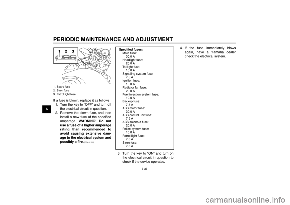
6If a fuse is blown, replace it as follows.
1. Turn the key to “OFF” and turn off the electrical circuit in question.
2. Remove the blown fuse, and then install a new fuse of the specified
amperage. WARNING! Do not
use a fuse of a higher amperage
rating than recommended to
avoid causing extensive dam-
age to the electrical system and
possibly a fire.
[EWA15131]
3. Turn the key to “ON” and turn on the electrical circuit in question to
check if the device operates. 4. If the fuse immediately blows
again, have a Yamaha dealer
check the electrical system.
1. Spare fuse
2. Siren fuse
3. Patrol light fuse
12 3
Specified fuses:Main fuse:
30.0 A
Headlight fuse:
20.0 A
Taillight fuse: 10.0 A
Signaling system fuse: 7.5 A
Ignition fuse:
10.0 A
Radiator fan fuse: 20.0 A
Fuel injection system fuse: 10.0 A
Backup fuse:
7.5 A
ABS motor fuse: 30.0 A
ABS control unit fuse: 7.5 A
ABS solenoid fuse:
20.0 A
Police system fuse: 10.0 A
Patrol light fuse: 7.5 A
Siren fuse:
7.5 A
U1PWEAE0.book Page 36 Tuesday, February 7, 2012 4:21 PM
Page 84 of 102
PERIODIC MAINTENANCE AND ADJUSTMENT
6-38
6
EAU47021
Replacing the tail/brake light
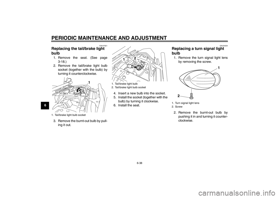
bulb 1. Remove the seat. (See page3-18.)
2. Remove the tail/brake light bulb socket (together with the bulb) by
turning it counterclockwise.
3. Remove the burnt-out bulb by pull- ing it out. 4. Insert a new bulb into the socket.
5. Install the socket (together with the
bulb) by turning it clockwise.
6. Install the seat.
EAU24204
Replacing a turn signal light
bulb 1. Remove the turn signal light lens by removing the screw.
2. Remove the burnt-out bulb by pushing it in and turning it counter-
clockwise.
1. Tail/brake light bulb socket
1
1. Tail/brake light bulb
2. Tail/brake light bulb socket
2
1
1. Turn signal light lens
2. Screw
1
2
U1PWEAE0.book Page 38 Tuesday, February 7, 2012 4:21 PM
Page 85 of 102
PERIODIC MAINTENANCE AND ADJUSTMENT
6-39
6
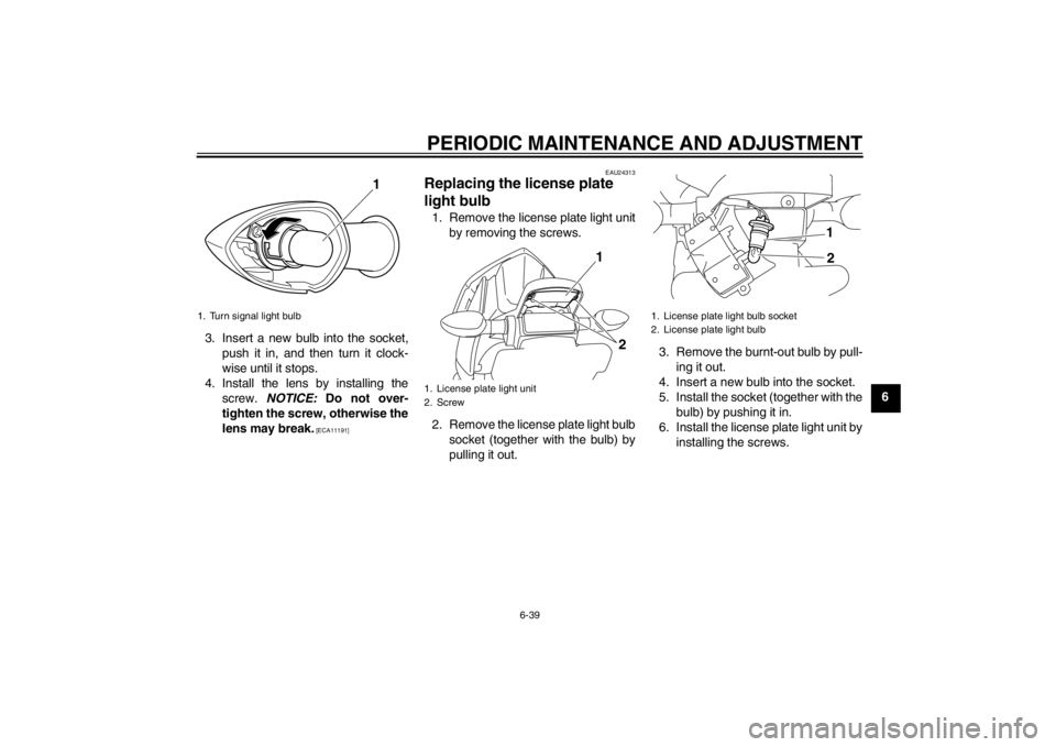
3. Insert a new bulb into the socket,
push it in, and then turn it clock-
wise until it stops.
4. Install the lens by installing the screw. NOTICE: Do not over-
tighten the screw, otherwise the
lens may break.
[ECA11191] EAU24313
Replacing the license plate
light bulb 1. Remove the license plate light unit
by removing the screws.
2. Remove the license plate light bulb socket (together with the bulb) by
pulling it out. 3. Remove the burnt-out bulb by pull-
ing it out.
4. Insert a new bulb into the socket.
5. Install the socket (together with the bulb) by pushing it in.
6. Install the license plate light unit by installing the screws.
1. Turn signal light bulb
1
1. License plate light unit
2. Screw
2
1
1. License plate light bulb socket
2. License plate light bulb
1
2
U1PWEAE0.book Page 39 Tuesday, February 7, 2012 4:21 PM
Page 96 of 102

SPECIFICATIONS
8-3
8
Voltage, capacity:12 V, 10.0 AhHeadlight:Bulb type:
Halogen bulbBulb voltage, wattage × quantity:Headlight:
12 V, 60.0 W/55.0 W × 1
Tail/brake light:
12 V, 5.0 W/21.0 W × 1
Front turn signal light: 12 V, 10.0 W × 2
Rear turn signal light: 12 V, 10.0 W × 2
Auxiliary light:
12 V, 5.0 W × 1
License plate light: 12 V, 5.0 W × 1
Meter lighting: LED
Neutral indicator light:
LED
High beam indicator light: LED
Oil level warning light: LED
Turn signal indicator light:
LED
Coolant temperature warning light: LED
Engine trouble warning light: LED
ABS warning light:
LED Immobilizer system indicator light:
LED
Fuses:Main fuse:
30.0 A
Headlight fuse: 20.0 A
Taillight fuse: 10.0 A
Signaling system fuse:
7.5 A
Ignition fuse: 10.0 A
Radiator fan fuse: 20.0 A
Fuel injection system fuse:
10.0 A
ABS control unit fuse: 7.5 A
ABS motor fuse: 30.0 A
ABS solenoid fuse:
20.0 A
Patrol light fuse: 7.5 A
Siren fuse: 7.5 A
Police system fuse:
10.0 A
Backup fuse: 7.5 A
U1PWEAE0.book Page 3 Tuesda y, February 7, 2012 4:21 PM
Page 99 of 102

INDEX
Throttle grip and cable, checking and lubricating ..................... 6-30
Throttle grip free play, checking ........... 6-20
Tires...................................................... 6-20
Tool kit .................................................... 6-2
Troubleshooting .................................... 6-40
Troubleshooting charts ......................... 6-41
Turn signal indicator light........................ 3-4
Turn signal light bulb, replacing ............ 6-38
Turn signal switch ................................. 3-12VValve clearance .................................... 6-20
Vehicle identification number.................. 9-1WWheel bearings, checking .................... 6-33
Wheels.................................................. 6-23
U1PWEAE0.book Page 2 Tuesda y, February 7, 2012 4:21 PM