fuel YAMAHA XJ6-S 2014 User Guide
[x] Cancel search | Manufacturer: YAMAHA, Model Year: 2014, Model line: XJ6-S, Model: YAMAHA XJ6-S 2014Pages: 104, PDF Size: 2.84 MB
Page 45 of 104
OPERATION AND IMPORTANT RIDING POINTS
5-4
5
1600 km (1000 mi) an
d b eyon d
The vehicle can now be operated nor-
mally.
NOTICE
ECA10311
Keep the en gine speed out of
the tachometer re d zone.
If any en gine trou ble shoul d oc-
cur durin g the en gine break-in
period , imme diately have a
Yamaha dealer check the vehi-
cle.
EAU17214
Parkin gWhen parking, stop the engine, and
then remove the key from the main
switch.
WARNING
EWA10312
Since the en gine an d exhaust
system can b ecome very hot,
park in a place where ped estri-
ans or chil dren are not likely to
touch them an d b e burne d.
Do not park on a slope or on soft
groun d, otherwise the vehicle
may overturn, increasin g the
risk of a fuel leak an d fire.
Do not park near grass or other
flamma ble materials which
mi ght catch fire.
U36CE4E0.book Page 4 Tuesday, July 2, 2013 3:47 PM
Page 48 of 104
PERIODIC MAINTENANCE AND ADJUSTMENT
6-3
6
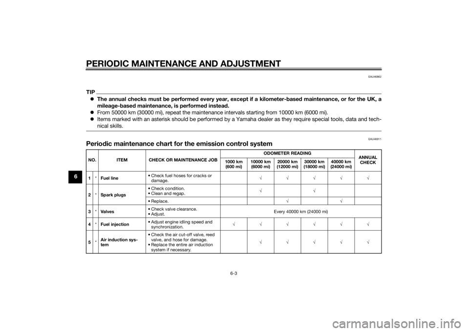
EAU46862
TIPThe annual checks must b e performed every year, except if a kilometer- based maintenance, or for the UK, a
milea ge- base d maintenance, is performe d instead .
From 50000 km (30000 mi), repeat the maintenance intervals starting from 10000 km (6000 mi).
Items marked with an asterisk should be performed by a Yamaha dealer as they require special tools, data and tech-
nical skills.
EAU46911
Perio dic maintenance chart for the emission control systemNO. ITEM CHECK OR MAINTENANCE JOB ODOMETER READING
ANNUAL
CHECK
1000 km
(600 mi) 10000 km
(6000 mi) 20000 km
(12000 mi) 30000 km
(18000 mi) 40000 km
(24000 mi)
1 *Fuel line • Check fuel hoses for cracks or
damage. √√√√√
2 *Spark plu gs • Check condition.
• Clean and regap.
√√
• Replace. √√
3 *Va l ve s • Check valve clearance.
•Adjust.
Every 40000 km (24000 mi)
4 *Fuel injection • Adjust engine idling speed and
synchronization. √√√√√√
5 *Air in
duction sys-
tem • Check the air cut-off valve, reed
valve, and hose for damage.
• Replace the entire air induction system if necessary. √√√√√
U36CE4E0.book Page 3 Tuesday, July 2, 2013 3:47 PM
Page 63 of 104
PERIODIC MAINTENANCE AND ADJUSTMENT
6-18
6
EAU32888
Replacing the air filter ele-
mentThe air filter element should be re-
placed at the intervals specified in the
periodic maintenance and lubrication
chart. Replace the air filter element
more frequently if you are riding in un-
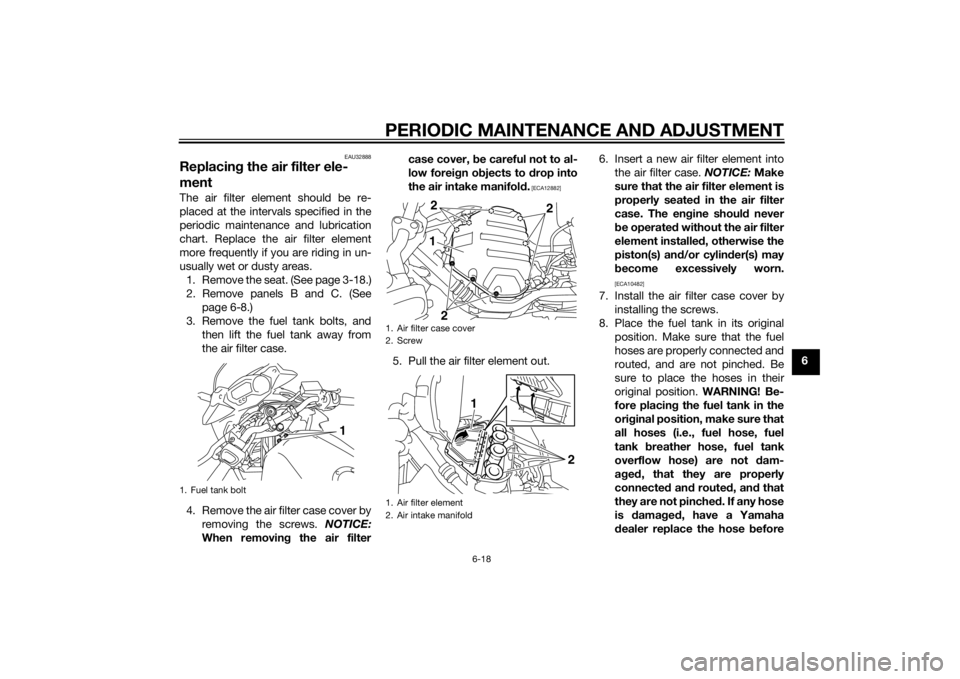
usually wet or dusty areas.
1. Remove the seat. (See page 3-18.)
2. Remove panels B and C. (See page 6-8.)
3. Remove the fuel tank bolts, and then lift the fuel tank away from
the air filter case.
4. Remove the air filter case cover by removing the screws. NOTICE:
When removin g the air filter case cover,
be careful not to al-
low forei gn o bjects to drop into
the air intake manifold .
[ECA12882]
5. Pull the air filter element out. 6. Insert a new air filter element into
the air filter case. NOTICE: Make
sure that the air filter element is
properly seated in the air filter
case. The en gine shoul d never
b e operated without the air filter
element installed , otherwise the
piston(s) an d/or cylin der(s) may
b ecome excessively worn.
[ECA10482]
7. Install the air filter case cover by
installing the screws.
8. Place the fuel tank in its original position. Make sure that the fuel
hoses are properly connected and
routed, and are not pinched. Be
sure to place the hoses in their
original position. WARNING! Be-
fore placin g the fuel tank in the
ori ginal position, make sure that
all hoses (i.e., fuel hose, fuel
tank breather hose, fuel tank
overflow hose) are not dam-
a g ed , that they are properly
connected and route d, an d that
they are not pinche d. If any hose
is damag ed , have a Yamaha
d ealer replace the hose before
1. Fuel tank bolt
1
1. Air filter case cover
2. Screw
1. Air filter element
2. Air intake manifold
12
2
2
2
1
U36CE4E0.book Page 18 Tuesday, July 2, 2013 3:47 PM
Page 64 of 104
![YAMAHA XJ6-S 2014 User Guide PERIODIC MAINTENANCE AND ADJUSTMENT
6-19
6starting
the en gine, otherwise
fuel may leak, creatin g a fire
hazar d.
[EWA12464]
9. Install the fuel tank bolts.
10. Install the panels.
11. Install the YAMAHA XJ6-S 2014 User Guide PERIODIC MAINTENANCE AND ADJUSTMENT
6-19
6starting
the en gine, otherwise
fuel may leak, creatin g a fire
hazar d.
[EWA12464]
9. Install the fuel tank bolts.
10. Install the panels.
11. Install the](/img/51/52607/w960_52607-63.png)
PERIODIC MAINTENANCE AND ADJUSTMENT
6-19
6starting
the en gine, otherwise
fuel may leak, creatin g a fire
hazar d.
[EWA12464]
9. Install the fuel tank bolts.
10. Install the panels.
11. Install the seat.
EAU34302
A djustin g the eng ine idlin g
spee dThe engine idling speed must be
checked and, if necessary, adjusted as
follows at the intervals specified in the
periodic maintenance and lubrication
chart.
The engine should be warm before
making this adjustment.
Check the engine idling speed and, if
necessary, adjust it to specification by
turning the idle adjusting screw. To in-
crease the engine idling speed, turn
the screw in direction (a). To decrease
the engine idling speed, turn the screw
in direction (b).
TIPIf the specified idling speed cannot be
obtained as described above, have a
Yamaha dealer make the adjustment.
1. Hose
1. Original position (paint mark)
1
1
1. Idle adjusting screw
1
(a)
(b)
En gine i dlin g spee d:
1250–1350 r/min
U36CE4E0.book Page 19 Tuesday, July 2, 2013 3:47 PM
Page 65 of 104
PERIODIC MAINTENANCE AND ADJUSTMENT
6-20
6
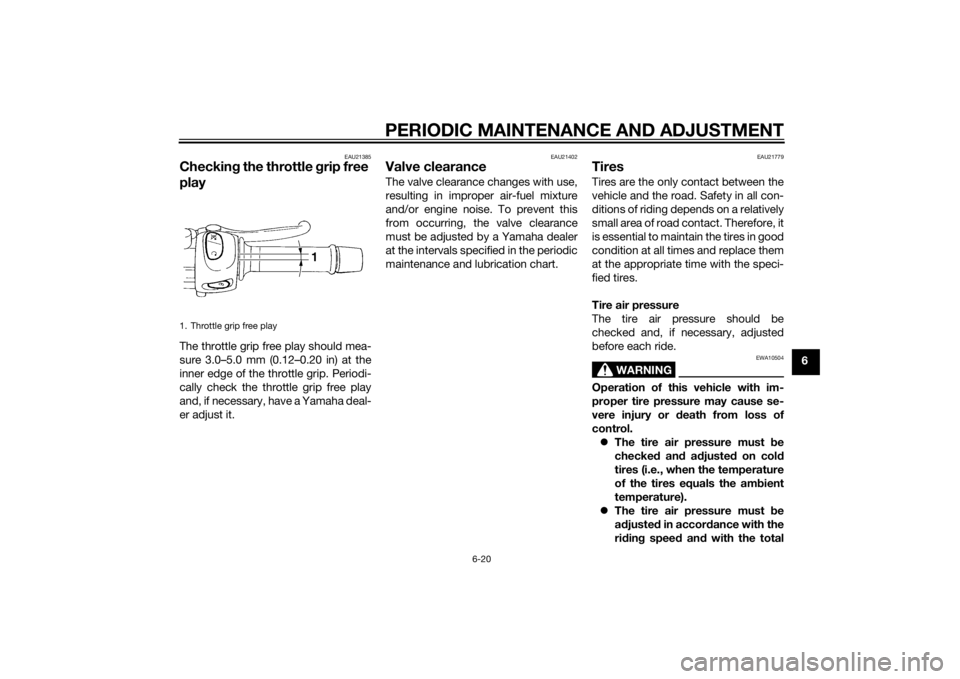
EAU21385
Checking the throttle grip free
playThe throttle grip free play should mea-
sure 3.0–5.0 mm (0.12–0.20 in) at the
inner edge of the throttle grip. Periodi-
cally check the throttle grip free play
and, if necessary, have a Yamaha deal-
er adjust it.
EAU21402
Valve clearanceThe valve clearance changes with use,
resulting in improper air-fuel mixture
and/or engine noise. To prevent this
from occurring, the valve clearance
must be adjusted by a Yamaha dealer
at the intervals specified in the periodic
maintenance and lubrication chart.
EAU21779
TiresTires are the only contact between the
vehicle and the road. Safety in all con-
ditions of riding depends on a relatively
small area of road contact. Therefore, it
is essential to maintain the tires in good
condition at all times and replace them
at the appropriate time with the speci-
fied tires.
Tire air pressure
The tire air pressure should be
checked and, if necessary, adjusted
before each ride.
WARNING
EWA10504
Operation of this vehicle with im-
proper tire pressure may cause se-
vere injury or d eath from loss of
control. The tire air pressure must be
checked and a djuste d on col d
tires (i.e., when the temperature
of the tires equals the am bient
temperature).
The tire air pressure must be
a d juste d in accor dance with the
ri din g spee d an d with the total
1. Throttle grip free play
U36CE4E0.book Page 20 Tuesday, July 2, 2013 3:47 PM
Page 81 of 104
PERIODIC MAINTENANCE AND ADJUSTMENT
6-36
6
EAU47173
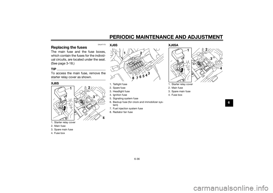
Replacing the fusesThe main fuse and the fuse boxes,
which contain the fuses for the individ-
ual circuits, are located under the seat.
(See page 3-18.)TIPTo access the main fuse, remove the
starter relay cover as shown.XJ6S XJ6S XJ6SA1. Starter relay cover
2. Main fuse
3. Spare main fuse
4. Fuse box
2
4
3
1
1. Taillight fuse
2. Spare fuse
3. Headlight fuse
4. Ignition fuse
5. Signaling system fuse
6. Backup fuse (for clock and immobilizer sys-
tem)
7. Fuel injection system fuse
8. Radiator fan fuse
1 2
3
4
5
6
7
8
1. Starter relay cover
2. Main fuse
3. Spare main fuse
4. Fuse box
2
4
3
1
U36CE4E0.book Page 36 Tuesday, July 2, 2013 3:47 PM
Page 82 of 104
PERIODIC MAINTENANCE AND ADJUSTMENT
6-37
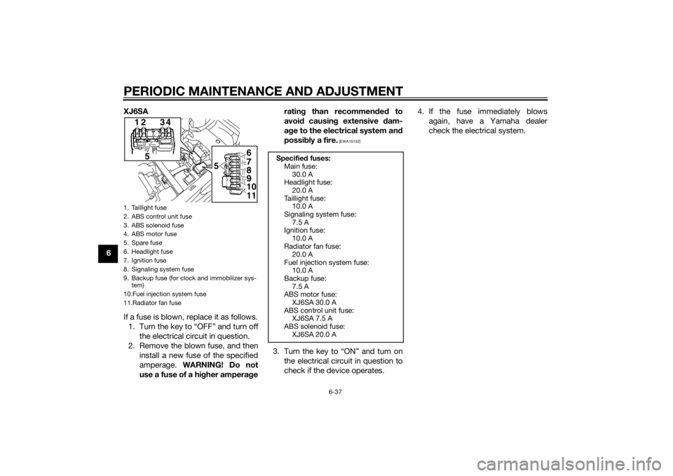
6XJ6SA
If a fuse is blown, replace it as follows.
1. Turn the key to “OFF” and turn off the electrical circuit in question.
2. Remove the blown fuse, and then install a new fuse of the specified
amperage. WARNING! Do not
use a fuse of a hi gher ampera ge ratin
g than recommen ded to
avoi d causin g extensive d am-
a g e to the electrical system an d
possi bly a fire.
[EWA15132]
3. Turn the key to “ON” and turn on
the electrical circuit in question to
check if the device operates. 4. If the fuse immediately blows
again, have a Yamaha dealer
check the electrical system.
1. Taillight fuse
2. ABS control unit fuse
3. ABS solenoid fuse
4. ABS motor fuse
5. Spare fuse
6. Headlight fuse
7. Ignition fuse
8. Signaling system fuse
9. Backup fuse (for clock and immobilizer sys-tem)
10.Fuel injection system fuse
11.Radiator fan fuse
1
5 56
7
8
9
10
11
234
Specifie
d fuses:
Main fuse: 30.0 A
Headlight fuse:
20.0 A
Taillight fuse: 10.0 A
Signaling system fuse: 7.5 A
Ignition fuse:
10.0 A
Radiator fan fuse: 20.0 A
Fuel injection system fuse: 10.0 A
Backup fuse:
7.5 A
ABS motor fuse: XJ6SA 30.0 A
ABS control unit fuse: XJ6SA 7.5 A
ABS solenoid fuse:
XJ6SA 20.0 A
U36CE4E0.book Page 37 Tuesday, July 2, 2013 3:47 PM
Page 89 of 104
PERIODIC MAINTENANCE AND ADJUSTMENT
6-44
6
4. Adjust the drive chain slack. (See
page 6-28.)
5. Take the motorcycle off the cen- terstand so that the rear wheel is
on the ground, and then put the
sidestand down.
6. Tighten the axle nut, and then tighten the locknuts to the speci-
fied torques.
EAU25872
Trou bleshootin gAlthough Yamaha motorcycles receive
a thorough inspection before shipment
from the factory, trouble may occur
during operation. Any problem in the
fuel, compression, or ignition systems,
for example, can cause poor starting
and loss of power.
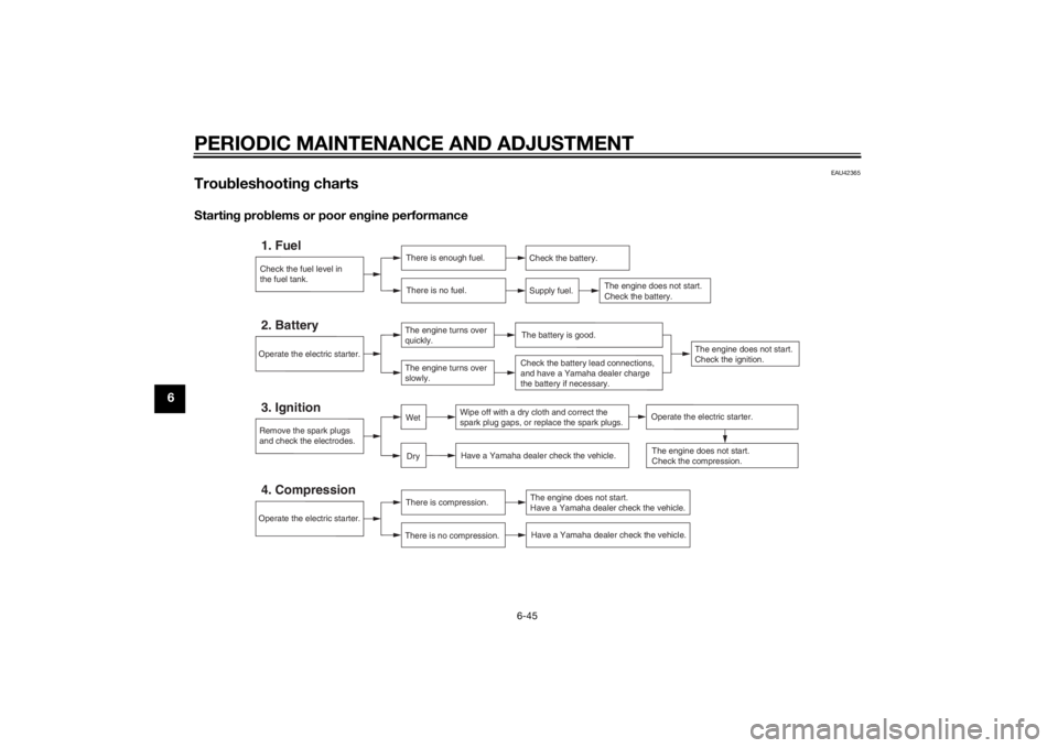
The following troubleshooting charts
represent quick and easy procedures
for checking these vital systems your-
self. However, should your motorcycle
require any repair, take it to a Yamaha
dealer, whose skilled technicians have
the necessary tools, experience, and
know-how to service the motorcycle
properly.
Use only genuine Yamaha replace-
ment parts. Imitation parts may look
like Yamaha parts, but they are often
inferior, have a shorter service life and
can lead to expensive repair bills.
WARNING
EWA15142
When checkin g the fuel system, d o
not smoke, an d make sure there are
no open flames or sparks in the ar-
ea, inclu din g pilot li ghts from water heaters or furnaces. Gasoline or
g
asoline vapors can i gnite or ex-
plo de, causin g severe injury or prop-
erty damag e.
Tightenin g torques:
Axle nut: 90 Nm (9.0 m·kgf, 65 ft·lbf)
Locknut:
16 Nm (1.6 m·kgf, 12 ft·lbf)
U36CE4E0.book Page 44 Tuesday, July 2, 2013 3:47 PM
Page 90 of 104
PERIODIC MAINTENANCE AND ADJUSTMENT
6-45
6
EAU42365
Troubleshootin g chartsStartin g pro blems or poor en gine performance
Check the fuel level in
the fuel tank.1. Fuel
There is enough fuel.
There is no fuel.
Check the battery.
Supply fuel.
The engine does not start.
Check the battery.
Remove the spark plugs
and check the electrodes.3. Ignition
Wipe off with a dry cloth and correct the
spark plug gaps, or replace the spark plugs.
Have a Yamaha dealer check the vehicle.
Operate the electric starter.4. Compression
There is compression.
There is no compression.
The engine does not start.
Have a Yamaha dealer check the vehicle.Have a Yamaha dealer check the vehicle.
The engine does not start.
Check the compression.
Operate the electric starter.2. Battery
The engine turns over
quickly.
The engine turns over
slowly.
The engine does not start.
Check the ignition.
The battery is good.Check the battery lead connections,
and have a Yamaha dealer charge
the battery if necessary.
DryWet
Operate the electric starter.
U36CE4E0.book Page 45 Tuesday, July 2, 2013 3:47 PM
Page 93 of 104
MOTORCYCLE CARE AND STORAGE7-2
7
off any
deter gent resi due usin g
plenty of water, as it is harmful
to plastic parts.
Do not use any harsh chemical
prod ucts on plastic parts. Be
sure to avoi d usin g cloths or
spon ges which have b een in
contact with stron g or a brasive
cleanin g prod ucts, solvent or
thinner, fuel ( gasoline), rust re-
movers or inhi bitors, brake flui d,
antifreeze or electrolyte.
Do not use hi gh-pressure wash-
ers or steam-jet cleaners since
they cause water seepag e and
d eterioration in the followin g ar-
eas: seals (of wheel an d swin g-
arm bearin gs, fork an d b rakes),
electric components (couplers,
connectors, instruments,
switches an d li ghts), breather
hoses an d vents.
For motorcycles equippe d with
a win dshiel d: Do not use stron g
cleaners or har d spon ges as
they will cause dullin g
or
sc
ratchin g. Some cleanin g
compoun ds for plastic may
leave scratches on the win d- shiel
d. Test the pro duct on a
small hi dden part of the win d-
shiel d to make sure that it does
not leave any marks. If the win d-
shiel d is scratche d, use a quality
plastic polishin g compoun d af-
ter washing .
After normal useRemove dirt with warm water, a mild
detergent, and a soft, clean sponge,
and then rinse thoroughly with clean
water. Use a toothbrush or bottlebrush
for hard-to-reach areas. Stubborn dirt
and insects will come off more easily if
the area is covered with a wet cloth for
a few minutes before cleaning.
After riding in the rain, near the sea oron salt-sprayed roadsSince sea salt or salt sprayed on roads
during winter are extremely corrosive
in combination with water, carry out
the following steps after each ride in
the rain, near the sea or on salt-
sprayed roads.
TIPSalt sprayed on roads in the winter
may remain well into spring.1. Clean the motorcycle with cold
water and a mild detergent, after
the engine has cooled down.
NOTICE: Do not use warm wa-
ter since it increases the corro-
sive action of the salt.
[ECA10792]
2. Apply a corrosion protection spray on all metal, including chrome-
and nickel-plated, surfaces to pre-
vent corrosion.
Cleaning the windshieldAvoid using any alkaline or strong acid
cleaner, gasoline, brake fluid, or any
other solvent. Clean the windshield
with a cloth or sponge dampened with
a mild detergent, and then wash it off
thoroughly with water. For additional
cleaning, use Yamaha Windshield
Cleaner or another high-quality wind-
shield cleaner. Some cleaning com-
pounds for plastics may leave
scratches on the windshield. Before
using such cleaners, test an area of the
U36CE4E0.book Page 2 Tuesday, July 2, 2013 3:47 PM