fork YAMAHA XJ900S 2000 Owners Manual
[x] Cancel search | Manufacturer: YAMAHA, Model Year: 2000, Model line: XJ900S, Model: YAMAHA XJ900S 2000Pages: 97, PDF Size: 2.08 MB
Page 12 of 97
DESCRIPTION
2-2
2
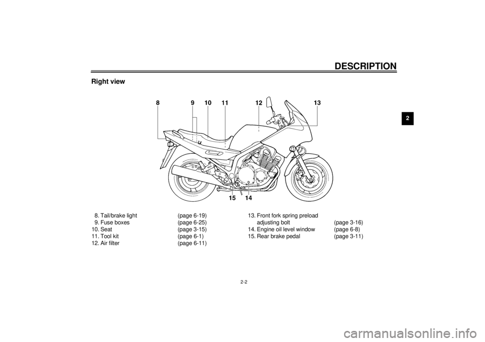
Right view8. Tail/brake light (page 6-19)
9. Fuse boxes (page 6-25)
10. Seat (page 3-15)
11. Tool kit (page 6-1)
12. Air filter (page 6-11)13. Front fork spring preload
adjusting bolt (page 3-16)
14. Engine oil level window (page 6-8)
15. Rear brake pedal (page 3-11)
Page 14 of 97
3
INSTRUMENT AND CONTROL FUNCTIONS
Main switch/steering lock ...................................... 3-1
Indicator lights ...................................................... 3-3
Oil level indicator circuit check .............................. 3-4
Fuel indicator circuit check ................................... 3-5
Speedometer ........................................................ 3-6
Tachometer ........................................................... 3-6
Diagnosis device................................................... 3-7
Antitheft alarm (optional) ...................................... 3-7
Fuel gauge ............................................................ 3-8
Digital clock........................................................... 3-8
Handlebar switches .............................................. 3-9
Clutch lever ......................................................... 3-10
Shift pedal ........................................................... 3-11Front brake lever ................................................ 3-11
Rear brake pedal................................................ 3-11
Fuel tank cap ..................................................... 3-12
Fuel .................................................................... 3-13
Fuel tank breather hose (for Germany only) ...... 3-14
Starter (choke) “ ” ........................................... 3-14
Seat.................................................................... 3-15
Helmet holder..................................................... 3-15
Storage compartment ........................................ 3-16
Front fork adjustment ......................................... 3-16
Rear shock absorber adjustment ....................... 3-17
Sidestand ........................................................... 3-18
Sidestand/clutch switch operation check............ 3-18
Page 30 of 97
INSTRUMENT AND CONTROL FUNCTIONS
3-16
3
EAU01688
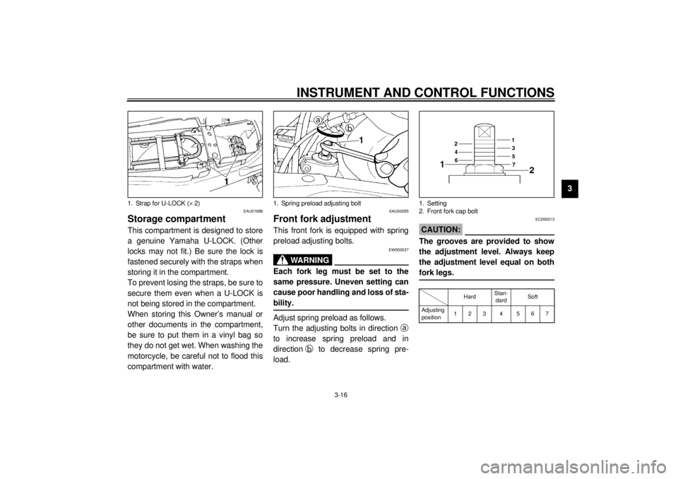
Storage compartmentThis compartment is designed to store
a genuine Yamaha U-LOCK. (Other
locks may not fit.) Be sure the lock is
fastened securely with the straps when
storing it in the compartment.
To prevent losing the straps, be sure to
secure them even when a U-LOCK is
not being stored in the compartment.
When storing this Owner’s manual or
other documents in the compartment,
be sure to put them in a vinyl bag so
they do not get wet. When washing the
motorcycle, be careful not to flood this
compartment with water.
EAU00285
Front fork adjustmentThis front fork is equipped with spring
preload adjusting bolts.
EW000037
WARNING
@ Each fork leg must be set to the
same pressure. Uneven setting can
cause poor handling and loss of sta-
bility. @Adjust spring preload as follows.
Turn the adjusting bolts in direction
a
to increase spring preload and in
direction
b to decrease spring pre-
load.
EC000013
CAUTION:@ The grooves are provided to show
the adjustment level. Always keep
the adjustment level equal on both
fork legs. @CI-18E
1. Strap for U-LOCK (´ 2)
1. Spring preload adjusting bolt
1. Setting
2. Front fork cap bolt
HardStan-
dardSoft
Adjusting
position123 4 567
Page 46 of 97
6
PERIODIC MAINTENANCE AND MINOR REPAIR
Tool kit................................................................... 6-1
Periodic maintenance and lubrication ................... 6-2
Cowling removal and installation .......................... 6-5
Cowling A.............................................................. 6-5
Cowling B.............................................................. 6-6
Spark plug inspection ........................................... 6-7
Engine oil .............................................................. 6-8
Final gear oil replacement .................................. 6-11
Air filter ............................................................... 6-11
Carburetor adjustment ........................................ 6-13
Idle speed adjustment ........................................ 6-13
Throttle cable free play inspection ...................... 6-14
Valve clearance adjustment ................................ 6-14
Tires .................................................................... 6-15
Wheels ................................................................ 6-18
Clutch lever free play adjustment........................ 6-18
Brake light switch adjustment ............................. 6-19
Checking the front and rear brake pads.............. 6-19
Inspecting the brake fluid level............................ 6-20Brake fluid replacement ..................................... 6-21
Cable inspection and lubrication ........................ 6-21
Throttle cable and grip lubrication ...................... 6-21
Brake and shift pedal lubrication ........................ 6-22
Brake and clutch lever lubrication ...................... 6-22
Center and sidestand lubrication ....................... 6-22
Front fork inspection ........................................... 6-23
Steering inspection ............................................ 6-23
Wheel bearings .................................................. 6-24
Battery................................................................ 6-24
Fuse replacement .............................................. 6-25
Headlight bulb replacement ............................... 6-26
Front wheel removal ........................................... 6-27
Front wheel installation ...................................... 6-29
Rear wheel removal ........................................... 6-30
Rear wheel installation ....................................... 6-31
Troubleshooting .................................................. 6-31
Troubleshooting chart ......................................... 6-32
Page 49 of 97

PERIODIC MAINTENANCE AND MINOR REPAIR
6-3
6
11
*Wheel bearings• Check bearing for looseness or damage.
• Replace if necessary. ÖÖ
12*Swingarm• Check swingarm pivoting point for play.
• Correct if necessary.
• Lubricate with molybdenum disulfide grease every 24,000 km or
24 months (whichever comes first).ÖÖ
13*Steering bearings• Check bearing play and steering for roughness.
• Correct accordingly.
• Lubricate with lithium soap base grease every 24,000 km
or 24 months (whichever comes first).ÖÖ
14*Chassis fasteners• Make sure that all nuts, bolts and screws are properly tightened.
• Tighten if necessary.ÖÖ
15 Sidestand/centerstand• Check operation.
• Lubricate and repair if necessary.ÖÖ
16*Sidestand switch• Check operation.
• Replace if necessary.ÖÖÖ
17*Front fork• Check operation and for oil leakage.
• Correct accordingly.ÖÖ
18*Rear shock absorber
assembly• Check operation and shock absorber for oil leakage.
• Replace shock absorber assembly if necessary. ÖÖ
19*Rear suspension relay
arm and connecting arm
pivoting points• Check operation.
• Lubricate with molybdenum disulfide grease every 24,000 km or
24 months (whichever comes first).ÖÖ
20*Carburetors• Check engine idling speed, synchronization and starter operation.
• Adjust if necessary.ÖÖÖ
21 Engine oil• Check oil level and vehicle for oil leakage.
• Correct if necessary.
• Change. (Warm engine before draining.)ÖÖÖ NO. ITEM CHECKS AND MAINTENANCE JOBSINITIAL
(1,000 km)EVERY
6,000 km
or
6 months
(whichever
comes first)12,000 km
or
12 months
(whichever
comes first)
Page 69 of 97
PERIODIC MAINTENANCE AND MINOR REPAIR
6-23
6
EAU02939
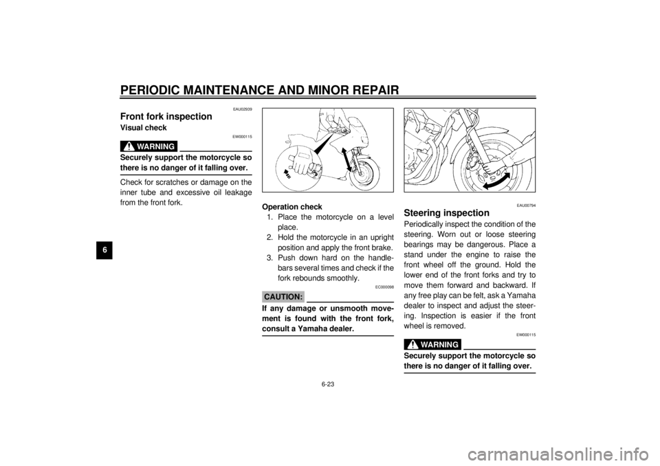
Front fork inspectionVisual check
EW000115
WARNING
@ Securely support the motorcycle so
there is no danger of it falling over. @Check for scratches or damage on the
inner tube and excessive oil leakage
from the front fork.
Operation check
1. Place the motorcycle on a level
place.
2. Hold the motorcycle in an upright
position and apply the front brake.
3. Push down hard on the handle-
bars several times and check if the
fork rebounds smoothly.
EC000098
CAUTION:@ If any damage or unsmooth move-
ment is found with the front fork,
consult a Yamaha dealer. @
EAU00794
Steering inspectionPeriodically inspect the condition of the
steering. Worn out or loose steering
bearings may be dangerous. Place a
stand under the engine to raise the
front wheel off the ground. Hold the
lower end of the front forks and try to
move them forward and backward. If
any free play can be felt, ask a Yamaha
dealer to inspect and adjust the steer-
ing. Inspection is easier if the front
wheel is removed.
EW000115
WARNING
@ Securely support the motorcycle so
there is no danger of it falling over. @
Page 75 of 97

PERIODIC MAINTENANCE AND MINOR REPAIR
6-29
6
EAU01469
Front wheel installation1. Install the speedometer gear unit
into the wheel hub. Make sure the
wheel hub and the speedometer
gear unit are installed with the pro-
jections meshed into the slots.
2. Lift up the wheel between the front
fork legs. Make sure the slot in the
speedometer gear unit fits over
the stopper on the front fork outer
tube.
3. Install the wheel axle and let the
motorcycle down.4. Install the calipers and caliper
bolts. Make sure there is enough
gap between the brake pads be-
fore installing the calipers onto the
brake discs.
5. Tighten the wheel axle, pinch bolt
and caliper bolts to the specified
torque.6. Push down hard on the handle-
bars several times to check for
proper fork operation.
7. Install the speedometer cable.
Tightening torque:
Wheel axle:
59 Nm (5.9 m·kg)
Pinch bolt:
19 Nm (1.9 m·kg)
Caliper bolt:
40 Nm (4.0 m·kg)
Page 82 of 97
MOTORCYCLE CARE AND STORAGE
7-2
7
ECA00010
CAUTION:@ l
Avoid using strong acidic wheel
cleaners, especially on spoked
wheels. If you do use such
products for hard-to-remove
dirt, do not leave it on any long-
er than instructed, then thor-
oughly rinse it off with water,
immediately dry the area and
apply a corrosion protection
spray.
l
Improper cleaning can damage
windshields, cowlings, panels
and other plastic parts. Use
only a soft, clean cloth or
sponge with mild detergent and
water to clean plastic.
l
Do not use any harsh chemical
products on plastic parts. Be
sure to avoid using cloths or
sponges which have been in
contact with strong or abrasive
cleaning products, solvent or
thinner, fuel (gasoline), rust re-
movers or inhibitors, brake flu-
id, antifreeze or electrolyte.
l
Do not use high-pressure wash-
ers or steam-jet cleaners since
they cause water seepage and
deterioration in the following ar-
eas: seals (of wheel bearings,
swingarm bearings, forks and
brakes), electric components
(couplers, connectors, instru-
ments, switches and lights),
breather hoses and vents.
l
For motorcycles equipped with
a windshield: Do not use strong
cleaners or hard sponges as
they will cause dulling or
scratching. Some cleaning
compounds for plastic may
leave scratches on the wind-
shield. Test the product on a
small hidden part of the wind-
shield to make sure they do not
leave any marks. If the wind-
shield is scratched, use a quali-
ty plastic polishing compound
after washing.
@After riding in the rain, near the sea oron salt-sprayed roadsSince sea salt or salt sprayed on the
roads in the winter are extremely corro-
sive in combination with water, carry
out the following steps after each ride
in the rain, near the sea or on salt-
sprayed roads. (Salt sprayed in the
winter may remain on the roads well
into spring.)
Page 95 of 97
10-INDEXAAir filter .................................................. 6-11
Antitheft alarm (optional) ..........................3-7BBattery ................................................... 6-24
Brake and clutch lever lubrication........... 6-22
Brake and shift pedal lubrication ............ 6-22
Brake fluid replacement ......................... 6-21
Brake light switch adjustment ................. 6-19CCable inspection and lubrication ............ 6-21
Carburetor adjustment ........................... 6-13
Care.........................................................7-1
Center and sidestand lubrication ............ 6-22
Checking the front and
rear brake pads ................................... 6-19
Clutch lever ............................................ 3-10
Clutch lever free play adjustment ........... 6-18
Controls/Instruments ................................2-3
Cowling A ................................................6-5
Cowling B ................................................6-6
Cowling removal and installation ..............6-5DDiagnosis device......................................3-7
Digital clock..............................................3-8
Dimmer switch .........................................3-9EEngine break-in........................................5-5
Engine oil .................................................6-8
Engine stop switch ................................. 3-10
FFinal gear oil replacement ..................... 6-11
Front brake lever ................................... 3-11
Front fork adjustment............................. 3-16
Front fork inspection .............................. 6-23
Front wheel installation .......................... 6-29
Front wheel removal .............................. 6-27
Fuel ....................................................... 3-13
Fuel gauge .............................................. 3-8
Fuel indicator circuit check....................... 3-5
Fuel indicator light ................................... 3-3
Fuel tank breather hose
(for Germany only) .............................. 3-14
Fuel tank cap ......................................... 3-12
Fuse replacement.................................. 6-25GGive safety the right of way ..................... 1-1HHandlebar switches ................................. 3-9
Dimmer switch ................................... 3-9
Engine stop switch ........................... 3-10
Hazard switch .................................... 3-9
Horn switch ........................................ 3-9
Lights switch .................................... 3-10
Pass switch ........................................ 3-9
Start switch ...................................... 3-10
Turn signal switch .............................. 3-9
Hazard switch .......................................... 3-9
Headlight bulb replacement ................... 6-26
Helmet holder ........................................ 3-15
High beam indicator light ......................... 3-3
Horn switch ............................................. 3-9
IIdentification number records ...................9-1
Idle speed adjustment ............................6-13
Indicator lights ..........................................3-3
Fuel indicator light...............................3-3
High beam indicator light ....................3-3
Neutral indicator light ..........................3-3
Oil level indicator light .........................3-3
Turn indicator lights ............................3-3
Inspecting the brake fluid level ...............6-20KKey identification number .........................9-1LLeft view...................................................2-1
Lights switch ..........................................3-10MMain switch/Steering lock .........................3-1
Model label ..............................................9-2NNeutral indicator light ...............................3-3OOil level indicator circuit check .................3-4
Oil level indicator light ..............................3-3PParking.....................................................5-6
Pass switch ..............................................3-9
Periodic maintenance and lubrication .......6-2
Pre-operation check list ............................4-1