stop start YAMAHA XJ900S 2000 Owners Manual
[x] Cancel search | Manufacturer: YAMAHA, Model Year: 2000, Model line: XJ900S, Model: YAMAHA XJ900S 2000Pages: 97, PDF Size: 2.08 MB
Page 15 of 97
3-1
3
EAU00027
3-INSTRUMENT AND CONTROL FUNCTIONS
EAU00029*
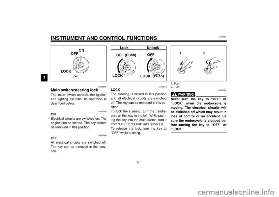
Main switch/steering lockThe main switch controls the ignition
and lighting systems. Its operation is
described below.
EAU00036
ON
Electrical circuits are switched on. The
engine can be started. The key cannot
be removed in this position.
EAU00038
OFF
All electrical circuits are switched off.
The key can be removed in this posi-
tion.
EAU00040
LOCK
The steering is locked in this position
and all electrical circuits are switched
off. The key can be removed in this po-
sition.
To lock the steering, turn the handle-
bars all the way to the left. While push-
ing the key into the main switch, turn it
from “OFF” to “LOCK” and remove it.
To release the lock, turn the key to
“OFF” while pushing.
EW000016
WARNING
@ Never turn the key to “OFF” or
“LOCK” when the motorcycle is
moving. The electrical circuits will
be switched off which may result in
loss of control or an accident. Be
sure the motorcycle is stopped be-
fore turning the key to “OFF” or
“LOCK”. @1. Push
2. Turn
Page 18 of 97
INSTRUMENT AND CONTROL FUNCTIONS
3-4
3
EAU00071
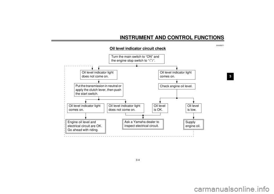
Oil level indicator circuit check
CB-48E
Turn the main switch to “ON” and
the engine stop switch to “ ”.
Oil level indicator light
does not come on.
Oil level indicator light
comes on.Check engine oil level.
Oil level indicator light
comes on.
Oil level indicator light
does not come on.
Engine oil level and
electrical circuit are OK.
Go ahead with riding.
Put the transmission in neutral or
apply the clutch lever, then push
the start switch.
Oil level
is OK.
Supply
engine oil.Oil level
is low.
Ask a Yamaha dealer to
inspect electrical circuit.
Page 19 of 97
INSTRUMENT AND CONTROL FUNCTIONS
3-5
3
EAU00085
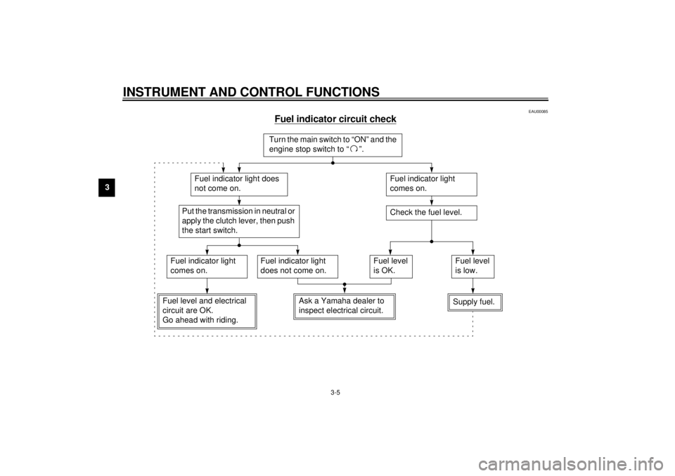
Fuel indicator circuit check
CB-46E
Turn the main switch to “ON” and the
engine stop switch to “ ”.
Fuel indicator light does
not come on.
Fuel indicator light
comes on.Check the fuel level.
Fuel indicator light
comes on.
Fuel indicator light
does not come on.
Fuel level and electrical
circuit are OK.
Go ahead with riding.
Put the transmission in neutral or
apply the clutch lever, then push
the start switch.
Fuel level
is OK.
Supply fuel.Fuel level
is low.
Ask a Yamaha dealer to
inspect electrical circuit.
Page 23 of 97
INSTRUMENT AND CONTROL FUNCTIONS
3-9
3
EAU00118
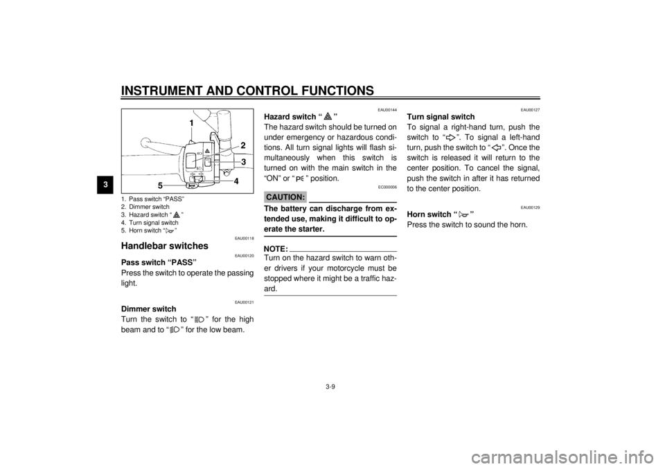
Handlebar switches
EAU00120
Pass switch “PASS”
Press the switch to operate the passing
light.
EAU00121
Dimmer switch
Turn the switch to “ ” for the high
beam and to “ ” for the low beam.
EAU00144
Hazard switch “ ”
The hazard switch should be turned on
under emergency or hazardous condi-
tions. All turn signal lights will flash si-
multaneously when this switch is
turned on with the main switch in the
“ON” or “ ” position.
EC000006
CAUTION:@ The battery can discharge from ex-
tended use, making it difficult to op-
erate the starter. @NOTE:@ Turn on the hazard switch to warn oth-
er drivers if your motorcycle must be
stopped where it might be a traffic haz-
ard. @
EAU00127
Turn signal switch
To signal a right-hand turn, push the
switch to “ ”. To signal a left-hand
turn, push the switch to “ ”. Once the
switch is released it will return to the
center position. To cancel the signal,
push the switch in after it has returned
to the center position.
EAU00129
Horn switch “ ”
Press the switch to sound the horn.
1. Pass switch “PASS”
2. Dimmer switch
3. Hazard switch “ ”
4. Turn signal switch
5. Horn switch “ ”
Page 24 of 97
INSTRUMENT AND CONTROL FUNCTIONS
3-10
3
EAU00138
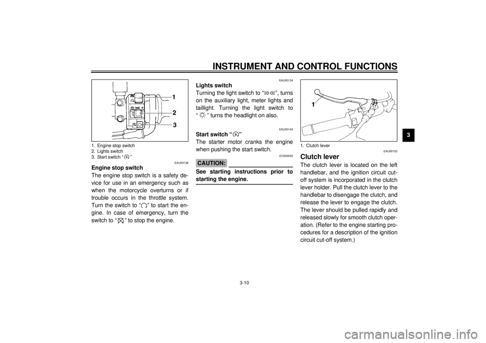
Engine stop switch
The engine stop switch is a safety de-
vice for use in an emergency such as
when the motorcycle overturns or if
trouble occurs in the throttle system.
Turn the switch to “ ” to start the en-
gine. In case of emergency, turn the
switch to “ ” to stop the engine.
EAU00134
Lights switch
Turning the light switch to “ ”, turns
on the auxiliary light, meter lights and
taillight. Turning the light switch to
“ ” turns the headlight on also.
EAU00143
Start switch “ ”
The starter motor cranks the engine
when pushing the start switch.
EC000005
CAUTION:@ See starting instructions prior to
starting the engine. @
EAU00152
Clutch leverThe clutch lever is located on the left
handlebar, and the ignition circuit cut-
off system is incorporated in the clutch
lever holder. Pull the clutch lever to the
handlebar to disengage the clutch, and
release the lever to engage the clutch.
The lever should be pulled rapidly and
released slowly for smooth clutch oper-
ation. (Refer to the engine starting pro-
cedures for a description of the ignition
circuit cut-off system.)
1. Engine stop switch
2. Lights switch
3. Start switch “ ”
1. Clutch lever
Page 32 of 97
INSTRUMENT AND CONTROL FUNCTIONS
3-18
3
EAU00330
SidestandThis model is equipped with an ignition
circuit cut-off system. The motorcycle
must not be ridden when the sidestand
is down. The sidestand is located on
the left side of the frame. (Refer to
page 5-1 for an explanation of this sys-
tem.)
EW000044
WARNING
@ This motorcycle must not be operat-
ed with the sidestand in the down
position. If the stand is not properly
retracted, it could contact the
ground and distract the operator, re-
sulting in a possible loss of control.
Yamaha has designed into this
motorcycle a lockout system to as-
sist the operator in fulfilling the re-
sponsibility of retracting the
sidestand. Please check carefully
the operating instructions listed be-
low and if there is any indication of a
malfunction, return the motorcycle
to a Yamaha dealer immediately for
repair. @
EAU00332
Sidestand/clutch switch
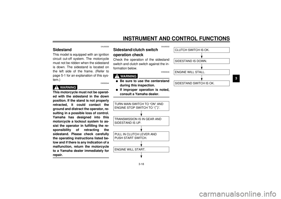
operation checkCheck the operation of the sidestand
switch and clutch switch against the in-
formation below.
EW000046
WARNING
@ l
Be sure to use the centerstand
during this inspection.
l
If improper operation is noted,
consult a Yamaha dealer.
@CD-08E
CD-08E
TURN MAIN SWITCH TO “ON” AND
ENGINE STOP SWITCH TO “ ”.TRANSMISSION IS IN GEAR AND
SIDESTAND IS UP.PULL IN CLUTCH LEVER AND
PUSH START SWITCH.ENGINE WILL START.
SIDESTAND IS DOWN.ENGINE WILL STALL.SIDESTAND SWITCH IS OK.CLUTCH SWITCH IS OK.
Page 40 of 97
OPERATION AND IMPORTANT RIDING POINTS
5-2
5
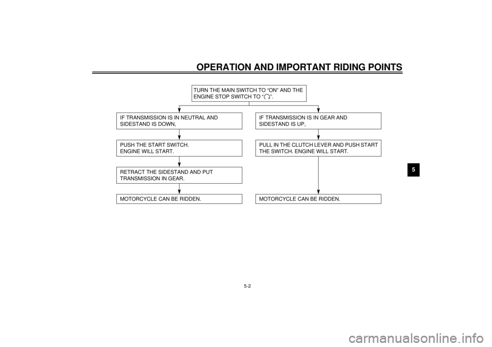
CF-28E
TURN THE MAIN SWITCH TO “ON” AND THE
ENGINE STOP SWITCH TO “ ”.
IF TRANSMISSION IS IN NEUTRAL AND
SIDESTAND IS DOWN,PUSH THE START SWITCH.
ENGINE WILL START.RETRACT THE SIDESTAND AND PUT
TRANSMISSION IN GEAR.
IF TRANSMISSION IS IN GEAR AND
SIDESTAND IS UP,PULL IN THE CLUTCH LEVER AND PUSH START
THE SWITCH. ENGINE WILL START.
MOTORCYCLE CAN BE RIDDEN.
MOTORCYCLE CAN BE RIDDEN.
Page 41 of 97
OPERATION AND IMPORTANT RIDING POINTS
5-3
51. Turn the main switch to “ON” and
the engine stop switch to “ ”.
EC000035
CAUTION:@ If the fuel indicator light comes on,
check the fuel level. If necessary, fill
the tank with fuel. @2. Shift the transmission into neutral.NOTE:@ When the transmission is in neutral, the
neutral indicator light should be on. If
the light does not come on, ask a
Yamaha dealer to inspect it. @3. Turn on the starter (choke) and
completely close the throttle grip.
4. Start the engine by pushing the
start switch.
NOTE:@ If the engine fails to start, release the
start switch, wait a few seconds, then
try again. Each attempt should be as
short as possible to preserve the bat-
tery. Do not crank the engine more
than 10 seconds on any one attempt. @
EC000036
CAUTION:@ The oil level indicator light and fuel
indicator light should come on when
the start switch is pushed and
should go off when the start switch
is released. If the oil level indicator
light flickers or remains on, immedi-
ately stop the engine and check the
engine oil level and for oil leakage. If
necessary, fill the engine with oil
and check to see that the oil level in-
dicator light goes off. If not, consult
a Yamaha dealer. @
5. After starting the engine, move the
starter (choke) to the halfway posi-
tion.NOTE:@ For maximum engine life, never accel-
erate hard with a cold engine! @6. After the engine is warm, turn off
the starter (choke) completely.NOTE:@ The engine is warm when it responds
normally to the throttle with the starter
(choke) turned off. @
Page 56 of 97
PERIODIC MAINTENANCE AND MINOR REPAIR
6-10
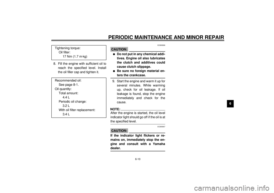
6 8. Fill the engine with sufficient oil to
reach the specified level. Install
the oil filler cap and tighten it.
EC000066
CAUTION:@ l
Do not put in any chemical addi-
tives. Engine oil also lubricates
the clutch and additives could
cause clutch slippage.
l
Be sure no foreign material en-
ters the crankcase.
@9. Start the engine and warm it up for
several minutes. While warming
up, check for oil leakage. If oil
leakage is found, stop the engine
immediately and check for the
cause.NOTE:@ After the engine is started, the oil level
indicator light should go off if the oil is at
the specified level. @
EC000067
CAUTION:@ If the indicator light flickers or re-
mains on, immediately stop the en-
gine and consult with a Yamaha
dealer. @
Tightening torque:
Oil filter:
17 Nm (1.7 m·kg)
Recommended oil:
See page 8-1.
Oil quantity:
Total amount:
4.4 L
Periodic oil change:
3.2 L
With oil filter replacement:
3.4 L
Page 95 of 97
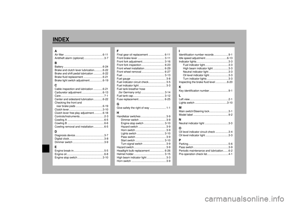
10-INDEXAAir filter .................................................. 6-11
Antitheft alarm (optional) ..........................3-7BBattery ................................................... 6-24
Brake and clutch lever lubrication........... 6-22
Brake and shift pedal lubrication ............ 6-22
Brake fluid replacement ......................... 6-21
Brake light switch adjustment ................. 6-19CCable inspection and lubrication ............ 6-21
Carburetor adjustment ........................... 6-13
Care.........................................................7-1
Center and sidestand lubrication ............ 6-22
Checking the front and
rear brake pads ................................... 6-19
Clutch lever ............................................ 3-10
Clutch lever free play adjustment ........... 6-18
Controls/Instruments ................................2-3
Cowling A ................................................6-5
Cowling B ................................................6-6
Cowling removal and installation ..............6-5DDiagnosis device......................................3-7
Digital clock..............................................3-8
Dimmer switch .........................................3-9EEngine break-in........................................5-5
Engine oil .................................................6-8
Engine stop switch ................................. 3-10
FFinal gear oil replacement ..................... 6-11
Front brake lever ................................... 3-11
Front fork adjustment............................. 3-16
Front fork inspection .............................. 6-23
Front wheel installation .......................... 6-29
Front wheel removal .............................. 6-27
Fuel ....................................................... 3-13
Fuel gauge .............................................. 3-8
Fuel indicator circuit check....................... 3-5
Fuel indicator light ................................... 3-3
Fuel tank breather hose
(for Germany only) .............................. 3-14
Fuel tank cap ......................................... 3-12
Fuse replacement.................................. 6-25GGive safety the right of way ..................... 1-1HHandlebar switches ................................. 3-9
Dimmer switch ................................... 3-9
Engine stop switch ........................... 3-10
Hazard switch .................................... 3-9
Horn switch ........................................ 3-9
Lights switch .................................... 3-10
Pass switch ........................................ 3-9
Start switch ...................................... 3-10
Turn signal switch .............................. 3-9
Hazard switch .......................................... 3-9
Headlight bulb replacement ................... 6-26
Helmet holder ........................................ 3-15
High beam indicator light ......................... 3-3
Horn switch ............................................. 3-9
IIdentification number records ...................9-1
Idle speed adjustment ............................6-13
Indicator lights ..........................................3-3
Fuel indicator light...............................3-3
High beam indicator light ....................3-3
Neutral indicator light ..........................3-3
Oil level indicator light .........................3-3
Turn indicator lights ............................3-3
Inspecting the brake fluid level ...............6-20KKey identification number .........................9-1LLeft view...................................................2-1
Lights switch ..........................................3-10MMain switch/Steering lock .........................3-1
Model label ..............................................9-2NNeutral indicator light ...............................3-3OOil level indicator circuit check .................3-4
Oil level indicator light ..............................3-3PParking.....................................................5-6
Pass switch ..............................................3-9
Periodic maintenance and lubrication .......6-2
Pre-operation check list ............................4-1