key YAMAHA XJR 1300 2000 Owners Manual
[x] Cancel search | Manufacturer: YAMAHA, Model Year: 2000, Model line: XJR 1300, Model: YAMAHA XJR 1300 2000Pages: 95, PDF Size: 2.92 MB
Page 3 of 95

EAU00005
IMPORTANT MANUAL INFORMATIONParticularly important information is distinguished in this manual by the following notations:
The Safety Alert Symbol means ATTENTION! BECOME ALERT! YOUR SAFETY IS
INVOLVED!
WARNING
Failure to follow WARNING instructions could result in severe injury or death
to the
motorcycle operator, a bystander or a person inspecting or repairing the motorcycle.
CAUTION:A CAUTION indicates special precautions that must be taken to avoid damage to the
motorcycle.NOTE:A NOTE provides key information to make procedures easier or clearer.
NOTE:@ l
This manual should be considered a permanent part of this motorcycle and should remain
with it even if the motorcycle is subsequently sold.
l
Yamaha continually seeks advancements in product design and quality. Therefore, while
this manual contains the most current product information available at the time of printing,
there may be minor discrepancies between your motorcycle and this manual. If there is any
question concerning this manual, please consult your Yamaha dealer.
@
Page 15 of 95

3-1
3
EAU00027
3-INSTRUMENT AND CONTROL FUNCTIONS
EAU00029*
Main switch/steering lockThe main switch controls the ignition
and lighting systems. Its operation is
described below.
EAU00036
ON
Electrical circuits are switched on. The
engine can be started. The key cannot
be removed in this position.
EAU00038
OFF
All electrical circuits are switched off.
The key can be removed in this posi-
tion.
EAU00040
LOCK
The steering is locked in this position
and all electrical circuits are switched
off. The key can be removed in this po-
sition.
To lock the steering, turn the handle-
bars all the way to the left. While push-
ing the key into the main switch, turn it
from “OFF” to “LOCK” and remove it.
To release the lock, turn the key to
“OFF” while pushing.
EW000016
WARNING
@ Never turn the key to “OFF” or
“LOCK” when the motorcycle is
moving. The electrical circuits will
be switched off which may result in
loss of control or an accident. Be
sure the motorcycle is stopped be-
fore turning the key to “OFF” or
“LOCK”. @1. Push
2. Turn
Page 16 of 95

INSTRUMENT AND CONTROL FUNCTIONS
3-2
3
EAU01590
(Parking)
The steering is locked in this position,
and the taillight and auxiliary light come
on but all other circuits are off. The key
can be removed in this position.
To use the parking position, first lock
the steering, then turn the key to “ ”.
Do not use this position for an extend-
ed length of time as the battery may
discharge.
EAU00056
Indicator lights
EAU00058
Turn indicator lights “ ” / “ ”
The corresponding indicator flashes
when the turn switch is moved to the
left or right.
EAU00063
High beam indicator light “ ”
This indicator comes on when the
headlight high beam is used.
EAU00061
Neutral indicator light “ ”
This indicator comes on when the
transmission is in neutral.
EAU01313
Oil level indicator light “ ”
This indicator comes on when the oil
level is low. This light circuit can be
checked by the procedure on page 3-3.
EC000000
CAUTION:@ Do not run the motorcycle until you
know it has sufficient engine oil. @NOTE:@ Even if the oil is filled to the specified
level, the indicator light may flicker
when riding on a slope or during sud-
den acceleration or deceleration, but
this is normal. @
1. Left turn indicator light “ ”
2. High beam indicator light “ ”
3. Neutral indicator light “ ”
4. Right turn indicator light “ ”
5. Oil level indicator light “ ”
Page 23 of 95

INSTRUMENT AND CONTROL FUNCTIONS
3-9
3
EAU02935
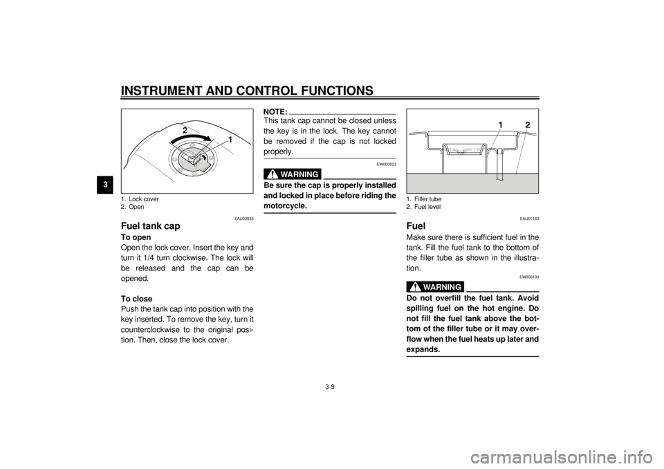
Fuel tank capTo open
Open the lock cover. Insert the key and
turn it 1/4 turn clockwise. The lock will
be released and the cap can be
opened.
To close
Push the tank cap into position with the
key inserted. To remove the key, turn it
counterclockwise to the original posi-
tion. Then, close the lock cover.
NOTE:@ This tank cap cannot be closed unless
the key is in the lock. The key cannot
be removed if the cap is not locked
properly. @
EW000023
WARNING
@ Be sure the cap is properly installed
and locked in place before riding the
motorcycle. @
EAU01183
FuelMake sure there is sufficient fuel in the
tank. Fill the fuel tank to the bottom of
the filler tube as shown in the illustra-
tion.
EW000130
WARNING
@ Do not overfill the fuel tank. Avoid
spilling fuel on the hot engine. Do
not fill the fuel tank above the bot-
tom of the filler tube or it may over-
flow when the fuel heats up later and
expands. @
1. Lock cover
2. Open
1. Filler tube
2. Fuel level
Page 25 of 95

INSTRUMENT AND CONTROL FUNCTIONS
3-11
3
PRI
This stands for “prime”. If the engine
has been allowed to run out of fuel, turn
the lever to the “PRI” position to send
fuel directly to the carburetors. This will
make starting easier. However, be sure
to turn the lever to the “ON” position (or
“RES” if you have not refuelled yet) af-
ter the engine has started.
EAU02976
Starter (choke) “ ”Starting a cold engine requires a richer
air-fuel mixture. A separate starter cir-
cuit supplies this mixture.
Move in direction
a to turn on the
starter (choke).
Move in direction
b to turn off the
starter (choke).
EAU01721
SeatTo remove
Insert the key in the helmet holder lock
and turn it as shown.
1. Arrow mark positioned over “PRI”PRI: priming position
1. Starter (choke) “ ”
1. Open
Page 26 of 95

INSTRUMENT AND CONTROL FUNCTIONS
3-12
3
To install
Insert the projection on the front of the
seat into the holder, then push down
the seat.
NOTE:@ Make sure that the seat is securely fit-
ted. @
EAU00260
Helmet holderTo open the helmet holder, insert the
key in the lock and turn it as shown.
To lock the helmet holder, replace the
holder in its original position.
EW000030
WARNING
@ Never ride with a helmet in the hel-
met holder. The helmet may hit ob-
jects, causing loss of control and
possibly an accident. @
EAU01688
Storage compartmentThis compartment is designed to store
a genuine Yamaha U-LOCK. (Other
locks may not fit.) Be sure the lock is
fastened securely with the straps when
storing it in the compartment.
To prevent losing the straps, be sure to
secure them even when a U-LOCK is
not being stored in the compartment.
When storing this Owner’s manual or
other documents in the compartment,
be sure to put them in a vinyl bag so
they do not get wet. When washing the
motorcycle, be careful not to flood this
compartment with water.
1. Projection
2. Seat holder
1. Open
1. U-LOCK
2. Strap (´ 2)
Page 42 of 95

OPERATION AND IMPORTANT RIDING POINTS
5-6
5
EAU01329*
0 ~ 1,000 km
Avoid operation above 4,000 r/min.
1,000 ~ 1,600 km
Avoid cruising speeds in excess of
5,000 r/min.
EC000052*
CAUTION:@ After 1,000 km of operation, be sure
to replace the engine oil and oil filter
element. @1,600 km and beyond
Proceed with normal riding.
EC000053*
CAUTION:@ l
Never let the engine speed enter
the red zone.
l
If any engine trouble should oc-
cur during the break-in period,
consult a Yamaha dealer imme-
diately.
@
EAU00460
ParkingWhen parking the motorcycle, stop the
engine and remove the ignition key.
EW000058
WARNING
@ The exhaust system is hot. Park the
motorcycle in a place where pedes-
trians or children are not likely to
touch the motorcycle. Do not park
the motorcycle on a slope or soft
ground; the motorcycle may over-
turn.@
Page 90 of 95

9
CONSUMER INFORMATION
Identification number records ............................................................. 9-1
Key identification number ................................................................... 9-1
Vehicle identification number.............................................................. 9-1
Model label ......................................................................................... 9-2
Page 91 of 95

9-1
9
EAU01039
9-CONSUMER INFORMATION
EAU02944
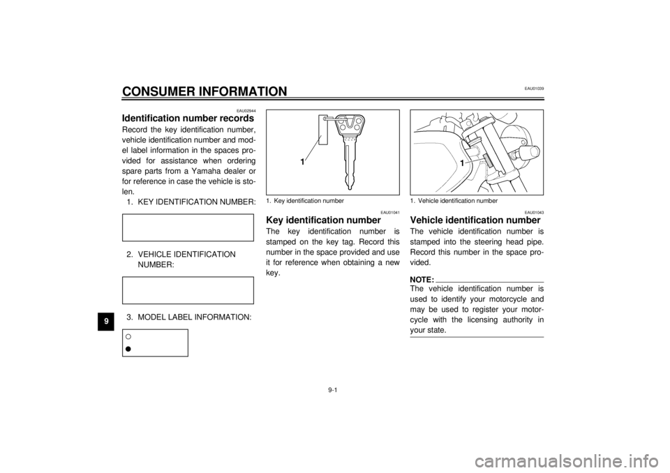
Identification number recordsRecord the key identification number,
vehicle identification number and mod-
el label information in the spaces pro-
vided for assistance when ordering
spare parts from a Yamaha dealer or
for reference in case the vehicle is sto-
len.
1. KEY IDENTIFICATION NUMBER:CA-02E2. VEHICLE IDENTIFICATION
NUMBER:CA-02E3. MODEL LABEL INFORMATION:CA-01EEAU01041
Key identification numberThe key identification number is
stamped on the key tag. Record this
number in the space provided and use
it for reference when obtaining a new
key.
EAU01043
Vehicle identification numberThe vehicle identification number is
stamped into the steering head pipe.
Record this number in the space pro-
vided.NOTE:@ The vehicle identification number is
used to identify your motorcycle and
may be used to register your motor-
cycle with the licensing authority in
your state. @
1. Key identification number
1. Vehicle identification number
Page 93 of 95

10-INDEXAAir filter .................................................. 6-10
Antitheft alarm (optional) ..........................3-4BBattery ................................................... 6-23
Brake and clutch lever lubrication........... 6-21
Brake and shift pedal lubrication ............ 6-21
Brake fluid replacement ......................... 6-19
Brake light switch adjustment ................. 6-17CCable inspection and lubrication ............ 6-20
Carburetor adjustment ........................... 6-11
Care.........................................................7-1
Center and sidestand lubrication ............ 6-22
Checking the front and
rear brake pads ................................... 6-17
Clutch lever ..............................................3-7
Controls/Instruments ................................2-3DDimmer switch .........................................3-5
Drive chain lubrication ............................ 6-20
Drive chain slack adjustment.................. 6-19
Drive chain slack check.......................... 6-19EEngine break-in........................................5-5
Engine oil .................................................6-7
Engine stop switch ...................................3-6FFront brake lever ......................................3-8
Front fork adjustment ............................. 3-13
Front fork inspection .............................. 6-22
Front wheel installation .......................... 6-29
Front wheel removal .............................. 6-28
Fuel ......................................................... 3-9
Fuel cock ............................................... 3-10
Fuel gauge .............................................. 3-5
Fuel tank cap ........................................... 3-9
Fuse replacement.................................. 6-25GGive safety the right of way ..................... 1-1HHandlebar switches ................................. 3-5
Dimmer switch ................................... 3-5
Engine stop switch ............................. 3-6
Horn switch ........................................ 3-5
Lights switch ...................................... 3-6
Pass switch ........................................ 3-5
Start switch ........................................ 3-6
Turn signal switch .............................. 3-5
Headlight bulb replacement ................... 6-25
Helmet holder ........................................ 3-12
High beam indicator light ......................... 3-2
Horn switch ............................................. 3-5IIdentification number records................... 9-1
Idle speed adjustment ........................... 6-11
Indicator lights ......................................... 3-2
High beam indicator light .................... 3-2
Neutral indicator light.......................... 3-2
Oil level indicator light ........................ 3-2
Turn indicator lights ............................ 3-2
Inspecting the brake fluid level............... 6-18
KKey identification number .........................9-1LLeft view...................................................2-1
Lights switch ............................................3-6
Luggage strap holders ...........................3-15MMain switch/Steering lock .........................3-1
Model label ..............................................9-2NNeutral indicator light ...............................3-2OOil level indicator circuit check .................3-3
Oil level indicator light ..............................3-2PPanel A ....................................................6-5
Panel removal and installation..................6-5
Parking.....................................................5-6
Pass switch ..............................................3-5
Periodic maintenance and lubrication .......6-2
Pre-operation check list ............................4-1RRear brake pedal .....................................3-8
Rear brake pedal height adjustment.......6-16
Rear shock absorber adjustment............3-13
Rear wheel installation ...........................6-31
Rear wheel removal ...............................6-30
Recommended shift points
(for Switzerland only) .............................5-5
Right view ................................................2-2