fuel cap YAMAHA XJR 1300 2001 Owners Manual
[x] Cancel search | Manufacturer: YAMAHA, Model Year: 2001, Model line: XJR 1300, Model: YAMAHA XJR 1300 2001Pages: 100, PDF Size: 11.75 MB
Page 15 of 100

INSTRUMENT AND CONTROL FUNCTIONS
3
Main switch/steering lock .................................................................. 3-1
Indicator and warning lights .............................................................. 3-2
Speedometer unit .............................................................................. 3-3
Tachometer ....................................................................................... 3-3
Anti-theft alarm (optional) .................................................................. 3-3
Fuel gauge ........................................................................................ 3-4
Handlebar switches ........................................................................... 3-4
Clutch lever ....................................................................................... 3-5
Shift pedal ......................................................................................... 3-6
Brake lever ........................................................................................ 3-7
Brake pedal ....................................................................................... 3-7
Fuel tank cap ..................................................................................... 3-8
Fuel ................................................................................................... 3-9
Fuel cock ........................................................................................... 3-9
Starter (choke) lever ........................................................................ 3-10
Seat ................................................................................................. 3-11
Helmet holder .................................................................................. 3-11
Storage compartment ..................................................................... 3-12
Adjusting the front fork .................................................................... 3-12
Adjusting the shock absorber assemblies
....................................... 3-13
Luggage strap holders .................................................................... 3-15
Sidestand ........................................................................................ 3-15
Ignition circuit cut-off system ........................................................... 3-16
E_5ea.book Page 1 Wednesday, October 4, 2000 4:14 PM
Page 23 of 100

INSTRUMENT AND CONTROL FUNCTIONS
3-8
3
EAU02935
Fuel tank cap To open the fuel tank cap
Open the fuel tank cap lock cover, in-
sert the key into the lock, and then turn
it 1/4 turn clockwise. The lock will be re-
leased and the fuel tank cap can be
opened.
To close the fuel tank cap
1. Push the fuel tank cap into posi-
tion with the key inserted in the
lock. 2. Turn the key counterclockwise to
the original position, remove it,
and then close the lock cover.
NOTE:_ The fuel tank cap cannot be closed un-
less the key is in the lock. In addition,
the key cannot be removed if the cap is
not properly closed and locked. _
EWA00025
WARNING
_ Make sure that the fuel tank cap is
properly closed before riding. _
1. Fuel tank cap lock cover
2. Unlock.
E_5ea.book Page 8 Wednesday, October 4, 2000 4:14 PM
Page 24 of 100

INSTRUMENT AND CONTROL FUNCTIONS
3-9
3
EAU03754
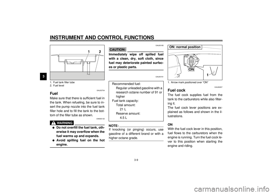
Fuel Make sure that there is sufficient fuel in
the tank. When refueling, be sure to in-
sert the pump nozzle into the fuel tank
filler hole and to fill the tank to the bot-
tom of the filler tube as shown.
EW000130
WARNING
_ l
Do not overfill the fuel tank, oth-
erwise it may overflow when the
fuel warms up and expands.
l
Avoid spilling fuel on the hot
engine.
_
EAU00185
CAUTION:_ Immediately wipe off spilled fuel
with a clean, dry, soft cloth, since
fuel may deteriorate painted surfac-
es or plastic parts. _
EAU00191
NOTE:_ If knocking (or pinging) occurs, use
gasoline of a different brand or with a
higher octane grade. _
EAU00207
Fuel cock The fuel cock supplies fuel from the
tank to the carburetors while also filter-
ing it.
The fuel cock lever positions are ex-
plained as follows and shown in the il-
lustrations.
ON
With the fuel cock lever in this position,
fuel flows to the carburetors when the
engine is running. Turn the fuel cock le-
ver to this position when starting the
engine and riding.
1. Fuel tank filler tube
2. Fuel level
Recommended fuel:
Regular unleaded gasoline with a
research octane number of 91 or
higher
Fuel tank capacity:
Total amount:
21 L
Reserve amount:
4.5 L
1. Arrow mark positioned over “ON”ON: normal position
E_5ea.book Page 9 Wednesday, October 4, 2000 4:14 PM
Page 85 of 100

MOTORCYCLE CARE AND STORAGE
7-4
7
Storage Short-term
Always store your motorcycle in a cool,
dry place and, if necessary, protect it
against dust with a porous cover.
ECA00014
CAUTION:_ l
Storing the motorcycle in a
poorly ventilated room or cover-
ing it with a tarp, while it is still
wet, will allow water and humid-
ity to seep in and cause rust.
l
To prevent corrosion, avoid
damp cellars, stables (because
of the presence of ammonia)
and areas where strong chemi-
cals are stored.
_
Long-term
Before storing your motorcycle for
several months:
1. Follow all the instructions in the
“Care” section of this chapter.
2. For motorcycles equipped with a
fuel cock that has an “OFF” posi-
tion: Turn the fuel cock lever to
“OFF”.
3. Drain the carburetor float chamber
by loosening the drain bolt; this will
prevent fuel deposits from building
up. Pour the drained fuel into the
fuel tank.
4. Fill up the fuel tank and add fuel
stabilizer (if available) to prevent
the fuel tank from rusting and the
fuel from deteriorating.
5. Perform the following steps to pro-
tect the cylinders, piston rings, etc.
from corrosion.a. Remove the spark plug caps and
spark plugs.
b. Pour a teaspoonful of engine oil
into each spark plug bore.
c. Install the spark plug caps onto the
spark plugs, and then place the
spark plugs on the cylinder head
so that the electrodes are ground-
ed. (This will limit sparking during
the next step.)
d. Turn the engine over several times
with the starter. (This will coat the
cylinder walls with oil.)
e. Remove the spark plug caps from
the spark plugs, and then install
the spark plugs and the spark plug
caps.
EWA00003
WARNING
_ To prevent damage or injury from
sparking, make sure to ground the
spark plug electrodes while turning
the engine over. _
E_5ea.book Page 4 Wednesday, October 4, 2000 4:14 PM
Page 89 of 100

SPECIFICATIONS
8-2
8
Fuel
Type Regular unleaded gasoline
Fuel tank capacity 21 L
Fuel reserve amount 4.5 L
Carburetor
Manufacturer MIKUNI
Model ´ quantity BS36 ´ 4
Spark plug
Manufacturer/model NGK / DPR8EA-9 or
DENSO / X24EPR-U9
Gap 0.8–0.9 mm
Clutch typeWet, multiple-disc
Transmission
Primary reduction system Spur gear
Primary reduction ratio 1.750
Secondary reduction system Chain drive
Secondary reduction ratio 2.235
Number of drive chain
sprocket teeth (front/rear) 17/38
Transmission type Constant-mesh 5-speed
Operation Left foot
Gear ratio
1st 2.857
2nd 2.000
3rd 1.5714th 1.292
5th 1.115
Chassis
Frame type Double cradle
Caster angle 25.5 °
Trail 100 mm
Tires
Front
Type Tubeless tire
Size 120/70ZR17 (58W)
Manufacturer/model Bridgestone / BT57F
Dunlop / D207F
Michelin / MACADAM90X
Rear
Type Tubeless tire
Size 180/55ZR17 (73W)
Manufacturer/model Bridgestone / BT57R
Dunlop / D207
Michelin / MACADAM90X
Maximum load* 207 kg
Tire air pressure
(measured on cold tires)
Up to 90 kg*
Front 250 kPa (2.50 kg/cm
2, 2.50 bar)
Rear 250 kPa (2.50 kg/cm2, 2.50 bar)
E_5ea.book Page 2 Wednesday, October 4, 2000 4:14 PM
Page 96 of 100

INDEXAAir filter element, cleaning ...................... 6-11
Anti-theft alarm ........................................3-3BBattery ................................................... 6-27
Brake and clutch levers, checking and
lubricating ............................................ 6-24
Brake and shift pedals, checking and
lubricating ............................................ 6-24
Brake fluid, changing ............................. 6-20
Brake fluid level, checking...................... 6-19
Brake lever...............................................3-7
Brake light switch (rear), adjusting ......... 6-18
Brake pads, checking............................. 6-19
Brake pedal..............................................3-7
Brake pedal position, adjusting .............. 6-17CCables, checking and lubricating............ 6-23
Carburetors, adjusting............................ 6-12
Care.........................................................7-1
Centerstand and sidestand, checking
and lubricating ..................................... 6-25
Clutch lever ..............................................3-5
Conversion table ......................................8-5DDimmer switch .........................................3-4
Drive chain, lubricating ........................... 6-22
Drive chain slack .................................... 6-21
Adjusting .......................................... 6-21
Checking .......................................... 6-21
EEngine break-in ....................................... 5-4
Engine oil and oil filter element ................ 6-7
Engine stop switch................................... 3-5FFront fork, adjusting ............................... 3-12
Front fork, checking ............................... 6-25
Fuel ......................................................... 3-9
Fuel cock ................................................. 3-9
Fuel consumption, tips for reducing ......... 5-4
Fuel gauge .............................................. 3-4
Fuel tank cap ........................................... 3-8
Fuses, replacing .................................... 6-29HHandlebar switches ................................. 3-4
Headlight bulb, replacing ....................... 6-29
Helmet holder ........................................ 3-11
High beam indicator light ......................... 3-2
Horn switch ............................................. 3-4IIdentification numbers ............................. 9-1
Idling speed, adjusting ........................... 6-13
Ignition circuit cut-off system.................. 3-16
Indicator and warning lights ..................... 3-2KKey identification number ........................ 9-1LLight switch.............................................. 3-5
Luggage strap holders ........................... 3-15
MMain switch/steering lock .........................3-1
Model label ..............................................9-2NNeutral indicator light ...............................3-2OOil level warning light ...............................3-2PPanel, removing and installing..................6-5
Parking.....................................................5-5
Part locations ...........................................2-1
Pass switch ..............................................3-4
Periodic maintenance and lubrication
chart ......................................................6-2
Pre-operation check list ............................4-1SSafety information ....................................1-1
Seat .......................................................3-11
Shifting .....................................................5-3
Shift pedal ................................................3-6
Shift points (for Switzerland only) .............5-3
Shock absorber assemblies,
adjusting ............................................... 3-13
Sidestand ...............................................3-15
Spark plugs, checking ..............................6-6
Specifications ...........................................8-1
Speedometer unit.....................................3-3
Starter (choke) lever...............................3-10
Starting a cold engine ..............................5-1
Starting a warm engine ............................5-2
Start switch ..............................................3-5
E_5ea.book Page 1 Wednesday, October 4, 2000 4:14 PM