oil level YAMAHA XJR 1300 2013 Owners Manual
[x] Cancel search | Manufacturer: YAMAHA, Model Year: 2013, Model line: XJR 1300, Model: YAMAHA XJR 1300 2013Pages: 98, PDF Size: 2.34 MB
Page 6 of 98

TABLE OF CONTENTSSAFETY INFORMATION ..................1-1
DESCRIPTION ..................................2-1
Left view ..........................................2-1
Right view ........................................2-2
Controls and instruments.................2-3
INSTRUMENT AND CONTROL
FUNCTIONS .......................................3-1
Immobilizer system .........................3-1
Main switch/steering lock ................3-2
Indicator lights and warning lights ............................................3-4
Speedometer ..................................3-5
Tachometer ....................................3-5
Multi-function display ......................3-6
Anti-theft alarm (optional) ...............3-9
Handlebar switches ........................3-9
Clutch lever ...................................3-10
Shift pedal .....................................3-11
Brake lever ...................................3-11
Brake pedal ..................................3-12
Fuel tank cap ................................3-12
Fuel ...............................................3-13
Fuel tank breather hose and overflow hose ............................3-14
Catalytic converters ......................3-15
Seat ..............................................3-15
Helmet holder ...............................3-16
Storage compartment ...................3-16
Adjusting the front fork ..................3-17 Adjusting the shock absorber
assembly ................................... 3-19
Luggage strap holders ................. 3-21
EXUP system ............................... 3-22
Sidestand ..................................... 3-22
Ignition circuit cut-off system ........ 3-23
FOR YOUR SAFETY –
PRE-OPERATION CHECKS ............. 4-1
OPERATION AND IMPORTANT
RIDING POINTS ................................. 5-1
Starting the engine ......................... 5-1
Shifting ........................................... 5-2
Tips for reducing fuel consumption ............................... 5-3
Engine break-in .............................. 5-3
Parking ........................................... 5-4
PERIODIC MAINTENANCE AND
ADJUSTMENT ................................... 6-1
Owner’s tool kit ............................... 6-2
Periodic maintenance chart for the emission control system ............. 6-3
General maintenance and lubrication chart .......................... 6-4
Removing and installing panels ..... 6-8
Checking the spark plugs ............... 6-9
Engine oil and oil filter element .... 6-10
Replacing the air filter element and cleaning the check hose .... 6-13 Checking the throttle grip free
play ........................................... 6-14
Valve clearance ........................... 6-15
Tires ............................................. 6-15
Cast wheels ................................. 6-18
Clutch lever .................................. 6-18
Checking the brake lever free play ........................................... 6-18
Brake light switches ..................... 6-19
Checking the front and rear brake pads .......................................... 6-20
Checking the brake and clutch fluid levels ................................. 6-20
Changing the brake and clutch
fluids ......................................... 6-22
Drive chain slack .......................... 6-22
Cleaning and lubricating the drive chain ......................................... 6-23
Checking and lubricating the cables ....................................... 6-24
Checking and lubricating the throttle grip and cable ............... 6-24
Checking and lubricating the
brake and shift pedals .............. 6-25
Checking and lubricating the brake and clutch levers ............ 6-25
Checking and lubricating the centerstand and sidestand ....... 6-26
Lubricating the swingarm
pivots ........................................ 6-27
Checking the front fork ................. 6-27U5WME9E0.book Page 1 Friday, December 7, 2012 3:50 PM
Page 14 of 98
DESCRIPTION
2-2
2
EAU10420
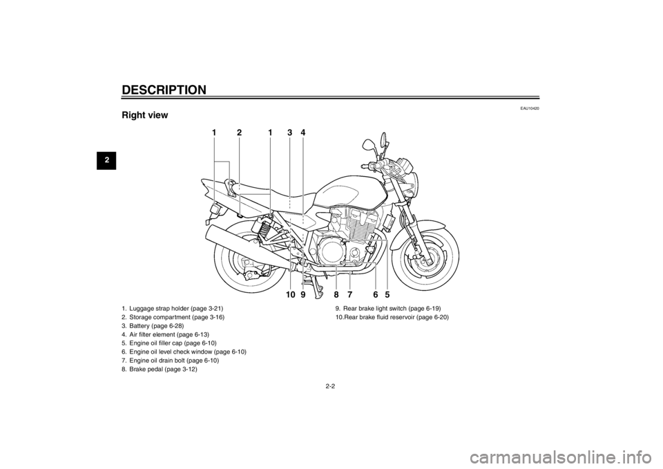
Right view
1
2
3
4
5
6
8
1
7
9
10
1. Luggage strap holder (page 3-21)
2. Storage compartment (page 3-16)
3. Battery (page 6-28)
4. Air filter element (page 6-13)
5. Engine oil filler cap (page 6-10)
6. Engine oil level check window (page 6-10)
7. Engine oil drain bolt (page 6-10)
8. Brake pedal (page 3-12)9. Rear brake light switch (page 6-19)
10.Rear brake fluid reservoir (page 6-20)U5WME9E0.book Page 2 Friday, December 7, 2012 3:50 PM
Page 19 of 98
INSTRUMENT AND CONTROL FUNCTIONS
3-4
3
EAU49392
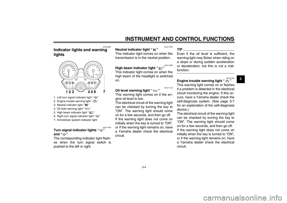
Indicator lights and warning
lights
EAU11030
Turn signal indicator lights “ ”
and “ ”
The corresponding indicator light flash-
es when the turn signal switch is
pushed to the left or right.
EAU11060
Neutral indicator light “ ”
This indicator light comes on when the
transmission is in the neutral position.
EAU11080
High beam indicator light “ ”
This indicator light comes on when the
high beam of the headlight is switched
on.
EAU11123
Oil level warning light “ ”
This warning light comes on if the en-
gine oil level is low.
The electrical circuit of the warning light
can be checked by turning the key to
“ON”. The warning light should come
on for a few seconds, and then go off.
If the warning light does not come on
initially when the key is turned to “ON”,
or if the warning light remains on, have
a Yamaha dealer check the electrical
circuit.
TIPEven if the oil level is sufficient, the
warning light may flicker when riding on
a slope or during sudden acceleration
or deceleration, but this is not a mal-
function.
EAU11534
Engine trouble warning light “ ”
This warning light comes on or flashes
if a problem is detected in the electrical
circuit monitoring the engine. If this oc-
curs, have a Yamaha dealer check the
self-diagnosis system. (See page 3-7
for an explanation of the self-diagnosis
device.)
The electrical circuit of the warning light
can be checked by turning the key to
“ON”. The warning light should come
on for a few seconds, and then go off.
If the warning light does not come on
initially when the key is turned to “ON”,
or if the warning light remains on, have
a Yamaha dealer check the electrical
circuit.
1. Left turn signal indicator light “ ”
2. Engine trouble warning light “ ”
3. Neutral indicator light “ ”
4. Oil level warning light “ ”
5. High beam indicator light “ ”
6. Right turn signal indicator light “ ”
7. Immobilizer system indicator light
U5WME9E0.book Page 4 Friday, December 7, 2012 3:50 PM
Page 40 of 98
FOR YOUR SAFETY – PRE-OPERATION CHECKS
4-1
4
EAU15597
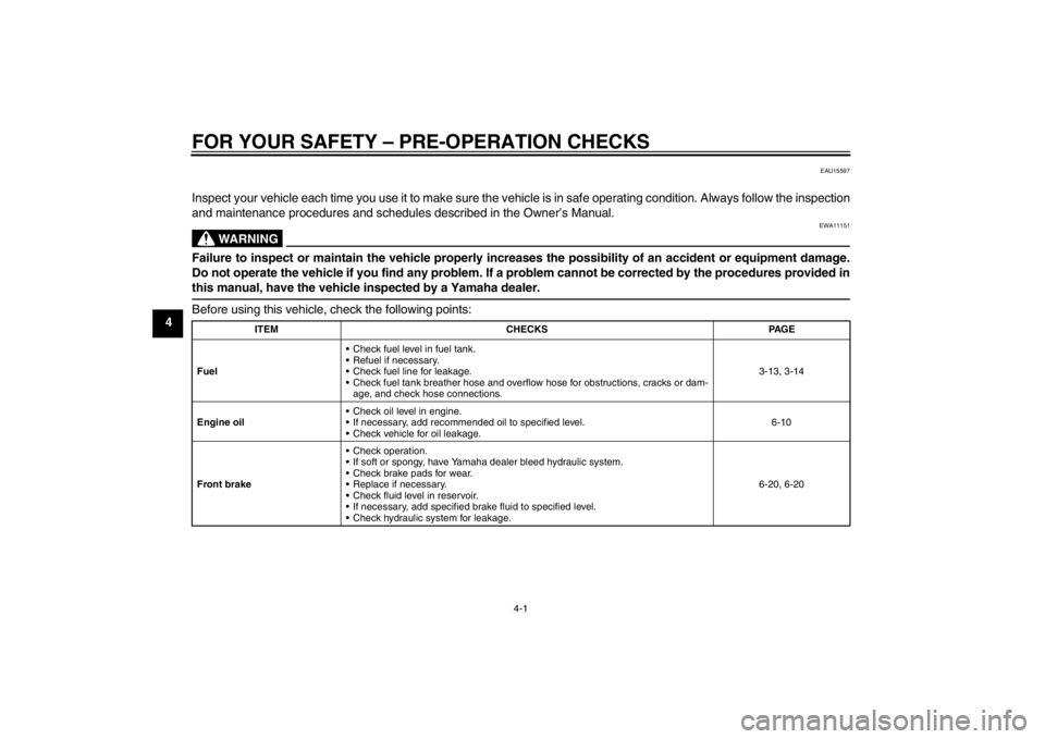
Inspect your vehicle each time you use it to make sure the vehicle is in safe operating condition. Always follow the inspection
and maintenance procedures and schedules described in the Owner’s Manual.
WARNING
EWA11151
Failure to inspect or maintain the vehicle properly increases the possibility of an accident or equipment damage.
Do not operate the vehicle if you find any problem. If a problem cannot be corrected by the procedures provided in
this manual, have the vehicle inspected by a Yamaha dealer.Before using this vehicle, check the following points:
ITEMCHECKS PAGE
Fuel Check fuel level in fuel tank.
Refuel if necessary.
Check fuel line for leakage.
Check fuel tank breather hose and overflow
hose for obstructions, cracks or dam-
age, and check hose connections. 3-13, 3-14
Engine oil Check oil level in engine.
If necessary, add recommended oil to specified level.
Check vehicle for oil leakage. 6-10
Front brake Check operation.
If soft or spongy, have Yamaha dealer bleed hydraulic system.
Check brake pads for wear.
Replace if necessary.
Check fluid level in reservoir.
If necessary, add specified brake fluid to specified level.
Check hydraulic system for leakage. 6-20, 6-20
U5WME9E0.book Page 1 Friday, December 7, 2012 3:50 PM
Page 43 of 98

OPERATION AND IMPORTANT RIDING POINTS
5-1
5
EAU15951
Read the Owner’s Manual carefully to
become familiar with all controls. If
there is a control or function you do not
understand, ask your Yamaha dealer.
WARNING
EWA10271
Failure to familiarize yourself with
the controls can lead to loss of con-
trol, which could cause an accident
or injury.
EAU48710
TIPThis model is equipped with:●
a lean angle sensor to stop the en-
gine in case of a turnover. In this
case, the multi-function display in-
dicates error code 30, but this is
not a malfunction. Turn the key to
“OFF” and then to “ON” to clear the
error code. Failing to do so will pre-
vent the engine from starting even
though the engine will crank when
pushing the start switch.
●
an engine auto-stop system. The
engine stops automatically if left
idling for 20 minutes. If the engine
stops, simply push the start switch
to restart the engine.
EAU33729
Starting the engine In order for the ignition circuit cut-off
system to enable starting, one of the
following conditions must be met:●
The transmission is in the neutral
position.
●
The transmission is in gear with
the clutch lever pulled and the
sidestand up.
See page 3-23 for more informa-
tion.
1. Turn the key to “ON” and make sure that the engine stop switch is
set to “ ”.
The following warning lights and
indicator light should come on for a
few seconds, then go off.●
Oil level warning light
●
Engine trouble warning light
●
Immobilizer system indicator
light
NOTICE
ECA11833
If a warning or indicator light does
not come on initially when the key is
turned to “ON”, or if a warning or in-
U5WME9E0.book Page 1 Friday, December 7, 2012 3:50 PM
Page 52 of 98
PERIODIC MAINTENANCE AND ADJUSTMENT
6-6
6
EAU36772
TIP●
Air filter This model’s air filter is equipped with a disposable oil-coated paper element, which must not be cleaned with com- pressed air to avoid damaging it.
The air filter element needs to be replaced more frequently when riding in unusually wet or dusty areas.
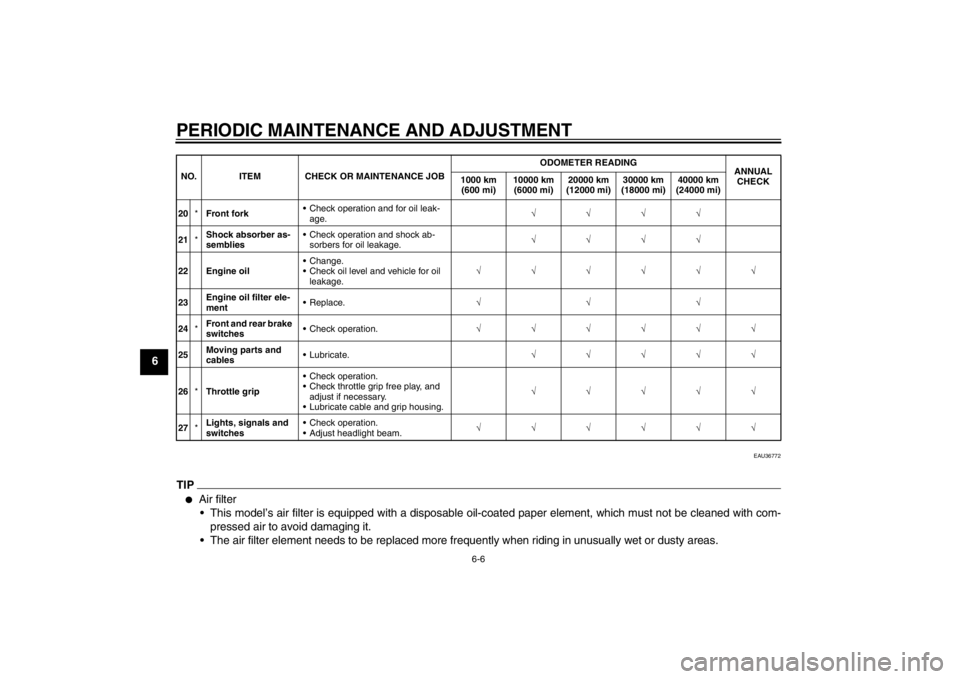
20 *Front fork Check operation and for oil leak-
age. √√√√
21 *Shock absorber as-
semblies Check operation and shock ab-
sorbers for oil leakage. √√√√
22 Engine oil Change.
Check oil level and vehicle for oil
leakage. √√√√√√
23 Engine oil filter ele-
ment Replace.
√√√
24 *Front and rear brake
switches
Check operation.
√√√√√√
25 Moving parts and
cables Lubricate.
√√√√√
26 *Throttle grip Check operation.
Check throttle grip free play, and
adjust if necessary.
Lubricate cable and grip housing. √√√√√
27 *Lights, signals and
switches Check operation.
Adjust headlight beam.
√√√√√√
NO. ITEM CHECK OR MAINTENANCE JOB
ODOMETER READING
ANNUAL
CHECK
1000 km
(600 mi) 10000 km
(6000 mi) 20000 km
(12000 mi) 30000 km
(18000 mi) 40000 km
(24000 mi)U5WME9E0.book Page 6 Friday, December 7, 2012 3:50 PM
Page 56 of 98
PERIODIC MAINTENANCE AND ADJUSTMENT
6-10
63. Check each spark plug for elec-
trode erosion and excessive car-
bon or other deposits, and replace
it if necessary.
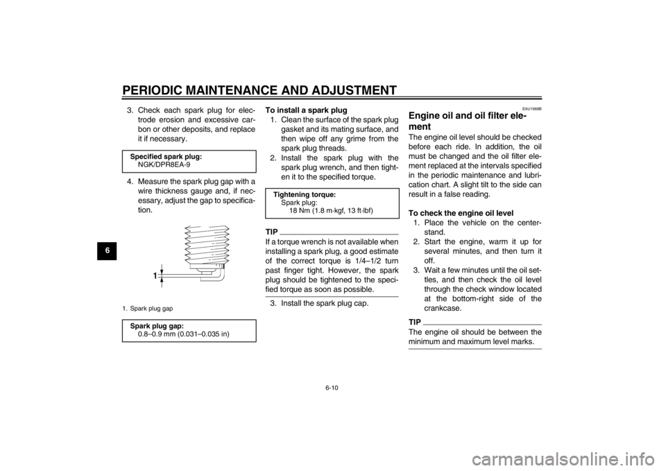
4. Measure the spark plug gap with a wire thickness gauge and, if nec-
essary, adjust the gap to specifica-
tion. To install a spark plug
1. Clean the surface of the spark plug gasket and its mating surface, and
then wipe off any grime from the
spark plug threads.
2. Install the spark plug with the spark plug wrench, and then tight-
en it to the specified torque.
TIPIf a torque wrench is not available when
installing a spark plug, a good estimate
of the correct torque is 1/4–1/2 turn
past finger tight. However, the spark
plug should be tightened to the speci-
fied torque as soon as possible.3. Install the spark plug cap.
EAU1969B
Engine oil and oil filter ele-
ment The engine oil level should be checked
before each ride. In addition, the oil
must be changed and the oil filter ele-
ment replaced at the intervals specified
in the periodic maintenance and lubri-
cation chart. A slight tilt to the side can
result in a false reading.
To check the engine oil level1. Place the vehicle on the center- stand.
2. Start the engine, warm it up for several minutes, and then turn it
off.
3. Wait a few minutes until the oil set- tles, and then check the oil level
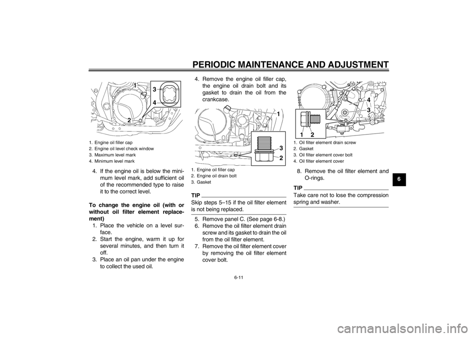
through the check window located
at the bottom-right side of the
crankcase.TIPThe engine oil should be between the
minimum and maximum level marks.
Specified spark plug:NGK/DPR8EA-91. Spark plug gapSpark plug gap:0.8–0.9 mm (0.031–0.035 in)
Tightening torque:
Spark plug:18 Nm (1.8 m·kgf, 13 ft·lbf)
U5WME9E0.book Page 10 Friday, December 7, 2012 3:50 PM
Page 57 of 98
PERIODIC MAINTENANCE AND ADJUSTMENT
6-11
6
4. If the engine oil is below the mini-
mum level mark, add sufficient oil
of the recommended type to raise
it to the correct level.
To change the engine oil (with or
without oil filter element replace-
ment) 1. Place the vehicle on a level sur- face.
2. Start the engine, warm it up for several minutes, and then turn it
off.
3. Place an oil pan under the engine to collect the used oil. 4. Remove the engine oil filler cap,
the engine oil drain bolt and its
gasket to drain the oil from the
crankcase.
TIPSkip steps 5–15 if the oil filter element
is not being replaced.5. Remove panel C. (See page 6-8.)
6. Remove the oil filter element drainscrew and its gasket to drain the oil
from the oil filter element.
7. Remove the oil filter element cover by removing the oil filter element
cover bolt. 8. Remove the oil filter element and
O-rings.
TIPTake care not to lose the compression
spring and washer.
1. Engine oil filler cap
2. Engine oil level check window
3. Maximum level mark
4. Minimum level mark
3
4
1. Engine oil filler cap
2. Engine oil drain bolt
3. Gasket
231
1. Oil filter element drain screw
2. Gasket
3. Oil filter element cover bolt
4. Oil filter element cover
1
2
43
U5WME9E0.book Page 11 Friday, December 7, 2012 3:50 PM
Page 59 of 98
PERIODIC MAINTENANCE AND ADJUSTMENT
6-13
6
TIPBe sure to wipe off spilled oil on any
parts after the engine and exhaust sys-
tem have cooled down.NOTICE
ECA11620
●
In order to prevent clutch slip-
page (since the engine oil also
lubricates the clutch), do not
mix any chemical additives. Do
not use oils with a diesel speci-
fication of “CD” or oils of a high-
er quality than specified. In
addition, do not use oils labeled
“ENERGY CONSERVING II” or
higher.
●
Make sure that no foreign mate-
rial enters the crankcase.
18. Start the engine, and then let it idlefor several minutes while checking
it for oil leakage. If oil is leaking, im-
mediately turn the engine off and
check for the cause.
TIPAfter the engine is started, the engine
oil level warning light should go off if the
oil level is sufficient.NOTICE
ECA10401
If the oil level warning light flickers
or remains on even if the oil level is
correct, immediately turn the engine
off and have a Yamaha dealer check
the vehicle.19. Turn the engine off, and thencheck the oil level and correct it if
necessary.
EAU43451
Replacing the air filter element
and cleaning the check hose The air filter element should be re-
placed at the intervals specified in the
periodic maintenance and lubrication
chart. Replace the air filter element
more frequently if you are riding in un-
usually wet or dusty areas. In addition,
the air filter check hose must be fre-
quently checked and cleaned if neces-
sary.
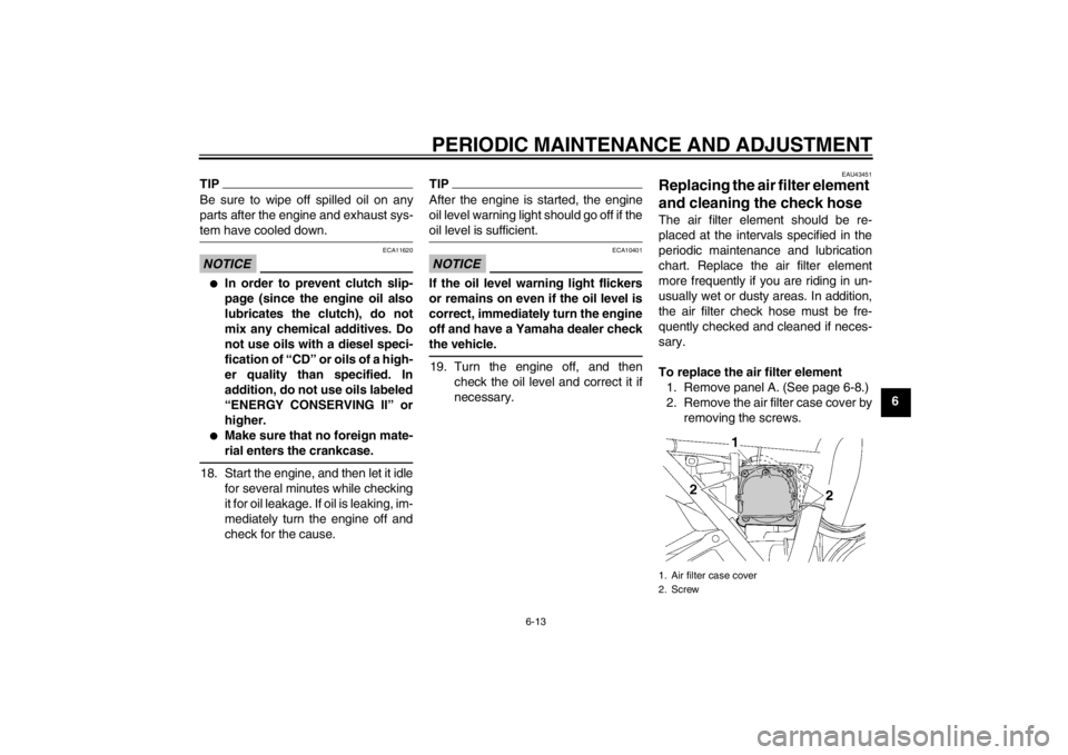
To replace the air filter element1. Remove panel A. (See page 6-8.)
2. Remove the air filter case cover by removing the screws.1. Air filter case cover
2. Screw
U5WME9E0.book Page 13 Friday, December 7, 2012 3:50 PM
Page 67 of 98
PERIODIC MAINTENANCE AND ADJUSTMENT
6-21
6
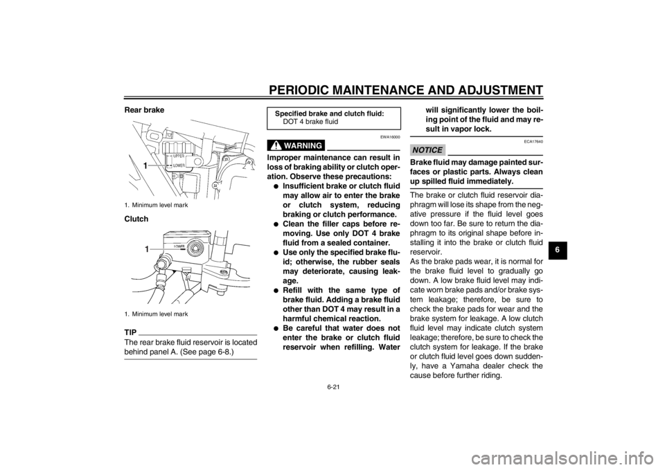
Rear brake
Clutch
TIPThe rear brake fluid reservoir is located
behind panel A. (See page 6-8.)
WARNING
EWA16000
Improper maintenance can result in
loss of braking ability or clutch oper-
ation. Observe these precautions:●
Insufficient brake or clutch fluid
may allow air to enter the brake
or clutch system, reducing
braking or clutch performance.
●
Clean the filler caps before re-
moving. Use only DOT 4 brake
fluid from a sealed container.
●
Use only the specified brake flu-
id; otherwise, the rubber seals
may deteriorate, causing leak-
age.
●
Refill with the same type of
brake fluid. Adding a brake fluid
other than DOT 4 may result in a
harmful chemical reaction.
●
Be careful that water does not
enter the brake or clutch fluid
reservoir when refilling. Water will significantly lower the boil-
ing point of the fluid and may re-
sult in vapor lock.
NOTICE
ECA17640
Brake fluid may damage painted sur-
faces or plastic parts. Always clean
up spilled fluid immediately.The brake or clutch fluid reservoir dia-
phragm will lose its shape from the neg-
ative pressure if the fluid level goes
down too far. Be sure to return the dia-
phragm to its original shape before in-
stalling it into the brake or clutch fluid
reservoir.
As the brake pads wear, it is normal for
the brake fluid level to gradually go
down. A low brake fluid level may indi-
cate worn brake pads and/or brake sys-
tem leakage; therefore, be sure to
check the brake pads for wear and the
brake system for leakage. A low clutch
fluid level may indicate clutch system
leakage; therefore, be sure to check the
clutch system for leakage. If the brake
or clutch fluid level goes down sudden-
ly, have a Yamaha dealer check the
cause before further riding.
1. Minimum level mark
1. Minimum level mark
1
Specified brake and clutch fluid:
DOT 4 brake fluid
U5WME9E0.book Page 21 Friday, December 7, 2012 3:50 PM