fuel cap YAMAHA XL 1200 2001 Owners Manual
[x] Cancel search | Manufacturer: YAMAHA, Model Year: 2001, Model line: XL 1200, Model: YAMAHA XL 1200 2001Pages: 131, PDF Size: 8.12 MB
Page 25 of 131
E
2
EJU00326
FEATURES AND
FUNCTIONS
Location of main components............... 2-1
Operation of controls and other
functions.................................................... 2-5
Rear seat................................................. 2-5
Front seat ................................................ 2-6
Hood ........................................................ 2-7
Fuel tank filler cap ................................... 2-8
Oil tank filler cap...................................... 2-8
Fuel cock knob........................................ 2-9
Engine stop switch ................................ 2-10
Engine shut-off switch........................... 2-10
Choke knob ........................................... 2-10
Throttle lever ......................................... 2-11
Start switch............................................ 2-11
Cooling water pilot outlet ...................... 2-12
Steering system .................................... 2-12
Tilt lever ................................................. 2-13
Shift lever .............................................. 2-14
Quick Shift Trim System (QSTS)
selector .................................................. 2-15
Engine overheat warning system ......... 2-17
Handgrip................................................ 2-19
Multifunction meter................................ 2-20
PADLOC (Programmable digital locking
ignition) .................................................. 2-21
Tachometer ........................................... 2-23
Speedometer ........................................ 2-24
Fuel meter ............................................. 2-24
Engine oil meter .................................... 2-25
Clock ..................................................... 2-25
Hour meter ............................................ 2-26
Trip timer ............................................... 2-26
Tripmeter ............................................... 2-27
Fuel warning indicator........................... 2-27
Oil warning indicator ............................. 2-28
Engine overheat warning indicator....... 2-28
Battery warning indicator ...................... 2-29
Storage compartments ......................... 2-30
Page 27 of 131
2-2
E
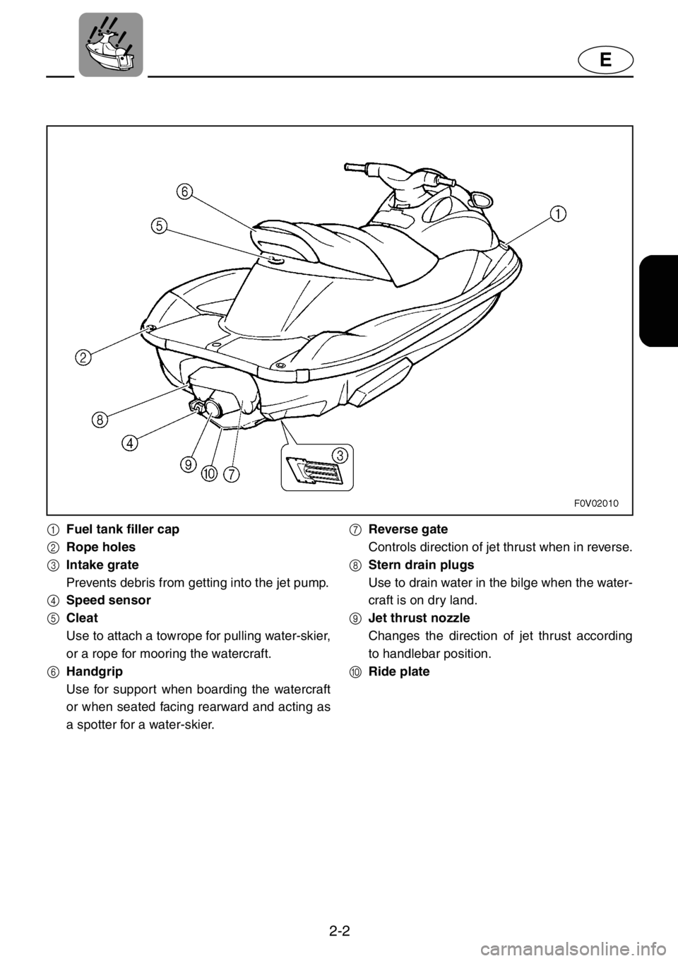
1Fuel tank filler cap
2Rope holes
3Intake grate
Prevents debris from getting into the jet pump.
4Speed sensor
5Cleat
Use to attach a towrope for pulling water-skier,
or a rope for mooring the watercraft.
6Handgrip
Use for support when boarding the watercraft
or when seated facing rearward and acting as
a spotter for a water-skier.7Reverse gate
Controls direction of jet thrust when in reverse.
8Stern drain plugs
Use to drain water in the bilge when the water-
craft is on dry land.
9Jet thrust nozzle
Changes the direction of jet thrust according
to handlebar position.
0Ride plate
Page 29 of 131
2-4
E
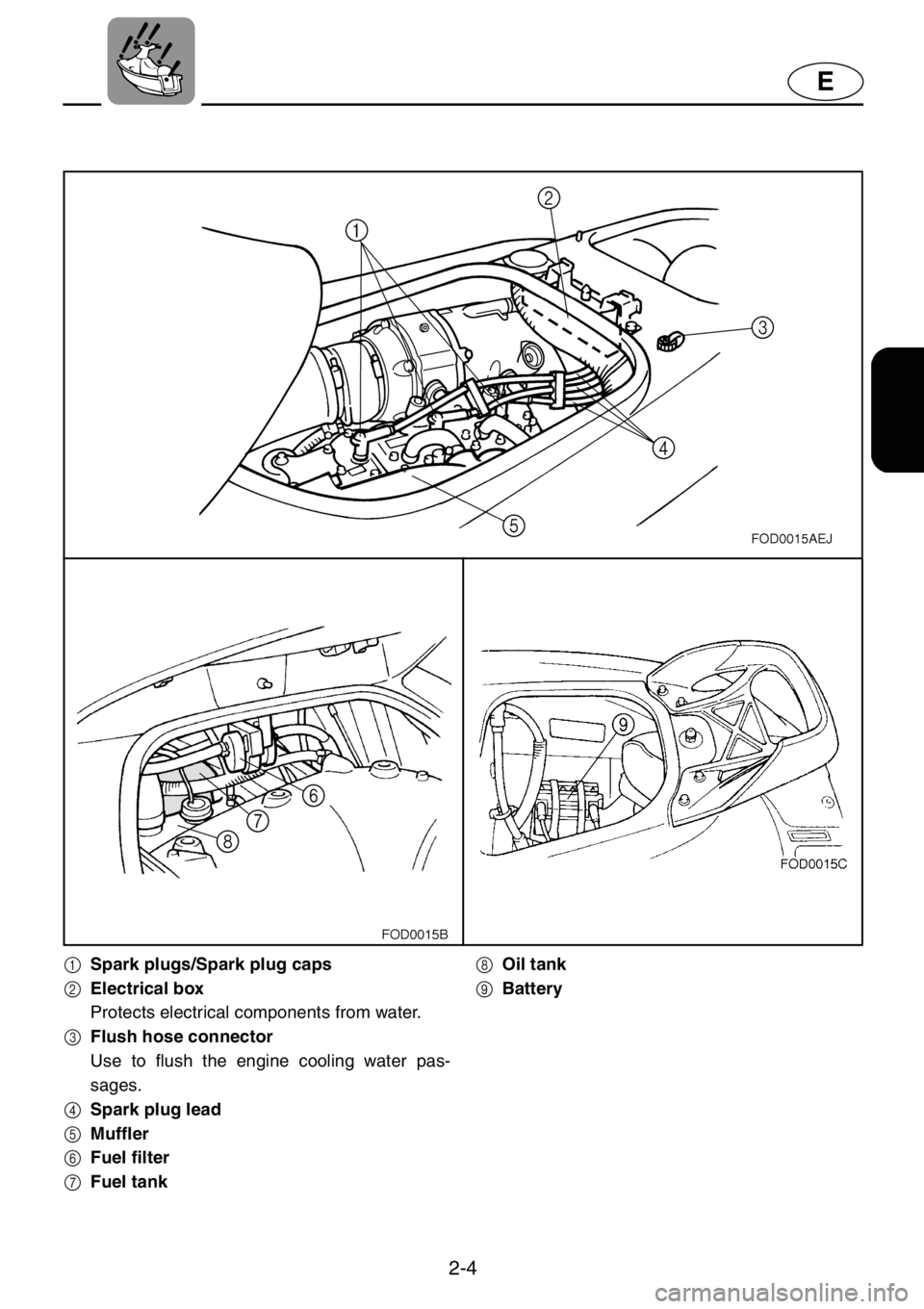
1Spark plugs/Spark plug caps
2Electrical box
Protects electrical components from water.
3Flush hose connector
Use to flush the engine cooling water pas-
sages.
4Spark plug lead
5Muffler
6Fuel filter
7Fuel tank8Oil tank
9Battery
Page 33 of 131
2-8
E
EJU00347
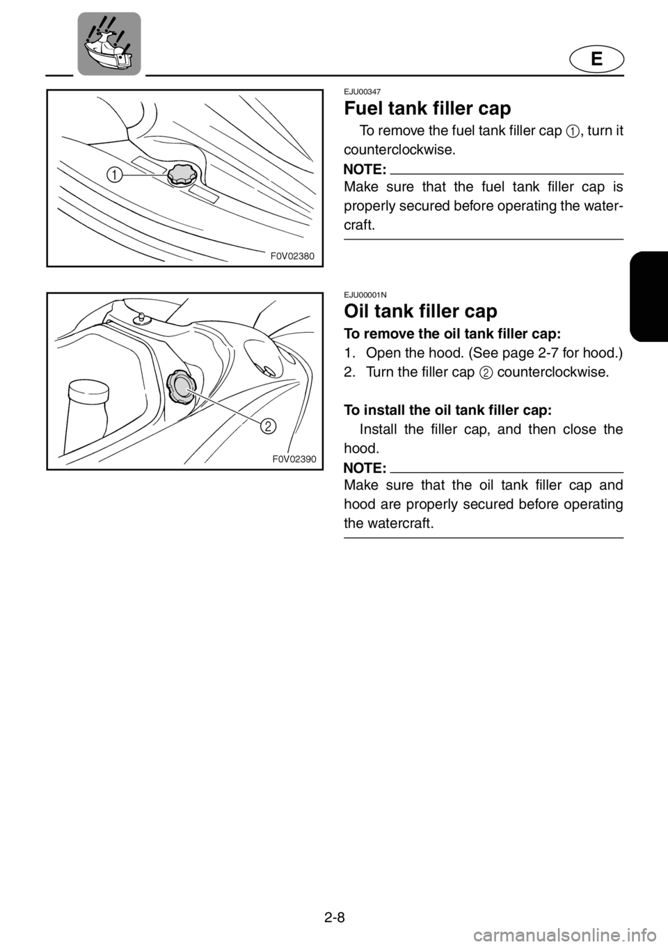
Fuel tank filler cap
To remove the fuel tank filler cap 1, turn it
counterclockwise.
NOTE:
Make sure that the fuel tank filler cap is
properly secured before operating the water-
craft.
EJU00001N
Oil tank filler cap
To remove the oil tank filler cap:
1. Open the hood. (See page 2-7 for hood.)
2. Turn the filler cap 2 counterclockwise.
To install the oil tank filler cap:
Install the filler cap, and then close the
hood.
NOTE:
Make sure that the oil tank filler cap and
hood are properly secured before operating
the watercraft.
Page 45 of 131
2-20
E
EJU00698b
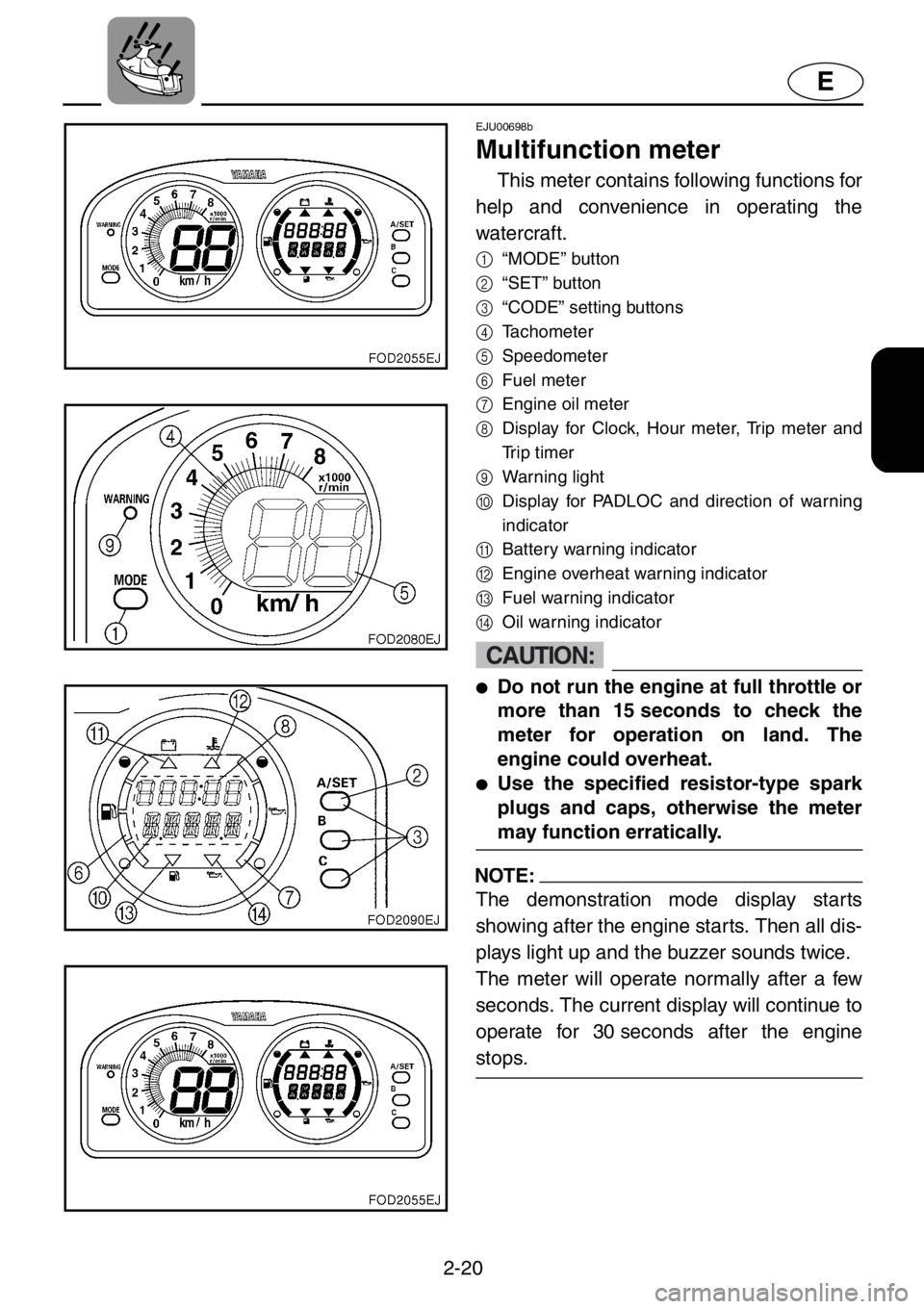
Multifunction meter
This meter contains following functions for
help and convenience in operating the
watercraft.
1
“MODE” button
2
“SET” button
3
“CODE” setting buttons
4
Tachometer
5
Speedometer
6
Fuel meter
7
Engine oil meter
8
Display for Clock, Hour meter, Trip meter and
Trip timer
9
Warning light
0
Display for PADLOC and direction of warning
indicator
A
Battery warning indicator
B
Engine overheat warning indicator
C
Fuel warning indicator
D
Oil warning indicator
CAUTION:
●Do not run the engine at full throttle or
more than 15 seconds to check the
meter for operation on land. The
engine could overheat.
●Use the specified resistor-type spark
plugs and caps, otherwise the meter
may function erratically.
NOTE:
The demonstration mode display starts
showing after the engine starts. Then all dis-
plays light up and the buzzer sounds twice.
The meter will operate normally after a few
seconds. The current display will continue to
operate for 30 seconds after the engine
stops.
Page 57 of 131
E
3
EJU00410
OPERATION
Fuel and oil................................................ 3-1
Gasoline .................................................. 3-1
Filling the fuel tank .................................. 3-3
2-stroke engine oil................................... 3-3
Filling the oil tank .................................... 3-4
Pre-operation checks............................... 3-5
Pre-operation check list .......................... 3-5
Pre-operation check points..................... 3-6
Operation................................................. 3-14
Engine break-in ..................................... 3-14
Launching the watercraft ...................... 3-16
Starting the engine................................ 3-16
Stopping the engine.............................. 3-19
Leaving the watercraft .......................... 3-19
Operating your watercraft..................... 3-20
Getting to know your watercraft............ 3-20
Learning to operate your watercraft ..... 3-20
Riding watercraft with passengers ....... 3-21
Starting the watercraft........................... 3-22
Boarding and starting in deep water .... 3-24
Capsized watercraft .............................. 3-26
Turning the watercraft........................... 3-28
Stopping the watercraft......................... 3-30
Beaching the watercraft ........................ 3-31
Docking the watercraft .......................... 3-31
Reverse on waterways ......................... 3-32
Rough water operation ......................... 3-32
Post-operation checks.......................... 3-33
Transporting........................................... 3-35
Page 58 of 131
3-1
E
EJU00411a
Fuel and oil
This engine uses Yamaha’s oil injection
system, which provides superior lubrication
by ensuring the proper oil ratio for all operat-
ing conditions. No fuel premixing is neces-
sary except during the engine break-in
period. Simply pour gasoline into the fuel
tank and oil into the oil tank.
Gasoline
WARNING
GASOLINE AND ITS VAPORS ARE
HIGHLY FLAMMABLE AND EXPLOSIVE!
●Do not smoke when refueling, and
keep away from sparks, flames, or
other sources of ignition.
●Stop engine before refueling.
●Refuel in a well-ventilated area. Do not
stand or sit on the watercraft while
refueling in case of fire.
●Take care not to spill gasoline. If gaso-
line spills, wipe it up immediately with
dry rags. Always properly dispose of
gasoline-soaked rags.
●Avoid overfilling the fuel tank. Stop fill-
ing when the fuel level just reaches the
bottom of the filler tube. Do not fill up
the filler tube because fuel expands as
it warms up and could overflow.
●Tighten the filler cap securely after
refueling.
●If you should swallow some gasoline,
inhale a lot of gasoline vapor, or get
gasoline in your eyes, get immediate
medical attention.
●If any gasoline spills onto your skin,
immediately wash with soap and
water. Change clothing if gasoline
spills on it.
Page 60 of 131
3-3
E
EJU00724a
Filling the fuel tank
CAUTION:
Be careful when refueling. Avoid getting
water or other contaminants in the fuel
tank. Contaminated fuel can cause poor
running or engine damage.
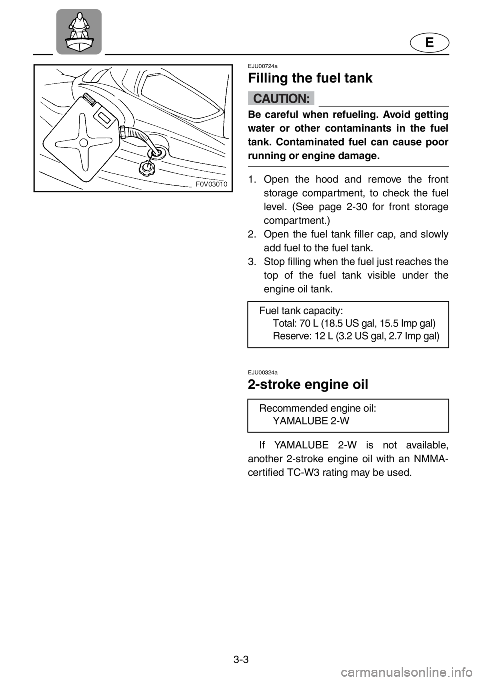
1. Open the hood and remove the front
storage compartment, to check the fuel
level. (See page 2-30 for front storage
compartment.)
2. Open the fuel tank filler cap, and slowly
add fuel to the fuel tank.
3. Stop filling when the fuel just reaches the
top of the fuel tank visible under the
engine oil tank.
EJU00324a
2-stroke engine oil
If YAMALUBE 2-W is not available,
another 2-stroke engine oil with an NMMA-
certified TC-W3 rating may be used.Fuel tank capacity:
Total: 70 L (18.5 US gal, 15.5 Imp gal)
Reserve: 12 L (3.2 US gal, 2.7 Imp gal)
Recommended engine oil:
YAMALUBE 2-W
Page 63 of 131
3-6
E
EJU00426
Pre-operation check points
Engine compartment
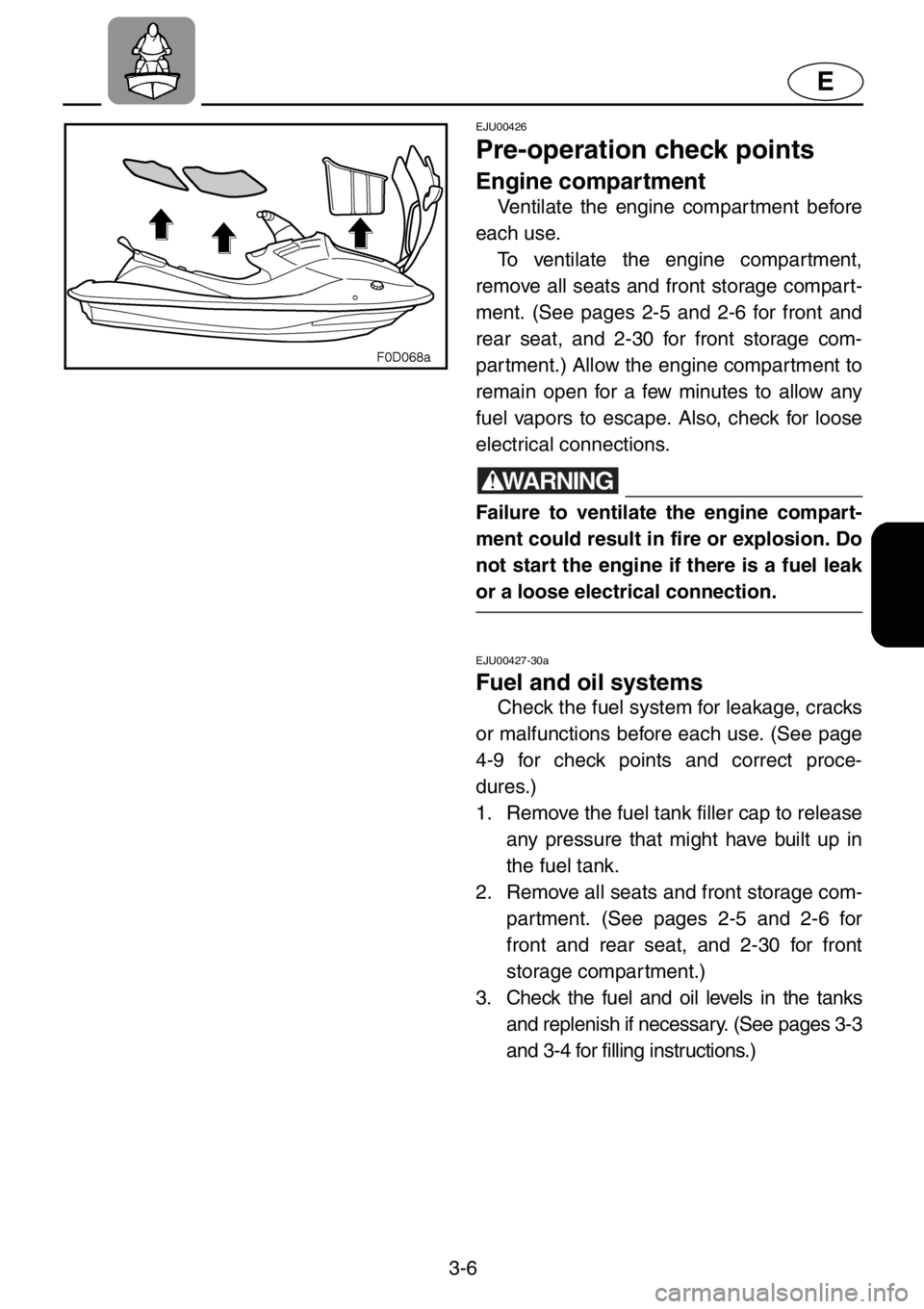
Ventilate the engine compar tment before
each use.
To ventilate the engine compartment,
remove all seats and front storage compart-
ment. (See pages 2-5 and 2-6 for front and
rear seat, and 2-30 for front storage com-
partment.) Allow the engine compartment to
remain open for a few minutes to allow any
fuel vapors to escape. Also, check for loose
electrical connections.
WARNING
Failure to ventilate the engine compart-
ment could result in fire or explosion. Do
not start the engine if there is a fuel leak
or a loose electrical connection.
EJU00427-30a
Fuel and oil systems
Check the fuel system for leakage, cracks
or malfunctions before each use. (See page
4-9 for check points and correct proce-
dures.)
1. Remove the fuel tank filler cap to release
any pressure that might have built up in
the fuel tank.
2. Remove all seats and front storage com-
partment. (See pages 2-5 and 2-6 for
front and rear seat, and 2-30 for front
storage compartment.)
3. Check the fuel and oil levels in the tanks
and replenish if necessary. (See pages 3-3
and 3-4 for filling instructions.)
Page 64 of 131
3-7
E
EJU00432a
Water separator
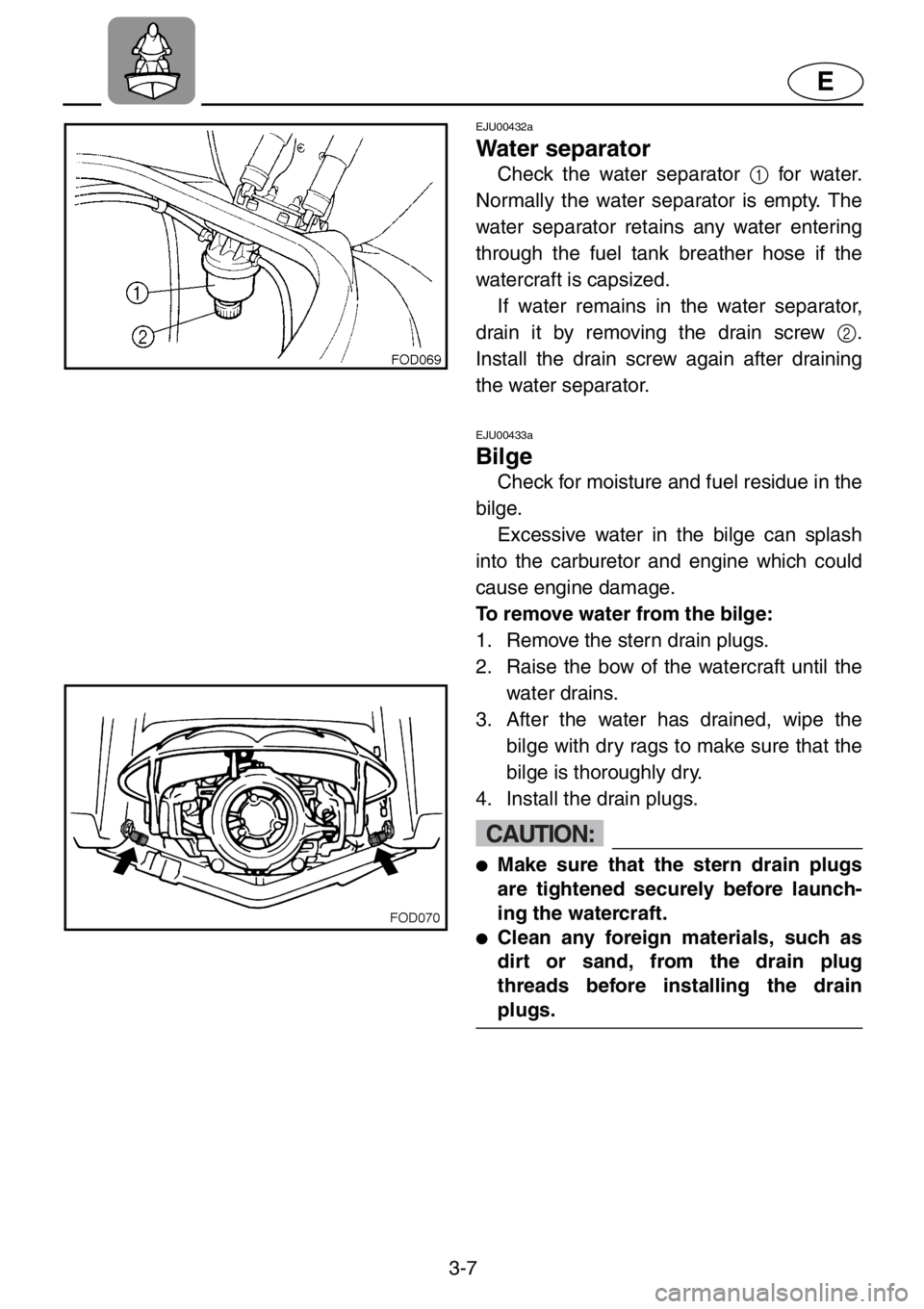
Check the water separator 1 for water.
Normally the water separator is empty. The
water separator retains any water entering
through the fuel tank breather hose if the
watercraft is capsized.
If water remains in the water separator,
drain it by removing the drain screw 2.
Install the drain screw again after draining
the water separator.
EJU00433a
Bilge
Check for moisture and fuel residue in the
bilge.
Excessive water in the bilge can splash
into the carburetor and engine which could
cause engine damage.
To remove water from the bilge:
1. Remove the stern drain plugs.
2. Raise the bow of the watercraft until the
water drains.
3. After the water has drained, wipe the
bilge with dry rags to make sure that the
bilge is thoroughly dry.
4. Install the drain plugs.
CAUTION:
●Make sure that the stern drain plugs
are tightened securely before launch-
ing the watercraft.
●Clean any foreign materials, such as
dirt or sand, from the drain plug
threads before installing the drain
plugs.