lock YAMAHA XL 1200 2001 Owners Manual
[x] Cancel search | Manufacturer: YAMAHA, Model Year: 2001, Model line: XL 1200, Model: YAMAHA XL 1200 2001Pages: 131, PDF Size: 8.12 MB
Page 16 of 131
1-9
E
EJU00613
Cruising limitations
●Scan constantly for people, objects, and
other watercraft. Be alert for conditions
that limit your visibility or block your vision
of others.
●Operate defensively at safe speeds and
keep a safe distance away from people,
objects, and other watercraft.
●Do not follow directly behind watercraft or
other boats.
●Do not go near others to spray or splash
them with water.
●Avoid sharp turns or other maneuvers
that make it hard for others to avoid you or
understand where you are going.
●Avoid areas with submerged objects or
shallow water.
●Ride within your limits and avoid aggres-
sive maneuvers to reduce the risk of loss
of control, ejection, and collision.
●This is a high performance boat—not a
toy. Sharp turns or jumping wakes or
waves can increase the risk of back/spinal
injury (paralysis), facial injuries, and bro-
ken legs, ankles and other bones. Do not
jump wakes or waves.
●Do not operate the watercraft in rough
water, bad weather or when visibility is
poor; this may lead to an accident caus-
ing injury or death. Be alert to the possi-
bility of adverse weather. Take note of
weather forecasts and the prevailing
weather conditions before setting out on
your watercraft.
●As with any water sport, you should not
ride your watercraft without someone else
near by. If you ride further than swimming
distance from shore, you should ride by
another boat or watercraft, but make sure
you stay a safe distance away. It’s good
common sense!
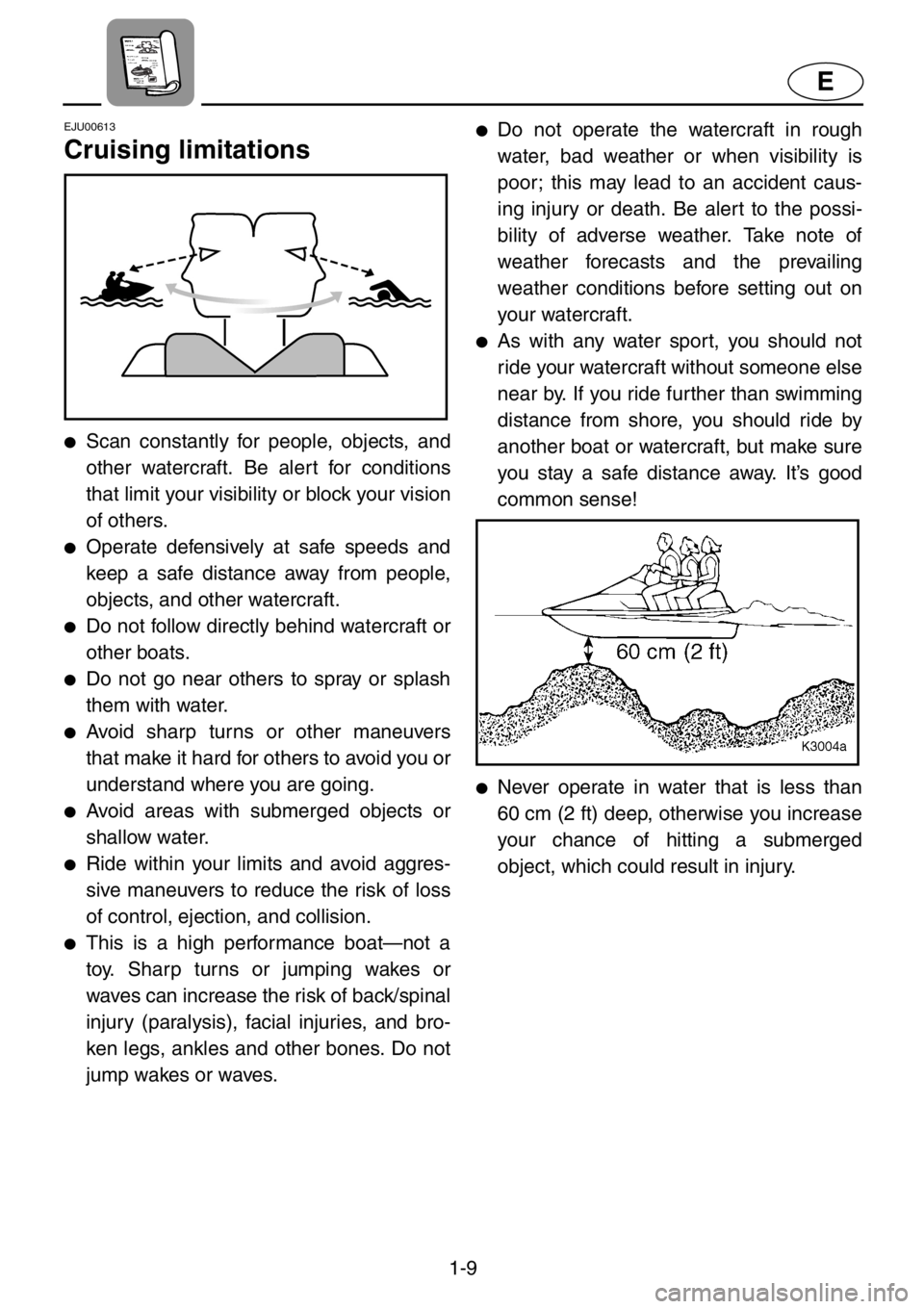
●Never operate in water that is less than
60 cm (2 ft) deep, otherwise you increase
your chance of hitting a submerged
object, which could result in injury.
Page 25 of 131
E
2
EJU00326
FEATURES AND
FUNCTIONS
Location of main components............... 2-1
Operation of controls and other
functions.................................................... 2-5
Rear seat................................................. 2-5
Front seat ................................................ 2-6
Hood ........................................................ 2-7
Fuel tank filler cap ................................... 2-8
Oil tank filler cap...................................... 2-8
Fuel cock knob........................................ 2-9
Engine stop switch ................................ 2-10
Engine shut-off switch........................... 2-10
Choke knob ........................................... 2-10
Throttle lever ......................................... 2-11
Start switch............................................ 2-11
Cooling water pilot outlet ...................... 2-12
Steering system .................................... 2-12
Tilt lever ................................................. 2-13
Shift lever .............................................. 2-14
Quick Shift Trim System (QSTS)
selector .................................................. 2-15
Engine overheat warning system ......... 2-17
Handgrip................................................ 2-19
Multifunction meter................................ 2-20
PADLOC (Programmable digital locking
ignition) .................................................. 2-21
Tachometer ........................................... 2-23
Speedometer ........................................ 2-24
Fuel meter ............................................. 2-24
Engine oil meter .................................... 2-25
Clock ..................................................... 2-25
Hour meter ............................................ 2-26
Trip timer ............................................... 2-26
Tripmeter ............................................... 2-27
Fuel warning indicator........................... 2-27
Oil warning indicator ............................. 2-28
Engine overheat warning indicator....... 2-28
Battery warning indicator ...................... 2-29
Storage compartments ......................... 2-30
Page 28 of 131
2-3
E
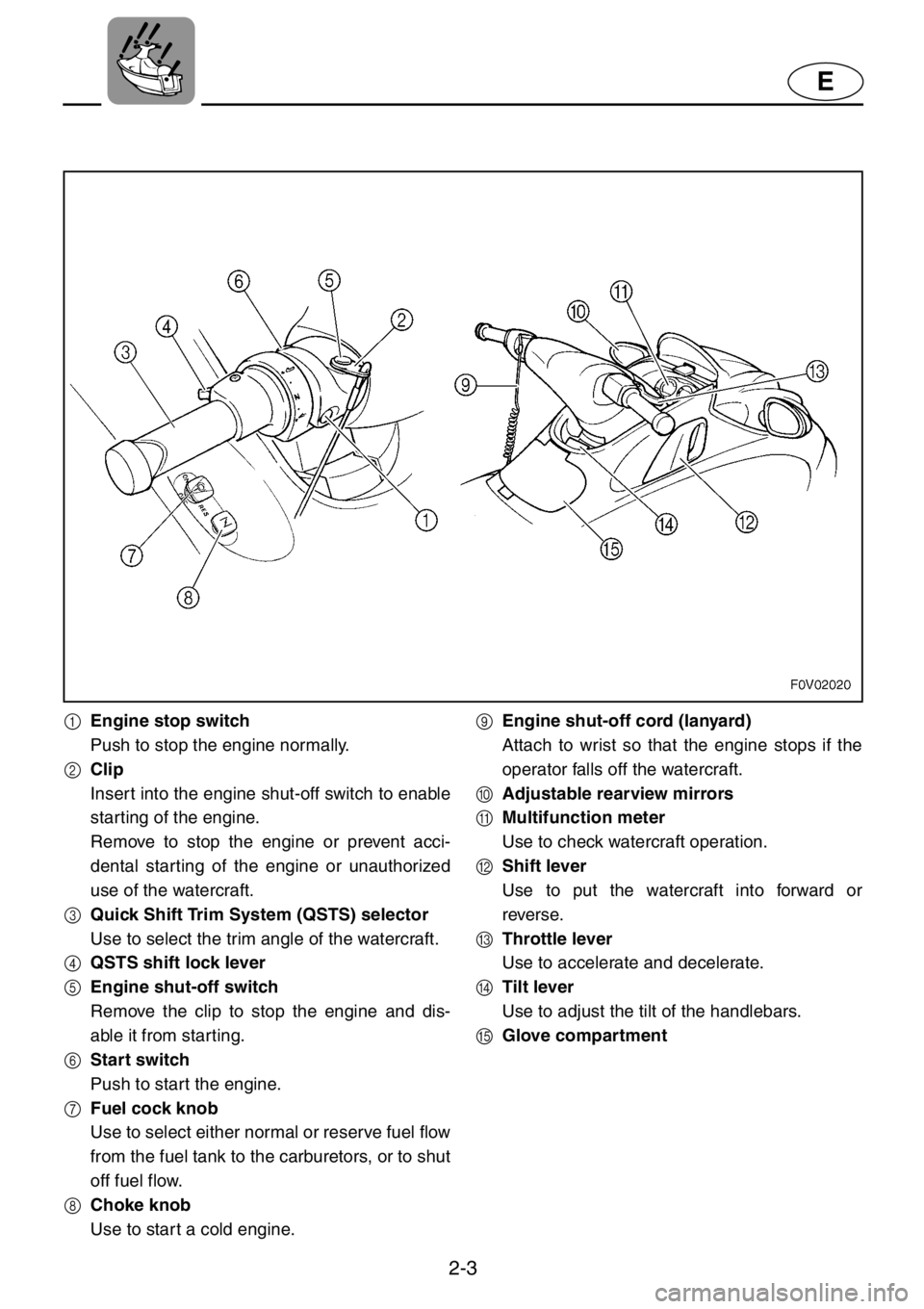
1Engine stop switch
Push to stop the engine normally.
2Clip
Insert into the engine shut-off switch to enable
starting of the engine.
Remove to stop the engine or prevent acci-
dental star ting of the engine or unauthorized
use of the watercraft.
3Quick Shift Trim System (QSTS) selector
Use to select the trim angle of the watercraft.
4QSTS shift lock lever
5Engine shut-off switch
Remove the clip to stop the engine and dis-
able it from starting.
6Start switch
Push to start the engine.
7Fuel cock knob
Use to select either normal or reserve fuel flow
from the fuel tank to the carburetors, or to shut
off fuel flow.
8Choke knob
Use to start a cold engine.9Engine shut-off cord (lanyard)
Attach to wrist so that the engine stops if the
operator falls off the watercraft.
0Adjustable rearview mirrors
AMultifunction meter
Use to check watercraft operation.
BShift lever
Use to put the watercraft into forward or
reverse.
CThrottle lever
Use to accelerate and decelerate.
DTilt lever
Use to adjust the tilt of the handlebars.
EGlove compartment
Page 30 of 131
2-5
E
EJU00328
Operation of controls and
other functions
EJU00335a
Rear seat
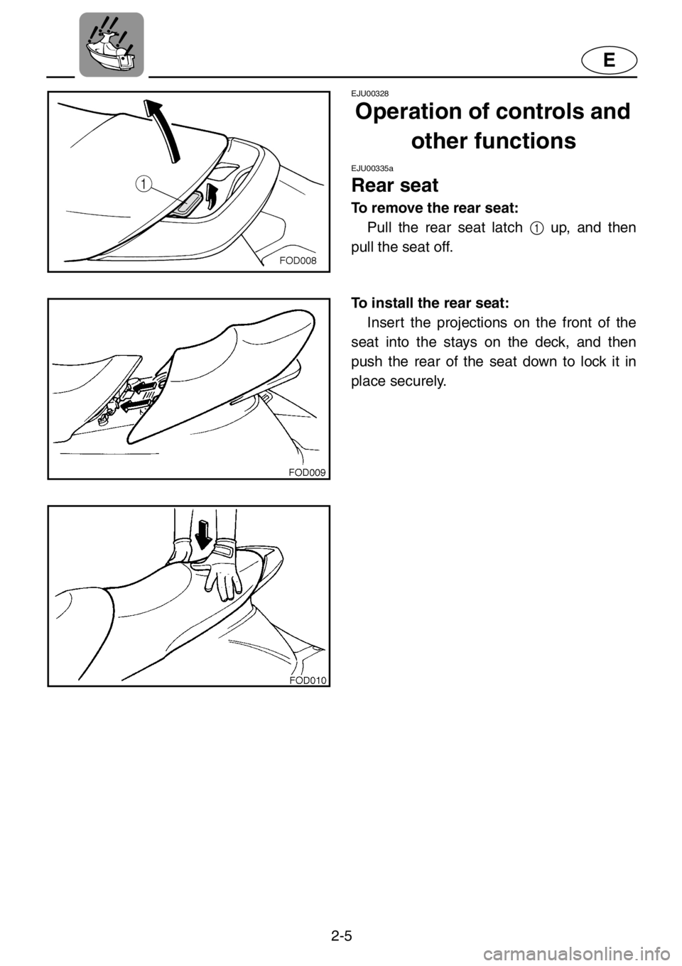
To remove the rear seat:
Pull the rear seat latch 1 up, and then
pull the seat off.
To install the rear seat:
Insert the projections on the front of the
seat into the stays on the deck, and then
push the rear of the seat down to lock it in
place securely.
Page 31 of 131
2-6
E
EJU00714
Front seat
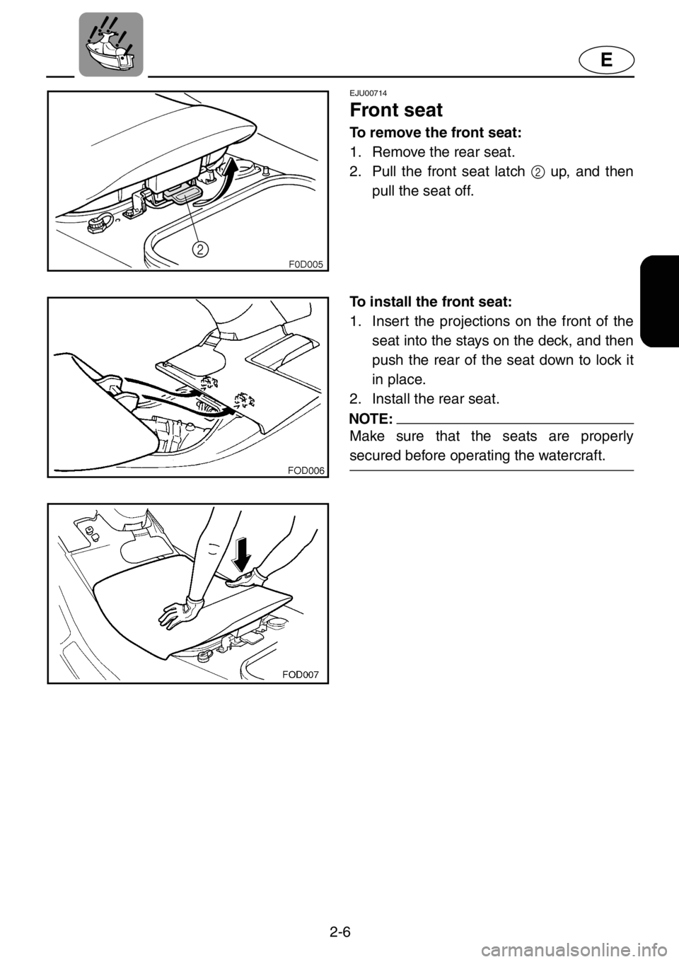
To remove the front seat:
1. Remove the rear seat.
2. Pull the front seat latch 2 up, and then
pull the seat off.
To install the front seat:
1. Insert the projections on the front of the
seat into the stays on the deck, and then
push the rear of the seat down to lock it
in place.
2. Install the rear seat.
NOTE:
Make sure that the seats are properly
secured before operating the watercraft.
Page 32 of 131
2-7
E
EJU00703
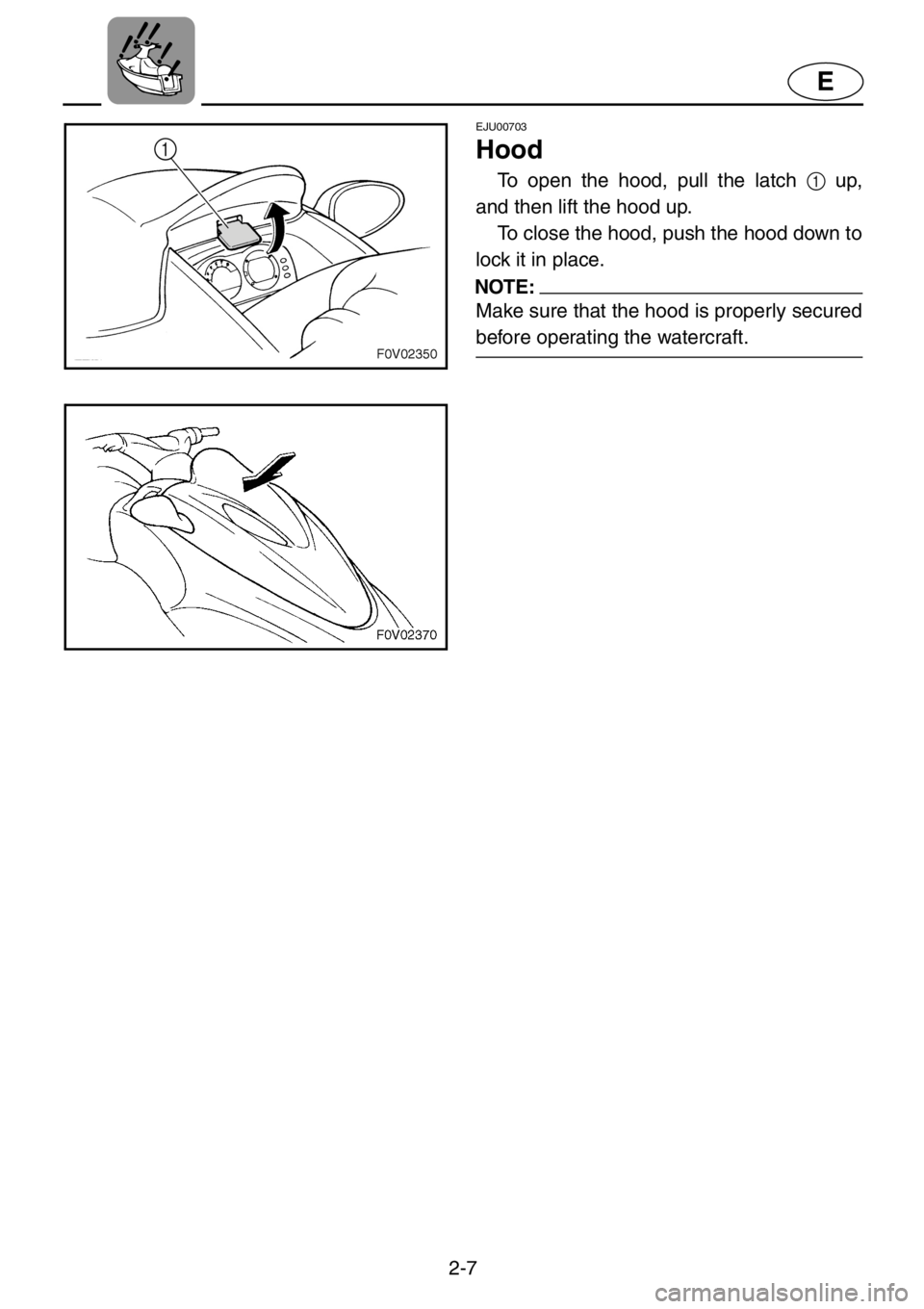
Hood
To open the hood, pull the latch 1 up,
and then lift the hood up.
To close the hood, push the hood down to
lock it in place.
NOTE:
Make sure that the hood is properly secured
before operating the watercraft.
Page 33 of 131
2-8
E
EJU00347
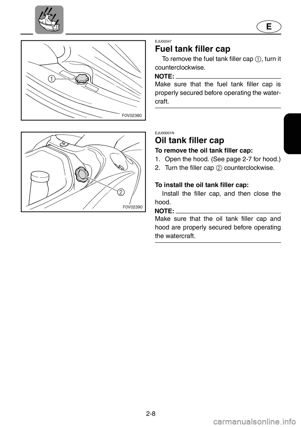
Fuel tank filler cap
To remove the fuel tank filler cap 1, turn it
counterclockwise.
NOTE:
Make sure that the fuel tank filler cap is
properly secured before operating the water-
craft.
EJU00001N
Oil tank filler cap
To remove the oil tank filler cap:
1. Open the hood. (See page 2-7 for hood.)
2. Turn the filler cap 2 counterclockwise.
To install the oil tank filler cap:
Install the filler cap, and then close the
hood.
NOTE:
Make sure that the oil tank filler cap and
hood are properly secured before operating
the watercraft.
Page 36 of 131
2-11
E
EJU00351
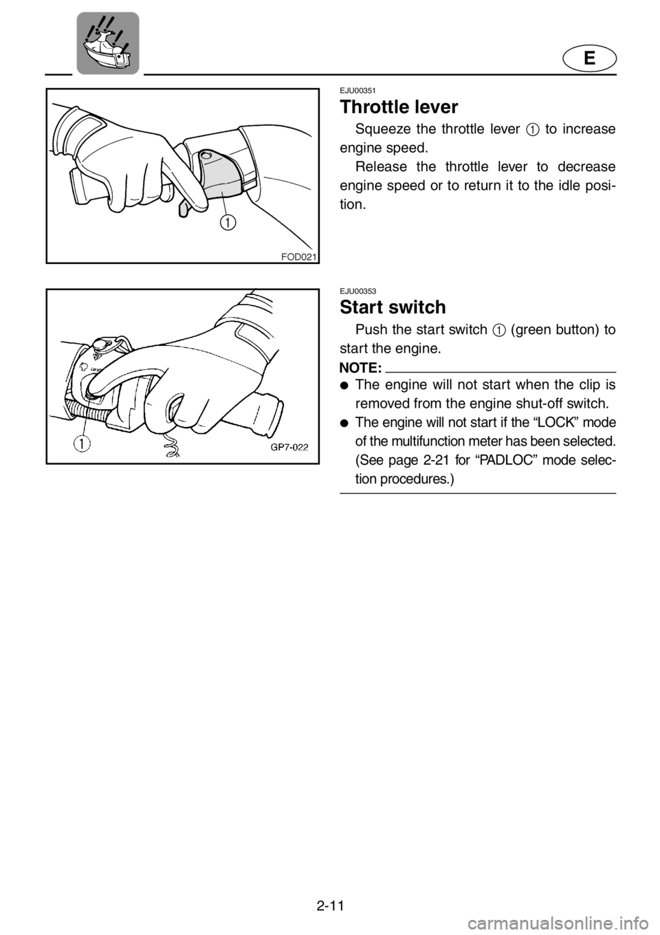
Throttle lever
Squeeze the throttle lever 1 to increase
engine speed.
Release the throttle lever to decrease
engine speed or to return it to the idle posi-
tion.
EJU00353
Start switch
Push the start switch 1 (green button) to
start the engine.
NOTE:
●The engine will not start when the clip is
removed from the engine shut-off switch.
●The engine will not start if the “LOCK” mode
of the multifunction meter has been selected.
(See page 2-21 for “PADLOC” mode selec-
tion procedures.)
Page 40 of 131
2-15
E
EJU00360a
Quick Shift Trim System
(QSTS) selector
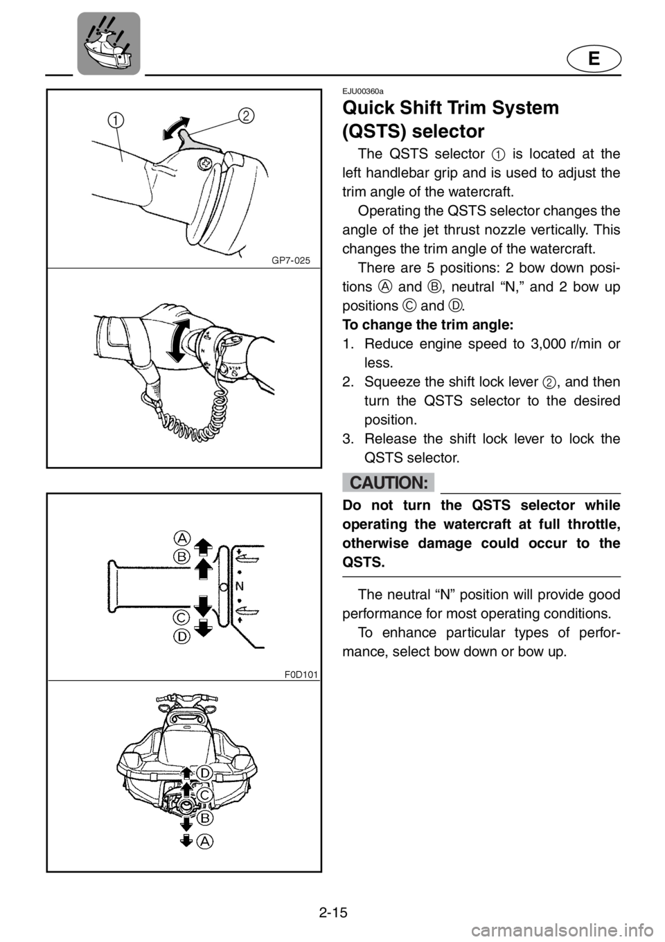
The QSTS selector 1 is located at the
left handlebar grip and is used to adjust the
trim angle of the watercraft.
Operating the QSTS selector changes the
angle of the jet thrust nozzle vertically. This
changes the trim angle of the watercraft.
There are 5 positions: 2 bow down posi-
tionsA and B, neutral “N,” and 2 bow up
positionsC and D.
To change the trim angle:
1. Reduce engine speed to 3,000 r/min or
less.
2. Squeeze the shift lock lever 2, and then
turn the QSTS selector to the desired
position.
3. Release the shift lock lever to lock the
QSTS selector.
CAUTION:
Do not turn the QSTS selector while
operating the watercraft at full throttle,
otherwise damage could occur to the
QSTS.
The neutral “N” position will provide good
performance for most operating conditions.
To enhance particular types of perfor-
mance, select bow down or bow up.
Page 45 of 131
2-20
E
EJU00698b
Multifunction meter
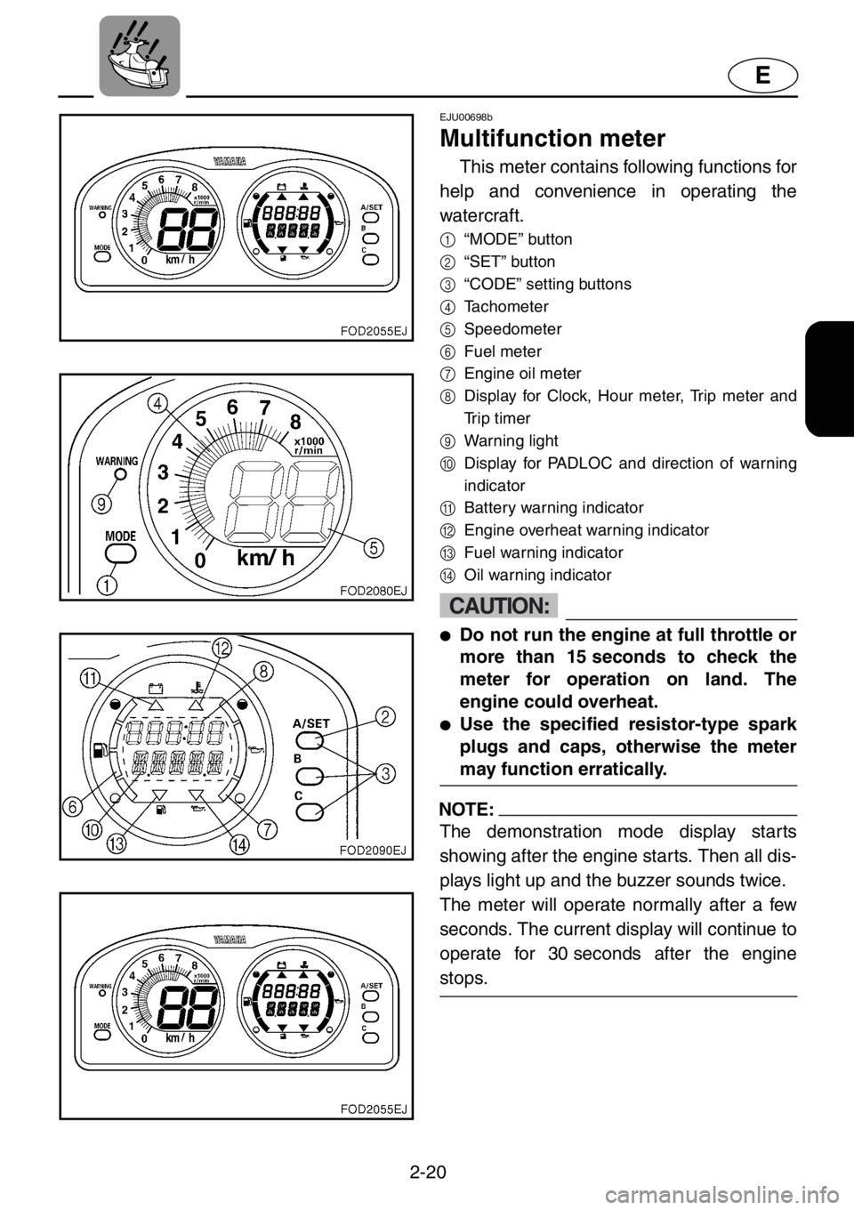
This meter contains following functions for
help and convenience in operating the
watercraft.
1
“MODE” button
2
“SET” button
3
“CODE” setting buttons
4
Tachometer
5
Speedometer
6
Fuel meter
7
Engine oil meter
8
Display for Clock, Hour meter, Trip meter and
Trip timer
9
Warning light
0
Display for PADLOC and direction of warning
indicator
A
Battery warning indicator
B
Engine overheat warning indicator
C
Fuel warning indicator
D
Oil warning indicator
CAUTION:
●Do not run the engine at full throttle or
more than 15 seconds to check the
meter for operation on land. The
engine could overheat.
●Use the specified resistor-type spark
plugs and caps, otherwise the meter
may function erratically.
NOTE:
The demonstration mode display starts
showing after the engine starts. Then all dis-
plays light up and the buzzer sounds twice.
The meter will operate normally after a few
seconds. The current display will continue to
operate for 30 seconds after the engine
stops.