oil filter YAMAHA XMAX 125 2014 Owners Manual
[x] Cancel search | Manufacturer: YAMAHA, Model Year: 2014, Model line: XMAX 125, Model: YAMAHA XMAX 125 2014Pages: 94, PDF Size: 8.21 MB
Page 6 of 94

TABLE OF CONTENTSSAFETY INFORMATION.................. 1-1
Further safe-riding points ............... 1-5
DESCRIPTION.................................. 2-1
Left view ......................................... 2-1
Right view ....................................... 2-2
Controls and instruments ............... 2-3
INSTRUMENT AND CONTROL
FUNCTIONS...................................... 3-1
Immobilizer system......................... 3-1
Main switch/steering lock............... 3-2
Indicator lights and warning
lights............................................ 3-3
Multi-function meter unit ................ 3-5
Anti-theft alarm (optional) ............. 3-13
Handlebar switches ...................... 3-14
Front brake lever .......................... 3-15
Rear brake lever ........................... 3-15
ABS (for ABS models) .................. 3-16
Fuel tank cap ................................ 3-17
Fuel ............................................... 3-17
Catalytic converters...................... 3-19
Seat .............................................. 3-19
Storage compartments................. 3-20
Adjusting the shock absorber
assemblies ................................ 3-21
Sidestand ..................................... 3-22
Ignition circuit cut-off system ....... 3-23FOR YOUR SAFETY –
PRE-OPERATION CHECKS............. 4-1
OPERATION AND IMPORTANT
RIDING POINTS................................ 5-1
Starting the engine .......................... 5-1
Starting off ...................................... 5-2
Acceleration and deceleration ........ 5-3
Braking ............................................ 5-3
Tips for reducing fuel
consumption ................................ 5-4
Engine break-in ............................... 5-4
Parking ............................................ 5-5
PERIODIC MAINTENANCE AND
ADJUSTMENT................................... 6-1
Owner’s tool kit ............................... 6-2
Periodic maintenance chart for the
emission control system .............. 6-3
General maintenance and
lubrication chart ........................... 6-4
Removing and installing panels ...... 6-8
Checking the spark plug ............... 6-10
Engine oil....................................... 6-12
Final transmission oil..................... 6-14
Coolant.......................................... 6-15
Air filter and V-belt case air filter
elements and check hoses ........ 6-16
Checking the throttle grip free
play ............................................ 6-18
Valve clearance ............................. 6-18Tires .............................................. 6-18
Cast wheels .................................. 6-20
Checking the front and rear brake
lever free play ............................ 6-21
Checking the front and rear brake
pads .......................................... 6-21
Checking the brake fluid level ...... 6-22
Changing the brake fluid .............. 6-24
Checking and lubricating the
cables ........................................ 6-24
Checking and lubricating the
throttle grip and cable ............... 6-24
Lubricating the front and rear
brake levers ............................... 6-25
Checking and lubricating the
centerstand and sidestand........ 6-25
Checking the front fork ................. 6-26
Checking the steering................... 6-27
Checking the wheel bearings ....... 6-27
Battery .......................................... 6-27
Replacing the fuses ...................... 6-29
Replacing a headlight bulb ........... 6-30
Tail/brake light .............................. 6-31
Front turn signal light .................... 6-31
Replacing a rear turn signal light
bulb ........................................... 6-31
Replacing the license plate light
bulb ........................................... 6-32
Auxiliary light ................................ 6-33
Troubleshooting............................ 6-33
Troubleshooting charts................. 6-34U2DME1E0.book Page 1 Wednesday, October 23, 2013 1:37 PM
Page 14 of 94
DESCRIPTION
2-1
2
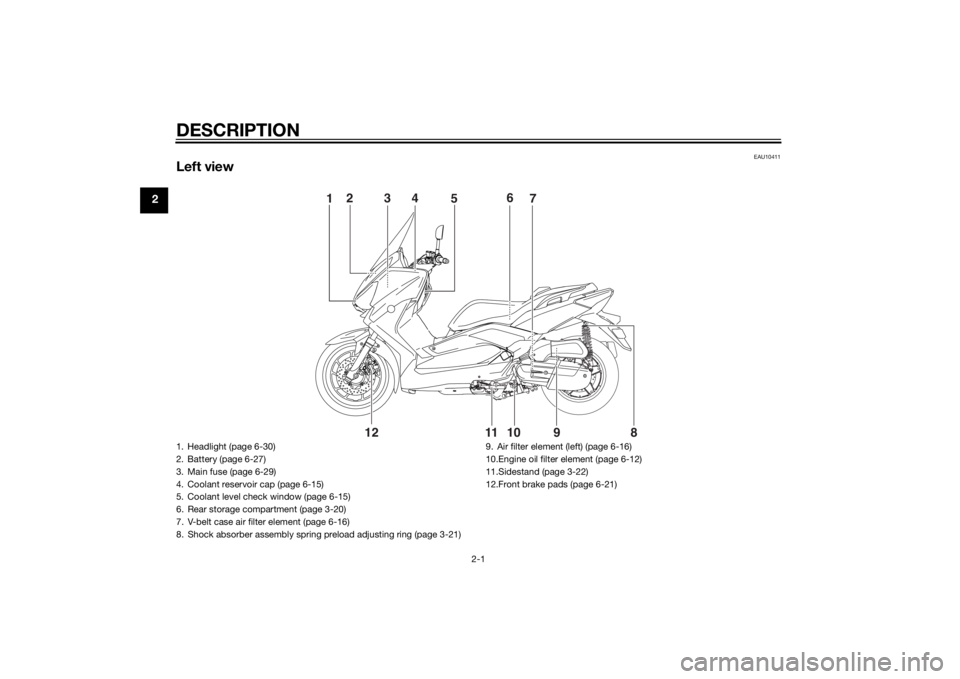
EAU10411
Left view
1
5
2
4
3
7 6
98 10 11
12
1. Headlight (page 6-30)
2. Battery (page 6-27)
3. Main fuse (page 6-29)
4. Coolant reservoir cap (page 6-15)
5. Coolant level check window (page 6-15)
6. Rear storage compartment (page 3-20)
7. V-belt case air filter element (page 6-16)
8. Shock absorber assembly spring preload adjusting ring (page 3-21)9. Air filter element (left) (page 6-16)
10.Engine oil filter element (page 6-12)
11.Sidestand (page 3-22)
12.Front brake pads (page 6-21)U2DME1E0.book Page 1 Wednesday, October 23, 2013 1:37 PM
Page 46 of 94
OPERATION AND IMPORTANT RIDING POINTS
5-4
5
EAU16821
Tips for reducing fuel con-
sumptionFuel consumption depends largely on
your riding style. Consider the follow-
ing tips to reduce fuel consumption:
Avoid high engine speeds during
acceleration.
Avoid high engine speeds with no
load on the engine.
Turn the engine off instead of let-
ting it idle for an extended length
of time (e.g., in traffic jams, at traf-
fic lights or at railroad crossings).
EAU16831
Engine break-inThere is never a more important period
in the life of your engine than the period
between 0 and 1000 km (600 mi). For
this reason, you should read the fol-
lowing material carefully.
Since the engine is brand new, do not
put an excessive load on it for the first
1000 km (600 mi). The various parts in
the engine wear and polish themselves
to the correct operating clearances.
During this period, prolonged full-throt-
tle operation or any condition that
might result in engine overheating
must be avoided.
EAUS1841
0–500 km (0–300 mi)
Avoid prolonged operation above 5000
r/min.
500–1000 km (300–600 mi)
Avoid prolonged operation above 7500
r/min. NOTICE: After 1000 km (600
mi) of operation, be sure to replace
the engine oil, final transmission oil
and the oil filter element.
[ECA12932]
1000 km (600 mi) and beyond
The vehicle can now be operated nor-
mally.NOTICE
ECA10311
Keep the engine speed out of
the tachometer red zone.
If any engine trouble should oc-
cur during the engine break-in
period, immediately have a
Yamaha dealer check the vehi-
cle.
U2DME1E0.book Page 4 Wednesday, October 23, 2013 1:37 PM
Page 52 of 94

PERIODIC MAINTENANCE AND ADJUSTMENT
6-5
6
11*Steering bearings• Check bearing play and steering
for roughness.√√√√√
• Lubricate with lithium-soap-
based grease.Every 24000 km (14000 mi)
12*Chassis fasteners• Make sure that all nuts, bolts and
screws are properly tightened.√√√√√
13Front brake lever
pivot shaft• Lubricate with silicone grease.√√√√√
14Rear brake lever
pivot shaft• Lubricate with silicone grease.√√√√√
15Sidestand, center-
stand• Check operation.
• Lubricate with lithium-soap-
based grease.√√√√√
16*Sidestand switch• Check operation.√√√√√√
17*Front fork• Check operation and for oil leak-
age.√√√√
18*Shock absorber as-
semblies• Check operation and shock ab-
sorbers for oil leakage.√√√√
19 Engine oil• Change. (See pages 3-8 and
6-12.)√When the oil change indicator light flashes (5000 km (3000 mi) af-
ter the initial 1000 km [600 mi] and every 6000 km (3500 mi)
thereafter)
• Check oil level and vehicle for oil
leakage.Every 3000 km (1800 mi)√
20Engine oil filter ele-
ment• Replace.√√√ NO. ITEM CHECK OR MAINTENANCE JOBODOMETER READING
ANNUAL
CHECK 1000 km
(600 mi)6000 km
(3500 mi)12000 km
(7000 mi)18000 km
(10500 mi)24000 km
(14000 mi)
U2DME1E0.book Page 5 Wednesday, October 23, 2013 1:37 PM
Page 53 of 94
PERIODIC MAINTENANCE AND ADJUSTMENT
6-6
6
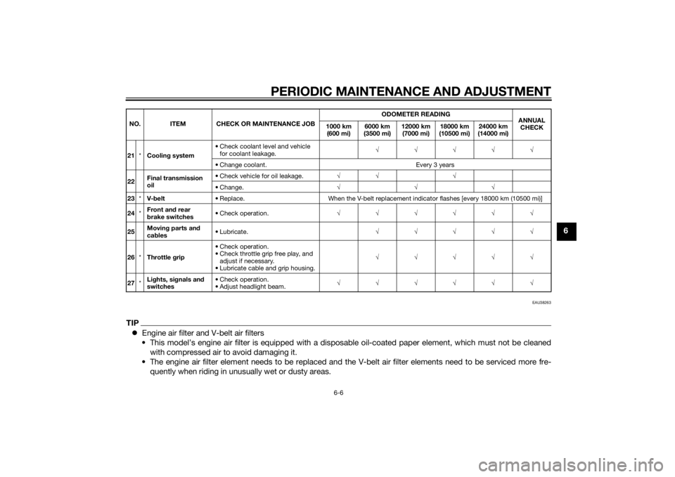
EAU38263
TIPEngine air filter and V-belt air filters
• This model’s engine air filter is equipped with a disposable oil-coated paper element, which must not be cleaned
with compressed air to avoid damaging it.
• The engine air filter element needs to be replaced and the V-belt air filter elements need to be serviced more fre-
quently when riding in unusually wet or dusty areas.21*Cooling system• Check coolant level and vehicle
for coolant leakage.√√√√√
• Change coolant. Every 3 years
22Final transmission
oil• Check vehicle for oil leakage.√√ √
• Change.√√√
23*V-belt• Replace. When the V-belt replacement indicator flashes [every 18000 km (10500 mi)]
24*Front and rear
brake switches• Check operation.√√√√√√
25Moving parts and
cables• Lubricate.√√√√√
26*Throttle grip• Check operation.
• Check throttle grip free play, and
adjust if necessary.
• Lubricate cable and grip housing.√√√√√
27*Lights, signals and
switches• Check operation.
• Adjust headlight beam.√√√√√√ NO. ITEM CHECK OR MAINTENANCE JOBODOMETER READING
ANNUAL
CHECK 1000 km
(600 mi)6000 km
(3500 mi)12000 km
(7000 mi)18000 km
(10500 mi)24000 km
(14000 mi)
U2DME1E0.book Page 6 Wednesday, October 23, 2013 1:37 PM
Page 59 of 94
PERIODIC MAINTENANCE AND ADJUSTMENT
6-12
6
EAUM3331
Engine oilThe engine oil level should be checked
before each ride. In addition, the oil
must be changed at the intervals spec-
ified in the periodic maintenance and
lubrication chart and when the service
indicator light comes on.
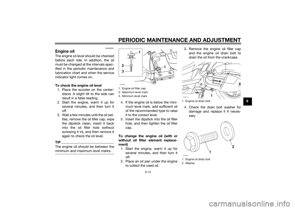
To check the engine oil level
1. Place the scooter on the center-
stand. A slight tilt to the side can
result in a false reading.
2. Start the engine, warm it up for
several minutes, and then turn it
off.
3. Wait a few minutes until the oil set-
tles, remove the oil filler cap, wipe
the dipstick clean, insert it back
into the oil filler hole (without
screwing it in), and then remove it
again to check the oil level.TIPThe engine oil should be between the
minimum and maximum level marks.
4. If the engine oil is below the mini-
mum level mark, add sufficient oil
of the recommended type to raise
it to the correct level.
5. Insert the dipstick into the oil filler
hole, and then tighten the oil filler
cap.
To change the engine oil (with or
without oil filter element replace-
ment)
1. Start the engine, warm it up for
several minutes, and then turn it
off.
2. Place an oil pan under the engine
to collect the used oil.3. Remove the engine oil filler cap
and the engine oil drain bolt to
drain the oil from the crankcase.
4. Check the drain bolt washer for
damage and replace it if neces-
sary.1. Engine oil filler cap
2. Maximum level mark
3. Minimum level mark
1
32
1
ZAUM0685
1. Engine oil drain bolt
1. Engine oil drain bolt
2. WasherZAUM1119
11
2
ZAUM0129
U2DME1E0.book Page 12 Wednesday, October 23, 2013 1:37 PM
Page 60 of 94
PERIODIC MAINTENANCE AND ADJUSTMENT
6-13
6
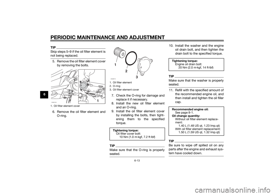
TIPSkip steps 5–9 if the oil filter element is
not being replaced.5. Remove the oil filter element cover
by removing the bolts.
6. Remove the oil filter element and
O-ring.7. Check the O-ring for damage and
replace it if necessary.
8. Install the new oil filter element
and an O-ring.
9. Install the oil filter element cover
by installing the bolts, then tight-
ening them to the specified
torque.
TIPMake sure that the O-ring is properly
seated.
10. Install the washer and the engine
oil drain bolt, and then tighten the
drain bolt to the specified torque.TIPMake sure that the washer is properly
seated.11. Refill with the specified amount of
the recommended engine oil, and
then install and tighten the oil filler
cap.TIPBe sure to wipe off spilled oil on any
parts after the engine and exhaust sys-
tem have cooled down.
1. Oil filter element coverZAUM1120
1
1. Oil filter element
2. O-ring
3. Oil filter element coverTightening torque:
Oil filter cover bolt:
10 Nm (1.0 m·kgf, 7.2 ft·lbf)1
2
3
ZAUM0712
Tightening torque:
Engine oil drain bolt:
20 Nm (2.0 m·kgf, 14 ft·lbf)
Recommended engine oil:
See page 8-1.
Oil change quantity:
Without oil filter element replace-
ment:
1.40 L (1.48 US qt, 1.23 Imp.qt)
With oil filter element replacement:
1.50 L (1.59 US qt, 1.32 Imp.qt)
U2DME1E0.book Page 13 Wednesday, October 23, 2013 1:37 PM
Page 87 of 94
SPECIFICATIONS
8-1
8
Dimensions:Overall length:
2160 mm (85.0 in)
Overall width:
790 mm (31.1 in)
Overall height:
1385 mm (54.5 in)
Seat height:
785 mm (30.9 in)
Wheelbase:
1525 mm (60.0 in)
Ground clearance:
125 mm (4.92 in)
Minimum turning radius:
2500 mm (98.4 in)Weight:Curb weight:
YP125R 169 kg (373 lb)
YP125RA 173 kg (381 lb)Engine:Engine type:
Liquid cooled 4-stroke, SOHC
Cylinder arrangement:
Single cylinder
Displacement:
124 cm³
Bore × stroke:
52.0 × 58.6 mm (2.05 × 2.31 in)
Compression ratio:
11.20 : 1
Starting system:
Electric starter
Lubrication system:
Wet sump
Engine oil:Recommended brand:
YAMALUBE
Type:
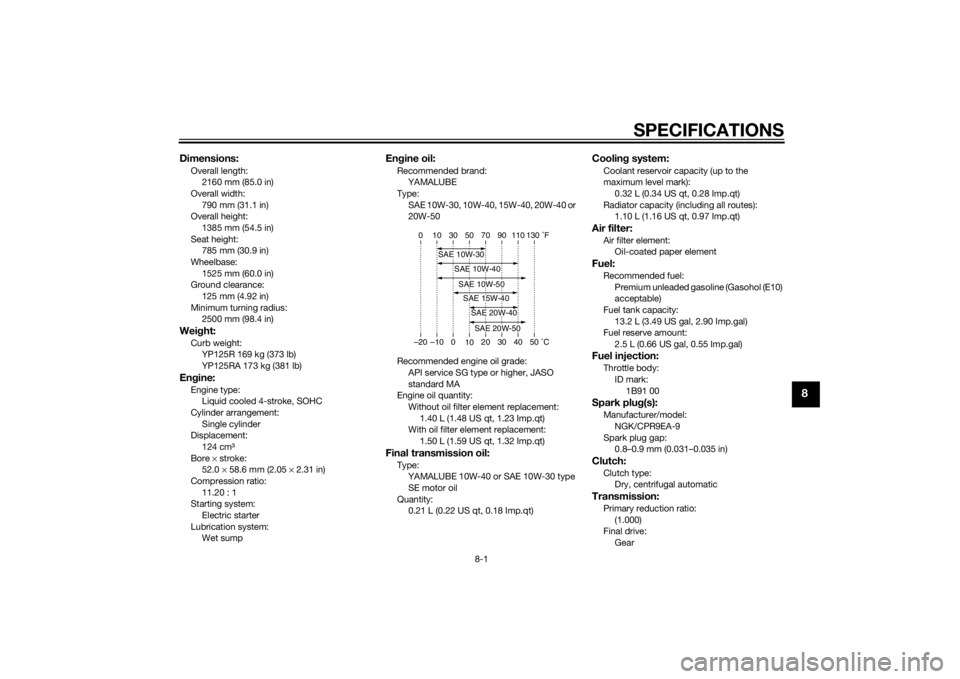
SAE 10W-30, 10W-40, 15W-40, 20W-40 or
20W-50
Recommended engine oil grade:
API service SG type or higher, JASO
standard MA
Engine oil quantity:
Without oil filter element replacement:
1.40 L (1.48 US qt, 1.23 Imp.qt)
With oil filter element replacement:
1.50 L (1.59 US qt, 1.32 Imp.qt)Final transmission oil:Type:
YAMALUBE 10W-40 or SAE 10W-30 type
SE motor oil
Quantity:
0.21 L (0.22 US qt, 0.18 Imp.qt)
Cooling system:Coolant reservoir capacity (up to the
maximum level mark):
0.32 L (0.34 US qt, 0.28 Imp.qt)
Radiator capacity (including all routes):
1.10 L (1.16 US qt, 0.97 Imp.qt)Air filter:Air filter element:
Oil-coated paper elementFuel:Recommended fuel:
Premium unleaded gasoline (Gasohol (E10)
acceptable)
Fuel tank capacity:
13.2 L (3.49 US gal, 2.90 Imp.gal)
Fuel reserve amount:
2.5 L (0.66 US gal, 0.55 Imp.gal)Fuel injection:Throttle body:
ID mark:
1B91 00Spark plug(s):Manufacturer/model:
NGK/CPR9EA-9
Spark plug gap:
0.8–0.9 mm (0.031–0.035 in)Clutch:Clutch type:
Dry, centrifugal automaticTransmission:Primary reduction ratio:
(1.000)
Final drive:
Gear
–20 –10 0
1020 30 40 50 �C 10 30 50 70 90 110 0 130 �F
SAE 10W-30
SAE 15W-40SAE 20W-40SAE 20W-50
SAE 10W-40SAE 10W-50
U2DME1E0.book Page 1 Wednesday, October 23, 2013 1:37 PM
Page 91 of 94

10-1
10
INDEX
AABS (for ABS models) .......................... 3-16
ABS warning light (for ABS models) ....... 3-4
Acceleration and deceleration ................ 5-3
Air filter and V-belt case air filter
elements ............................................. 6-16
Anti-theft alarm (optional) ..................... 3-13
Auxiliary light ........................................ 6-33BBattery .................................................. 6-27
Brake fluid, changing............................ 6-24
Brake fluid level, checking.................... 6-22
Brake lever, front .................................. 3-15
Brake lever, rear ................................... 3-15
Brake levers, lubricating ....................... 6-25
Braking ................................................... 5-3CCables, checking and lubricating ......... 6-24
Care ........................................................ 7-1
Catalytic converters.............................. 3-19
Centerstand and sidestand, checking
and lubricating ................................... 6-25
Coolant ................................................. 6-15DDimmer switch...................................... 3-14EEngine break-in ...................................... 5-4
Engine oil .............................................. 6-12
Engine trouble warning light ................... 3-4FFinal transmission oil ............................ 6-14
Front and rear brake lever free play,
checking ............................................. 6-21
Front and rear brake pads, checking ... 6-21Front fork, checking ............................. 6-26
Front turn signal light ........................... 6-31
Fuel ...................................................... 3-17
Fuel consumption, tips for reducing ...... 5-4
Fuel level warning light........................... 3-4
Fuel tank cap........................................ 3-17
Fuses, replacing ................................... 6-29
HHandlebar switches ............................. 3-14
Hazard switch ...................................... 3-14
Headlight bulb, replacing ..................... 6-30
High beam indicator light ....................... 3-4
Horn switch .......................................... 3-14IIdentification numbers ........................... 9-1
Ignition circuit cut-off system .............. 3-23
Immobilizer system ................................ 3-1
Immobilizer system indicator light ......... 3-5
Indicator lights and warning lights ......... 3-3LLicense plate light bulb, replacing ....... 6-32MMain switch/steering lock ...................... 3-2
Maintenance and lubrication, periodic... 6-4
Maintenance, emission control
system ................................................. 6-3
Matte color, caution ............................... 7-1
Model label............................................. 9-1
Multi-function meter unit ........................ 3-5PPanels, removing and installing ............. 6-8
Parking ................................................... 5-5
Part locations ......................................... 2-1
Pass switch .......................................... 3-14
SSafe-riding points ................................... 1-5
Safety information................................... 1-1
Seat....................................................... 3-19
Shock absorber assemblies,
adjusting ............................................. 3-21
Sidestand.............................................. 3-22
Spark plug, checking ............................ 6-10
Specifications ......................................... 8-1
Starting off .............................................. 5-2
Starting the engine ................................. 5-1
Start switch ........................................... 3-14
Steering, checking ................................ 6-27
Storage ................................................... 7-4
Storage compartments ......................... 3-20TTail/brake light ...................................... 6-31
Throttle grip and cable, checking and
lubricating ........................................... 6-24
Throttle grip free play, checking ........... 6-18
Tires ...................................................... 6-18
Tool kit .................................................... 6-2
Troubleshooting .................................... 6-33
Troubleshooting charts ......................... 6-34
Turn signal indicator lights...................... 3-3
Turn signal light bulb (rear),
replacing ............................................. 6-31
Turn signal switch ................................. 3-14VValve clearance..................................... 6-18
Vehicle identification number ................. 9-1WWheel bearings, checking .................... 6-27
Wheels .................................................. 6-20
U2DME1E0.book Page 1 Wednesday, October 23, 2013 1:37 PM