seat adjustment YAMAHA XMAX 125 2014 Owners Manual
[x] Cancel search | Manufacturer: YAMAHA, Model Year: 2014, Model line: XMAX 125, Model: YAMAHA XMAX 125 2014Pages: 94, PDF Size: 8.21 MB
Page 6 of 94

TABLE OF CONTENTSSAFETY INFORMATION.................. 1-1
Further safe-riding points ............... 1-5
DESCRIPTION.................................. 2-1
Left view ......................................... 2-1
Right view ....................................... 2-2
Controls and instruments ............... 2-3
INSTRUMENT AND CONTROL
FUNCTIONS...................................... 3-1
Immobilizer system......................... 3-1
Main switch/steering lock............... 3-2
Indicator lights and warning
lights............................................ 3-3
Multi-function meter unit ................ 3-5
Anti-theft alarm (optional) ............. 3-13
Handlebar switches ...................... 3-14
Front brake lever .......................... 3-15
Rear brake lever ........................... 3-15
ABS (for ABS models) .................. 3-16
Fuel tank cap ................................ 3-17
Fuel ............................................... 3-17
Catalytic converters...................... 3-19
Seat .............................................. 3-19
Storage compartments................. 3-20
Adjusting the shock absorber
assemblies ................................ 3-21
Sidestand ..................................... 3-22
Ignition circuit cut-off system ....... 3-23FOR YOUR SAFETY –
PRE-OPERATION CHECKS............. 4-1
OPERATION AND IMPORTANT
RIDING POINTS................................ 5-1
Starting the engine .......................... 5-1
Starting off ...................................... 5-2
Acceleration and deceleration ........ 5-3
Braking ............................................ 5-3
Tips for reducing fuel
consumption ................................ 5-4
Engine break-in ............................... 5-4
Parking ............................................ 5-5
PERIODIC MAINTENANCE AND
ADJUSTMENT................................... 6-1
Owner’s tool kit ............................... 6-2
Periodic maintenance chart for the
emission control system .............. 6-3
General maintenance and
lubrication chart ........................... 6-4
Removing and installing panels ...... 6-8
Checking the spark plug ............... 6-10
Engine oil....................................... 6-12
Final transmission oil..................... 6-14
Coolant.......................................... 6-15
Air filter and V-belt case air filter
elements and check hoses ........ 6-16
Checking the throttle grip free
play ............................................ 6-18
Valve clearance ............................. 6-18Tires .............................................. 6-18
Cast wheels .................................. 6-20
Checking the front and rear brake
lever free play ............................ 6-21
Checking the front and rear brake
pads .......................................... 6-21
Checking the brake fluid level ...... 6-22
Changing the brake fluid .............. 6-24
Checking and lubricating the
cables ........................................ 6-24
Checking and lubricating the
throttle grip and cable ............... 6-24
Lubricating the front and rear
brake levers ............................... 6-25
Checking and lubricating the
centerstand and sidestand........ 6-25
Checking the front fork ................. 6-26
Checking the steering................... 6-27
Checking the wheel bearings ....... 6-27
Battery .......................................... 6-27
Replacing the fuses ...................... 6-29
Replacing a headlight bulb ........... 6-30
Tail/brake light .............................. 6-31
Front turn signal light .................... 6-31
Replacing a rear turn signal light
bulb ........................................... 6-31
Replacing the license plate light
bulb ........................................... 6-32
Auxiliary light ................................ 6-33
Troubleshooting............................ 6-33
Troubleshooting charts................. 6-34U2DME1E0.book Page 1 Wednesday, October 23, 2013 1:37 PM
Page 49 of 94
PERIODIC MAINTENANCE AND ADJUSTMENT
6-2
6
EAU17303
Emission controls not only function to
ensure cleaner air, but are also vital to
proper engine operation and maximum
performance. In the following periodic
maintenance charts, the services relat-
ed to emissions control are grouped
separately. These services require
specialized data, knowledge, and
equipment. Maintenance, replace-
ment, or repair of the emission control
devices and systems may be per-
formed by any repair establishment or
individual that is certified (if applicable).
Yamaha dealers are trained and
equipped to perform these particular
services.
EAU17382
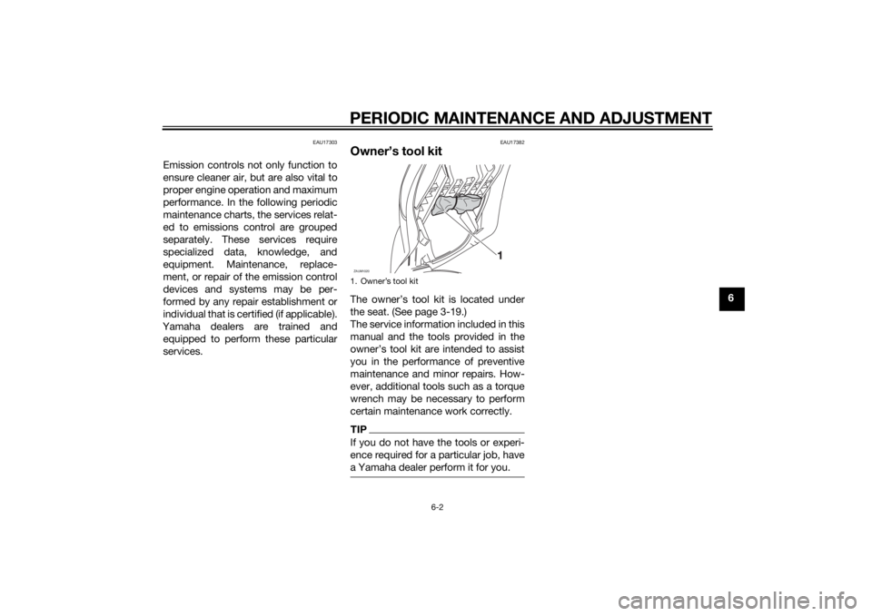
Owner’s tool kitThe owner’s tool kit is located under
the seat. (See page 3-19.)
The service information included in this
manual and the tools provided in the
owner’s tool kit are intended to assist
you in the performance of preventive
maintenance and minor repairs. How-
ever, additional tools such as a torque
wrench may be necessary to perform
certain maintenance work correctly.TIPIf you do not have the tools or experi-
ence required for a particular job, have
a Yamaha dealer perform it for you.1. ZAUM1020
U2DME1E0.book Page 2 Wednesday, October 23, 2013 1:37 PM
Page 57 of 94
PERIODIC MAINTENANCE AND ADJUSTMENT
6-10
6
TIPTo install the quick fastener, push the
center pin out so that it will protrude
from the fastener head, insert the fas-
tener into the under cowling, and then
push the protruding pin in until it is
flush with the fastener head.
EAUM3360
Checking the spark plugThe spark plug is an important engine
component, which is easy to check.
Since heat and deposits will cause any
spark plug to slowly erode, the spark
plug should be removed and checked
in accordance with the periodic main-
tenance and lubrication chart. In addi-
tion, the condition of the spark plug
can reveal the condition of the engine.
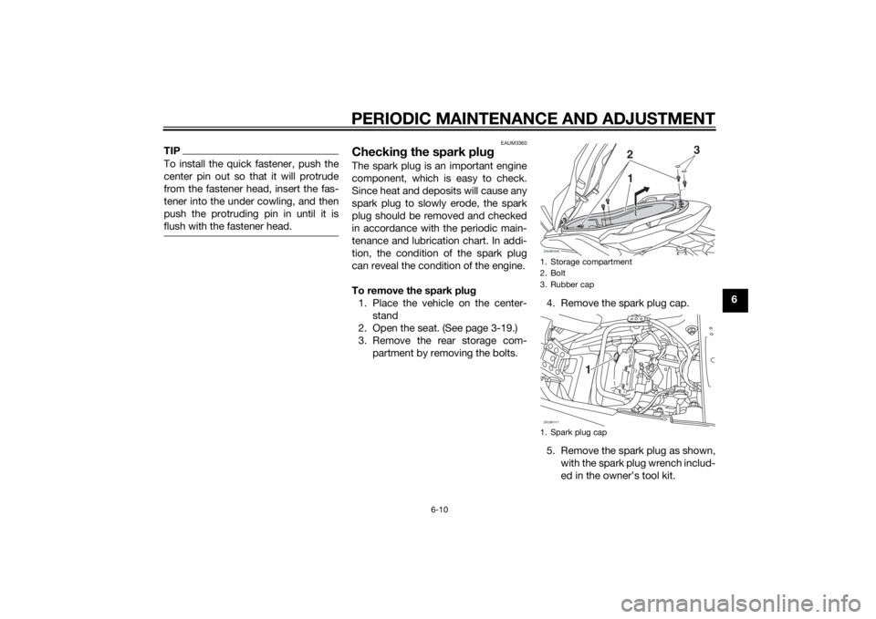
To remove the spark plug
1. Place the vehicle on the center-
stand
2. Open the seat. (See page 3-19.)
3. Remove the rear storage com-
partment by removing the bolts.4. Remove the spark plug cap.
5. Remove the spark plug as shown,
with the spark plug wrench includ-
ed in the owner’s tool kit.
1. Storage compartment
2. Bolt
3. Rubber cap
1. Spark plug capZAUM1040
23
1
ZAUM1117
1
U2DME1E0.book Page 10 Wednesday, October 23, 2013 1:37 PM
Page 58 of 94
PERIODIC MAINTENANCE AND ADJUSTMENT
6-11
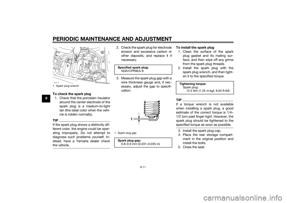
6To check the spark plug
1. Check that the porcelain insulator
around the center electrode of the
spark plug is a medium-to-light
tan (the ideal color when the vehi-
cle is ridden normally).
TIPIf the spark plug shows a distinctly dif-
ferent color, the engine could be oper-
ating improperly. Do not attempt to
diagnose such problems yourself. In-
stead, have a Yamaha dealer check
the vehicle.
2. Check the spark plug for electrode
erosion and excessive carbon or
other deposits, and replace it if
necessary.
3. Measure the spark plug gap with a
wire thickness gauge and, if nec-
essary, adjust the gap to specifi-
cation.To install the spark plug
1. Clean the surface of the spark
plug gasket and its mating sur-
face, and then wipe off any grime
from the spark plug threads.
2. Install the spark plug with the
spark plug wrench, and then tight-
en it to the specified torque.
TIPIf a torque wrench is not available
when installing a spark plug, a good
estimate of the correct torque is 1/4…
1/2 turn past finger tight. However, the
spark plug should be tightened to the
specified torque as soon as possible.3. Install the spark plug cap.
4. Place the rear storage compart-
ment in the original position and
install the bolts.
5. Close the seat.
1. Spark plug wrenchZAUM1118
1
Specified spark plug:
NGK/CPR9EA-91. Spark plug gapSpark plug gap:
0.8–0.9 mm (0.031–0.035 in)
1
Tightening torque:
Spark plug:
12.5 Nm (1.25 m·kgf, 9.04 ft·lbf)
U2DME1E0.book Page 11 Wednesday, October 23, 2013 1:37 PM
Page 60 of 94
PERIODIC MAINTENANCE AND ADJUSTMENT
6-13
6
TIPSkip steps 5–9 if the oil filter element is
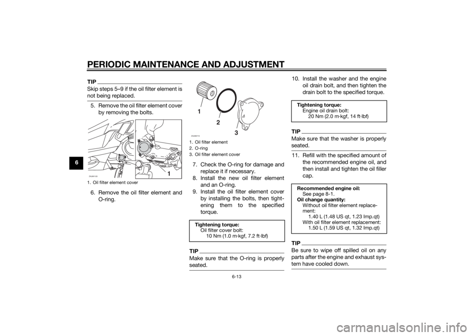
not being replaced.5. Remove the oil filter element cover
by removing the bolts.
6. Remove the oil filter element and
O-ring.7. Check the O-ring for damage and
replace it if necessary.
8. Install the new oil filter element
and an O-ring.
9. Install the oil filter element cover
by installing the bolts, then tight-
ening them to the specified
torque.
TIPMake sure that the O-ring is properly
seated.
10. Install the washer and the engine
oil drain bolt, and then tighten the
drain bolt to the specified torque.TIPMake sure that the washer is properly
seated.11. Refill with the specified amount of
the recommended engine oil, and
then install and tighten the oil filler
cap.TIPBe sure to wipe off spilled oil on any
parts after the engine and exhaust sys-
tem have cooled down.
1. Oil filter element coverZAUM1120
1
1. Oil filter element
2. O-ring
3. Oil filter element coverTightening torque:
Oil filter cover bolt:
10 Nm (1.0 m·kgf, 7.2 ft·lbf)1
2
3
ZAUM0712
Tightening torque:
Engine oil drain bolt:
20 Nm (2.0 m·kgf, 14 ft·lbf)
Recommended engine oil:
See page 8-1.
Oil change quantity:
Without oil filter element replace-
ment:
1.40 L (1.48 US qt, 1.23 Imp.qt)
With oil filter element replacement:
1.50 L (1.59 US qt, 1.32 Imp.qt)
U2DME1E0.book Page 13 Wednesday, October 23, 2013 1:37 PM
Page 64 of 94
PERIODIC MAINTENANCE AND ADJUSTMENT
6-17
63. Pull the air filter element out.
4. Insert a new air filter element into
the air filter case.
5. Install the air filter case cover by
installing the screws.
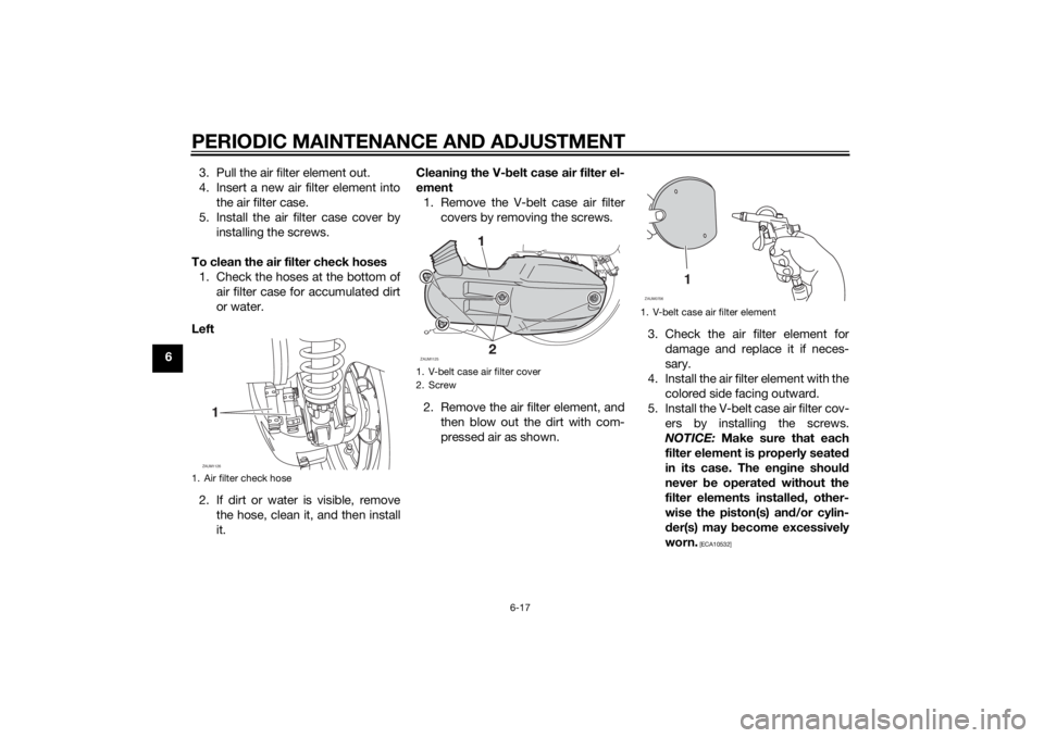
To clean the air filter check hoses
1. Check the hoses at the bottom of
air filter case for accumulated dirt
or water.
Left
2. If dirt or water is visible, remove
the hose, clean it, and then install
it.Cleaning the V-belt case air filter el-
ement
1. Remove the V-belt case air filter
covers by removing the screws.
2. Remove the air filter element, and
then blow out the dirt with com-
pressed air as shown.3. Check the air filter element for
damage and replace it if neces-
sary.
4. Install the air filter element with the
colored side facing outward.
5. Install the V-belt case air filter cov-
ers by installing the screws.
NOTICE: Make sure that each
filter element is properly seated
in its case. The engine should
never be operated without the
filter elements installed, other-
wise the piston(s) and/or cylin-
der(s) may become excessively
worn.
[ECA10532]
1. Air filter check hoseZAUM11261
1. V-belt case air filter cover
2. ScrewZAUM1125
1. V-belt case air filter element
1
ZAUM0706
U2DME1E0.book Page 17 Wednesday, October 23, 2013 1:37 PM
Page 78 of 94
PERIODIC MAINTENANCE AND ADJUSTMENT
6-31
6
EAU24182
Tail/brake lightThis model is equipped with an LED-
type tail/brake light.
If the tail/brake light does not come on,
have a Yamaha dealer check it.
EAU39881
Front turn signal lightIf a front turn signal light does not
come on, have a Yamaha dealer check
its electrical circuit or replace the bulb.
EAUM3062
Replacing a rear turn signal
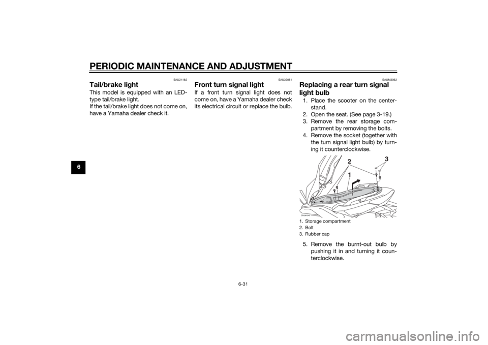
light bulb1. Place the scooter on the center-
stand.
2. Open the seat. (See page 3-19.)
3. Remove the rear storage com-
partment by removing the bolts.
4. Remove the socket (together with
the turn signal light bulb) by turn-
ing it counterclockwise.
5. Remove the burnt-out bulb by
pushing it in and turning it coun-
terclockwise.1. Storage compartment
2. Bolt
3. Rubber capZAUM1040
23
1
U2DME1E0.book Page 31 Wednesday, October 23, 2013 1:37 PM
Page 79 of 94
PERIODIC MAINTENANCE AND ADJUSTMENT
6-32
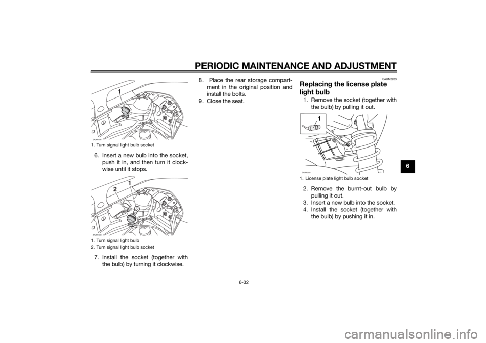
6 6. Insert a new bulb into the socket,
push it in, and then turn it clock-
wise until it stops.
7. Install the socket (together with
the bulb) by turning it clockwise.8. Place the rear storage compart-
ment in the original position and
install the bolts.
9. Close the seat.
EAUM2203
Replacing the license plate
light bulb1. Remove the socket (together with
the bulb) by pulling it out.
2. Remove the burnt-out bulb by
pulling it out.
3. Insert a new bulb into the socket.
4. Install the socket (together with
the bulb) by pushing it in.
1. Turn signal light bulb socket
1. Turn signal light bulb
2. Turn signal light bulb socketZAUM1038
1
ZAUM1039
1
2
1. License plate light bulb socketZAUM0681
1
U2DME1E0.book Page 32 Wednesday, October 23, 2013 1:37 PM