brake YAMAHA XMAX 125 2016 Owners Manual
[x] Cancel search | Manufacturer: YAMAHA, Model Year: 2016, Model line: XMAX 125, Model: YAMAHA XMAX 125 2016Pages: 96, PDF Size: 8.11 MB
Page 5 of 96

Table of contents
Safety information............................1-1
Further safe-riding points ................1-5
Description........................................2-1
Left view ..........................................2-1
Right view........................................2-2
Controls and instruments ................2-3
Instrument and control functions....3-1
Immobilizer system .........................3-1
Main switch/steering lock ...............3-2
Indicator lights and warning
lights ............................................3-4
Multi-function meter unit .................3-6
Handlebar switches.......................3-14
Front brake lever ...........................3-15
Rear brake lever ............................3-16
ABS (for ABS models) ...................3-16
Fuel tank cap.................................3-17
Fuel................................................3-18
Catalytic converters .....................3-19
Seat ...............................................3-20
Storage compartments .................3-21
Adjusting the shock absorber
assemblies .................................3-22
Sidestand ......................................3-23
Ignition circuit cut-off system........3-24
For your safety – pre-operation
checks...............................................4-1
Operation and important riding
points.................................................5-1
Starting the engine ..........................5-2
Starting off.......................................5-3
Acceleration and deceleration.........5-3
Braking ............................................5-4
Tips for reducing fuel
consumption ................................5-5
Engine break-in ...............................5-5
Parking ............................................5-6
Periodic maintenance and
adjustment........................................6-1
Owner’s tool kit ...............................6-2Periodic maintenance chart for the
emission control system.............. 6-3
General maintenance and
lubrication chart........................... 6-4
Removing and installing panels ...... 6-7
Checking the spark plug ................. 6-9
Engine oil ...................................... 6-10
Final transmission oil .................... 6-13
Coolant ......................................... 6-14
Air filter and V-belt case air filter
elements and check hoses........ 6-15
Checking the throttle grip free
play ............................................ 6-17
Valve clearance ............................. 6-17
Tires .............................................. 6-18
Cast wheels .................................. 6-20
Checking the front and rear brake
lever free play ............................ 6-20
Checking the front and rear brake
pads........................................... 6-21
Checking the brake fluid level....... 6-22
Changing the brake fluid............... 6-23
Checking and lubricating the
cables ........................................ 6-24
Checking and lubricating the
throttle grip and cable ............... 6-24
Lubricating the front and rear
brake levers ............................... 6-25
Checking and lubricating the
centerstand and sidestand ........ 6-25
Checking the front fork ................. 6-26
Checking the steering ................... 6-26
Checking the wheel bearings ....... 6-27
Battery .......................................... 6-27
Replacing the fuses ...................... 6-29
Replacing a headlight bulb ........... 6-31
Auxiliary lights ............................... 6-31
Tail/brake light .............................. 6-32
Front turn signal light .................... 6-32
Replacing a rear turn signal light
bulb............................................ 6-33
Replacing the license plate light
bulb............................................ 6-34
Troubleshooting ............................ 6-34
Troubleshooting charts ................. 6-35
U2DME2E0.book Page 1 Tuesday, June 30, 2015 11:38 AM
Page 11 of 96

Safety information
1-5
1 Aftermarket Tires and Rims
The tires and rims that came with your
scooter were designed to match the
performance capabilities and to pro-
vide the best combination of handling,
braking, and comfort. Other tires, rims,
sizes, and combinations may not be
appropriate. Refer to page 6-18 for tire
specifications and more information on
replacing your tires.
Transporting the Scooter
Be sure to observe following instruc-
tions before transporting the scooter in
another vehicle.
Remove all loose items from the
scooter.
Point the front wheel straight
ahead on the trailer or in the truck
bed, and choke it in a rail to pre-
vent movement.
Secure the scooter with tie-downs
or suitable straps that are at-
tached to solid parts of the scoot-
er, such as the frame or upper
front fork triple clamp (and not, for
example, to rubber-mounted han-
dlebars or turn signals, or parts
that could break). Choose the lo-
cation for the straps carefully so
the straps will not rub against
painted surfaces during transport.
The suspension should be com-
pressed somewhat by the tie-
downs, if possible, so that the
scooter will not bounce exces-
sively during transport.
EAU57600
Further safe-riding points
Be sure to signal clearly when
making turns.
Braking can be extremely difficult
on a wet road. Avoid hard braking,
because the scooter could slide.
Apply the brakes slowly when
stopping on a wet surface.
Slow down as you approach a
corner or turn. Once you have
completed a turn, accelerate
slowly.
Be careful when passing parked
cars. A driver might not see you
and open a door in your path.
Railroad crossings, streetcar rails,
iron plates on road construction
sites, and manhole covers be-
come extremely slippery when
wet. Slow down and cross them
with caution. Keep the scooter up-
right, otherwise it could slide out
from under you.
The brake pads or linings could
get wet when you wash the scoot-
er. After washing the scooter,
check the brakes before riding.
Always wear a helmet, gloves,
trousers (tapered around the cuff
and ankle so they do not flap), and
a brightly colored jacket.
Do not carry too much luggage on
the scooter. An overloaded scoot-
er is unstable. Use a strong cord
to secure any luggage to the carri-
er (if equipped). A loose load will
affect the stability of the scooter
and could divert your attention
from the road. (See page 1-3.)
U2DME2E0.book Page 5 Tuesday, June 30, 2015 11:38 AM
Page 12 of 96
Description
2-1
2
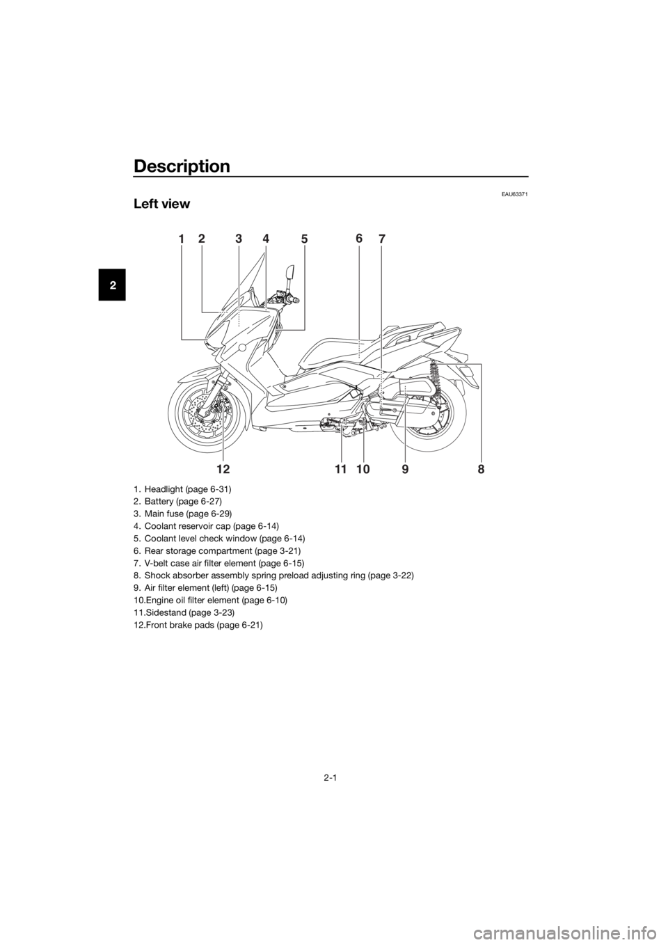
EAU63371
Left view
15243
7 6
98 10 11
12
1. Headlight (page 6-31)
2. Battery (page 6-27)
3. Main fuse (page 6-29)
4. Coolant reservoir cap (page 6-14)
5. Coolant level check window (page 6-14)
6. Rear storage compartment (page 3-21)
7. V-belt case air filter element (page 6-15)
8. Shock absorber assembly spring preload adjusting ring (page 3-22)
9. Air filter element (left) (page 6-15)
10.Engine oil filter element (page 6-10)
11.Sidestand (page 3-23)
12.Front brake pads (page 6-21)
U2DME2E0.book Page 1 Tuesday, June 30, 2015 11:38 AM
Page 14 of 96
Description
2-3
2
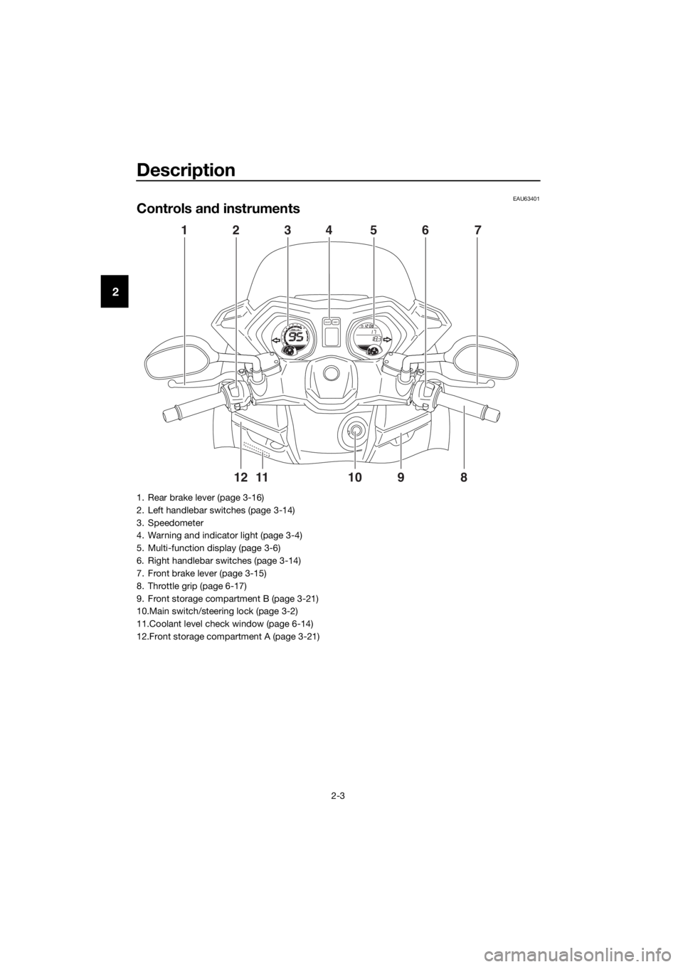
EAU63401
Controls and instruments
98765432111 10
120
1000r/minx
E
FCH
FSELECTRESET
417 5 362
891011 12
1. Rear brake lever (page 3-16)
2. Left handlebar switches (page 3-14)
3. Speedometer
4. Warning and indicator light (page 3-4)
5. Multi-function display (page 3-6)
6. Right handlebar switches (page 3-14)
7. Front brake lever (page 3-15)
8. Throttle grip (page 6-17)
9. Front storage compartment B (page 3-21)
10.Main switch/steering lock (page 3-2)
11.Coolant level check window (page 6-14)
12.Front storage compartment A (page 3-21)
U2DME2E0.book Page 3 Tuesday, June 30, 2015 11:38 AM
Page 18 of 96
Instrument and control functions
3-4
3
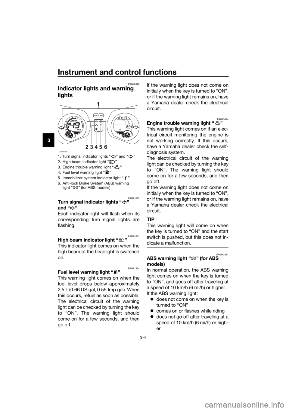
EAU49398
Indicator lights and warning
lights
EAU11032Turn signal indicator lights “ ”
and“”
Each indicator light will flash when its
corresponding turn signal lights are
flashing.
EAU11081High beam indicator light “ ”
This indicator light comes on when the
high beam of the headlight is switched
on.
EAU11354Fuel level warning light “ ”
This warning light comes on when the
fuel level drops below approximately
2.5 L (0.66 US gal, 0.55 Imp.gal). When
this occurs, refuel as soon as possible.
The electrical circuit of the warning
light can be checked by turning the key
to “ON”. The warning light should
come on for a few seconds, and then
go off.If the warning light does not come on
initially when the key is turned to “ON”,
or if the warning light remains on, have
a Yamaha dealer check the electrical
circuit.
EAU43024Engine trouble warning light “ ”
This warning light comes on if an elec-
trical circuit monitoring the engine is
not working correctly. If this occurs,
have a Yamaha dealer check the self-
diagnosis system.
The electrical circuit of the warning
light can be checked by turning the key
to “ON”. The warning light should
come on for a few seconds, and then
go off.
If the warning light does not come on
initially when the key is turned to “ON”,
or if the warning light remains on, have
a Yamaha dealer check the electrical
circuit.
TIP
This warning light will come on when
switch is pushed, but this does not in-
dicate a malfunction.
EAUM3381ABS warning light “ ” (for ABS
models)
In normal operation, the ABS warning
light comes on when the key is turned
to “ON”, and goes off after traveling at
a speed of 10 km/h (6 mi/h) or higher.
If the ABS warning light:
does not come on when the key is
turned to “ON”
comes on or flashes while riding
does not go off after traveling at a
speed of 10 km/h (6 mi/h) or high-
er
1. Turn signal indicator lights “ ” and “ ”
2. High beam indicator light “ ”
3. Engine trouble warning light “ ”
4. Fuel level warning light “ ”
5. Immobilizer system indicator light “ ”
6. Anti-lock Brake System (ABS) warning
light “ ” (for ABS models)
ZAUM109823456
98765432111 10
12
0
1000r/minx
km/h
E
FCH
kmOdoOdoSELECTRESET
11
ABS
ABS
U2DME2E0.book Page 4 Tuesday, June 30, 2015 11:38 AM
Page 19 of 96
Instrument and control functions
3-5
3 The ABS may not work correctly. If any
of the above occurs, have a Yamaha
dealer check the system as soon as
possible. (See page 3-16 for an expla-
nation of the ABS.)
WARNING
EWA16041
If the ABS warning light does not go
off after traveling at a speed of 10
km/h (6 mi/h) or higher, or if the
warning light comes on or flashes
while riding, the brake system re-
verts to conventional braking. If ei-
ther of the above occurs, or if the
warning light does not come on at
all, use extra caution to avoid possi-
ble wheel lock during emergency
braking. Have a Yamaha dealer
check the brake system and electri-
cal circuits as soon as possible.
TIP
The ABS warning light may come on
while accelerating the engine with the
scooter on its centerstand, but this
does not indicate a malfunction.
EAU26879Immobilizer system indicator
light “ ”
When the key is turned to “OFF” and
30 seconds have passed, the indicator
light will start flashing indicating the im-
mobilizer system is enabled. After 24
hours have passed, the indicator light
will stop flashing, however the immobi-
lizer system is still enabled.
The electrical circuit of the indicator
light can be checked by turning the key
to “ON”. The indicator light should
come on for a few seconds, and then
go off.If the indicator light does not come on
initially when the key is turned to “ON”,
or if the indicator light remains on, have
a Yamaha dealer check the electrical
circuit.
The self-diagnosis device also detects
problems in the immobilizer system
circuits. (See page 3-13 for an explana-
tion of the self-diagnosis device.)
U2DME2E0.book Page 5 Tuesday, June 30, 2015 11:38 AM
Page 28 of 96
Instrument and control functions
3-14
3
EAU1234H
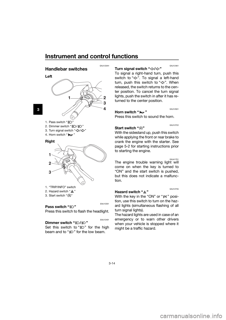
Handlebar switches
Left
Right
EAU12351Pass switch “ ”
Press this switch to flash the headlight.
EAU12401Dimmer switch “ / ”
Set this switch to “ ” for the high
beam and to “ ” for the low beam.
EAU12461Turn signal switch “ / ”
To signal a right-hand turn, push this
switch to “ ”. To signal a left-hand
turn, push this switch to “ ”. When
released, the switch returns to the cen-
ter position. To cancel the turn signal
lights, push the switch in after it has re-
turned to the center position.
EAU12501Horn switch “ ”
Press this switch to sound the horn.
EAU12722Start switch “ ”
With the sidestand up, push this switch
while applying the front or rear brake to
crank the engine with the starter. See
page 5-2 for starting instructions prior
to starting the engine.
EAU41701The engine trouble warning light will
come on when the key is turned to
“ON” and the start switch is pushed,
but this does not indicate a malfunc-
tion.
EAU12735Hazard switch “ ”
With the key in the “ON” or “ ” posi-
tion, use this switch to turn on the haz-
ard lights (simultaneous flashing of all
turn signal lights).
The hazard lights are used in case of an
emergency or to warn other drivers
when your vehicle is stopped where it
might be a traffic hazard.
1. Pass switch “ ”
2. Dimmer switch “ / ”
3. Turn signal switch “ / ”
4. Horn switch “ ”
1. “TRIP/INFO” switch
2. Hazard switch “ ”
3. Start switch “ ”
I
N
FOTRI
P
1
3 2
U2DME2E0.book Page 14 Tuesday, June 30, 2015 11:38 AM
Page 29 of 96
Instrument and control functions
3-15
3
NOTICE
ECA10062
Do not use the hazard lights for an
extended length of time with the en-
gine not running, otherwise the bat-
tery may discharge.
EAUM3720Trip/info switch “TRIP/INFO”
This switch is used to make setting and
display changes in the multi-function
meter unit. See page 3-6 for more in-
formation.
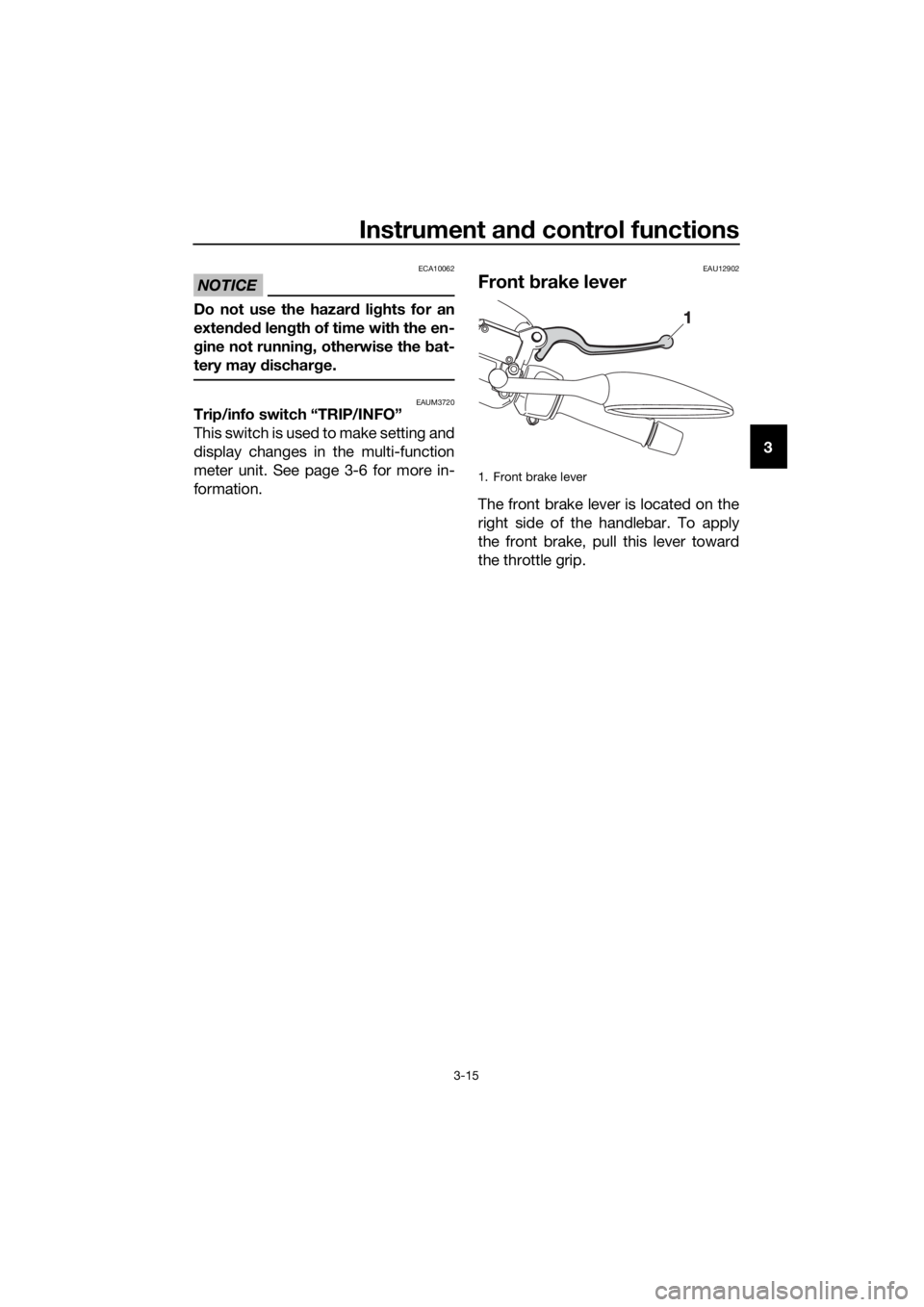
EAU12902
Front brake lever
The front brake lever is located on the
right side of the handlebar. To apply
the front brake, pull this lever toward
the throttle grip.
1. Front brake lever
U2DME2E0.book Page 15 Tuesday, June 30, 2015 11:38 AM
Page 30 of 96
Instrument and control functions
3-16
3
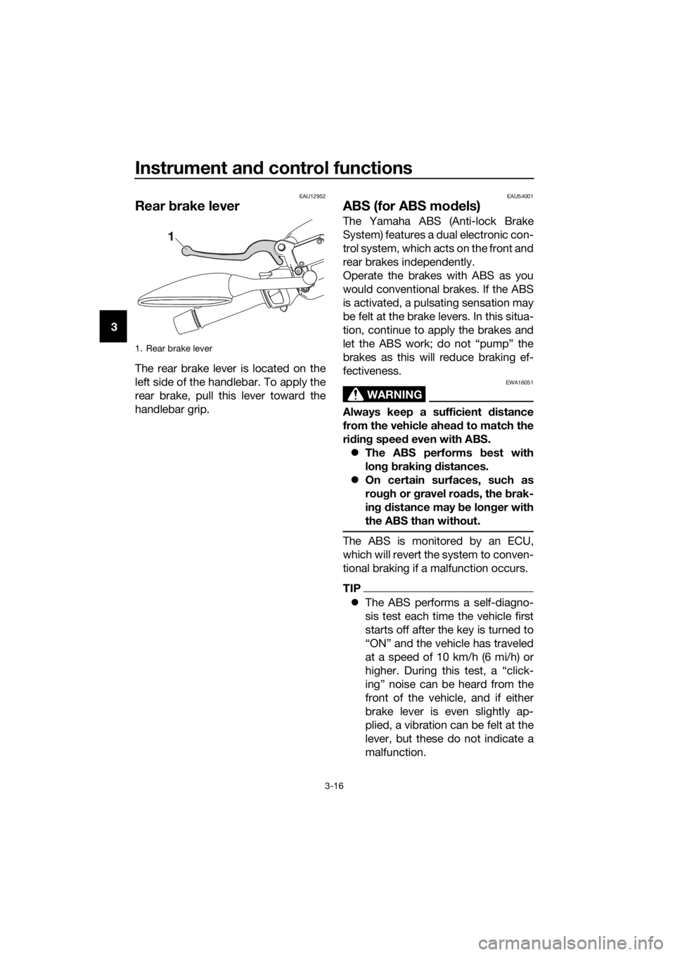
EAU12952
Rear brake lever
The rear brake lever is located on the
left side of the handlebar. To apply the
rear brake, pull this lever toward the
handlebar grip.
EAU54001
ABS (for ABS models)
The Yamaha ABS (Anti-lock Brake
System) features a dual electronic con-
trol system, which acts on the front and
rear brakes independently.
Operate the brakes with ABS as you
would conventional brakes. If the ABS
is activated, a pulsating sensation may
be felt at the brake levers. In this situa-
tion, continue to apply the brakes and
let the ABS work; do not “pump” the
brakes as this will reduce braking ef-
fectiveness.
WARNING
EWA16051
Always keep a sufficient distance
from the vehicle ahead to match the
riding speed even with ABS.
The ABS performs best with
long braking distances.
On certain surfaces, such as
rough or gravel roads, the brak-
ing distance may be longer with
the ABS than without.
The ABS is monitored by an ECU,
which will revert the system to conven-
tional braking if a malfunction occurs.
TIP
The ABS performs a self-diagno-
sis test each time the vehicle first
starts off after the key is turned to
“ON” and the vehicle has traveled
at a speed of 10 km/h (6 mi/h) or
higher. During this test, a “click-
ing” noise can be heard from the
front of the vehicle, and if either
brake lever is even slightly ap-
plied, a vibration can be felt at the
lever, but these do not indicate a
malfunction.
1. Rear brake lever
U2DME2E0.book Page 16 Tuesday, June 30, 2015 11:38 AM
Page 31 of 96
Instrument and control functions
3-17
3 This ABS has a test mode which
allows the owner to experience
the pulsation at the brake levers
when the ABS is operating. How-
ever, special tools are required, so
please consult your Yamaha deal-
er when performing this test.
NOTICE
ECA16121
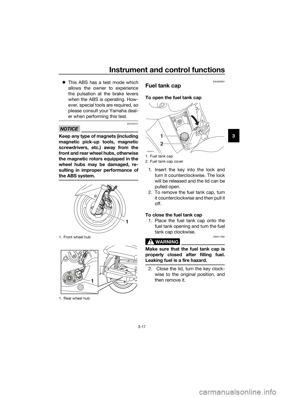
Keep any type of magnets (including
magnetic pick-up tools, magnetic
screwdrivers, etc.) away from the
front and rear wheel hubs, otherwise
the magnetic rotors equipped in the
wheel hubs may be damaged, re-
sulting in improper performance of
the ABS system.
EAUM2991
Fuel tank cap
To open the fuel tank cap
1. Insert the key into the lock and
turn it counterclockwise. The lock
will be released and the lid can be
pulled open.
2. To remove the fuel tank cap, turn
it counterclockwise and then pull it
off.
To close the fuel tank cap
1. Place the fuel tank cap onto the
fuel tank opening and turn the fuel
tank cap clockwise.
WARNING
EWA11092
Make sure that the fuel tank cap is
properly closed after filling fuel.
Leaking fuel is a fire hazard.
2. Close the lid, turn the key clock-
wise to the original position, and
then remove it.
1. Front wheel hub
1. Rear wheel hub
1
1
1. Fuel tank cap
2. Fuel tank cap cover
ZAUM1014
1
2
U2DME2E0.book Page 17 Tuesday, June 30, 2015 11:38 AM