change wheel YAMAHA XMAX 300 2021 Owners Manual
[x] Cancel search | Manufacturer: YAMAHA, Model Year: 2021, Model line: XMAX 300, Model: YAMAHA XMAX 300 2021Pages: 114, PDF Size: 4.65 MB
Page 28 of 114

Instrument and control functions
4-1
4
EAU4939N
In dicator li ghts an d warnin g
li g hts
EAU11032
Turn si gnal in dicator li ghts “ ”
an d“”
Each indicator light will flash when its
corresponding turn signal lights are
flashing.
EAU11081
Hi gh beam in dicator li ght “ ”
This indicator light comes on when the
high beam of the headlight is switched
on.
EAU88711
Malfunction in dicator li ght
(MIL) “ ”
This light comes on or flashes if a prob-
lem is detected in the engine or other
vehicle control system. If this occurs,
have a Yamaha dealer check the on-
board diagnostic system. The electri-
cal circuit of the warning light can be
checked by vehicle power on. The light
should come on for a few seconds,
and then go off. If the light does not
come on initially when the vehicle pow-
er on, or if the light remains on, have a
Yamaha dealer check the vehicle.NOTICE
ECA26820
If the MIL starts flashin g, re duce en-
g ine spee d to prevent exhaust sys-
tem damag e.
TIPThe engine is sensitively controlled for
the on-board diagnostic system to de-
tect deterioration and malfunction of
the emission control system. Due to
this specification, the MIL may come
on or flash for vehicle modifications,
lack of maintenance, or excessive or
improper use of the vehicle. To prevent
this, observe these precautions.
Do not attempt to modify the soft-
ware of the engine control unit.
Do not add any electrical acces-
sories that interfere with engine
control.
Do not use aftermarket accesso-
ries or parts such as suspension,
spark plugs, injectors, exhaust
system, etc.
Do not change drivetrain specifi-
cations (chain, sprockets, wheels,
tires, etc.).
Do not remove or alter the O2 sen-
sor, air induction system, or ex-
haust parts (catalysts or EXUP,
etc.).
Maintain proper V-belt and drive
belt (if equipped).
1. Left turn signal indicator light “ ”
2. Right turn signal indicator light “ ”
3. High beam indicator light “ ”
4. Anti-lock Brake System (ABS) warning
light “ ”
5. Malfunction indicator light “ ”
6. Traction control system indicator light “ ”
7. Smart key system indicator light “ ”ZAUM1548
1
2
ABS
UBBAE0E0.book Page 1 Thursday, September 24, 2020 3:19 PM
Page 42 of 114

Instrument and control functions
4-15
4
EAU78611
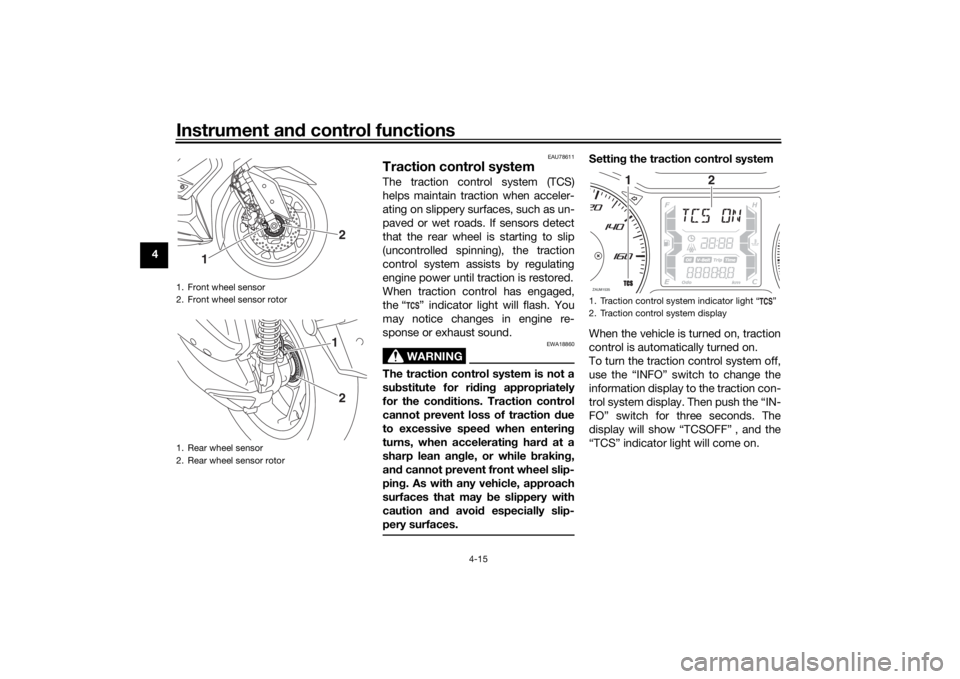
Traction control systemThe traction control system (TCS)
helps maintain traction when acceler-
ating on slippery surfaces, such as un-
paved or wet roads. If sensors detect
that the rear wheel is starting to slip
(uncontrolled spinning), the traction
control system assists by regulating
engine power until traction is restored.
When traction control has engaged,
the “ ” indicator light will flash. You
may notice changes in engine re-
sponse or exhaust sound.
WARNING
EWA18860
The traction control system is not a
su bstitute for rid ing appropriately
for the con ditions. Traction control
cannot prevent loss of traction due
to excessive speed when entering
turns, when acceleratin g har d at a
sharp lean an gle, or while b raking,
an d cannot prevent front wheel slip-
pin g. As with any vehicle, approach
surfaces that may be slippery with
caution an d avoi d especially slip-
pery surfaces.
Settin g the traction control system
When the vehicle is turned on, traction
control is automatically turned on.
To turn the traction control system off,
use the “INFO” switch to change the
information display to the traction con-
trol system display. Then push the “IN-
FO” switch for three seconds. The
display will show “TCSOFF” , and the
“TCS” indicator light will come on.
1. Front wheel sensor
2. Front wheel sensor rotor
1. Rear wheel sensor
2. Rear wheel sensor rotor
2
1
21
1. Traction control system indicator light “ ”
2. Traction control system displayZAUM1535
1
2
UBBAE0E0.book Page 15 Thursday, September 24, 2020 3:19 PM
Page 66 of 114

Periodic maintenance an d a djustment
7-4
7
EAU71353
General maintenance an d lu brication chartNO. ITEM CHECK OR MAINTENANCE JOB ODOMETER READING
ANNUAL
CHECK
1000 km
(600 mi) 10000 km
(6000 mi) 20000 km
(12000 mi) 30000 km
(18000 mi) 40000 km
(24000 mi)
1 *Dia
gnostic system
check • Perform dynamic inspection us-
ing Yamaha diagnostic tool.
• Check the error codes. √√√√√√
2 *Air filter element • Replace. √√
3 *Pre air filter element • Clean. √√
4 *Su
b air filter ele-
ment • Replace.
√√
5 Air filter case check
hose
• Clean.
√√√√√
6 *V-
belt case air filter
element • Clean.
• Replace if necessary.
√√√√√
7 *Front brake • Check operation, fluid level, and
for fluid leakage.
• Replace brake pads if necessary. √√√√√√
8 *Rear brake • Check operation, fluid level, and
for fluid leakage.
• Replace brake pads if necessary. √√√√√√
9 *Brake hoses • Check for cracks or damage.
√√√√√
• Replace. Every 4 years
10 *Brake flui d • Change. Every 2 years
11 *Wheels • Check runout and for damage.
• Replace if necessary. √√√√
UBBAE0E0.book Page 4 Thursday, September 24, 2020 3:19 PM
Page 75 of 114

Periodic maintenance an d a djustment
7-13
7
EAU20067
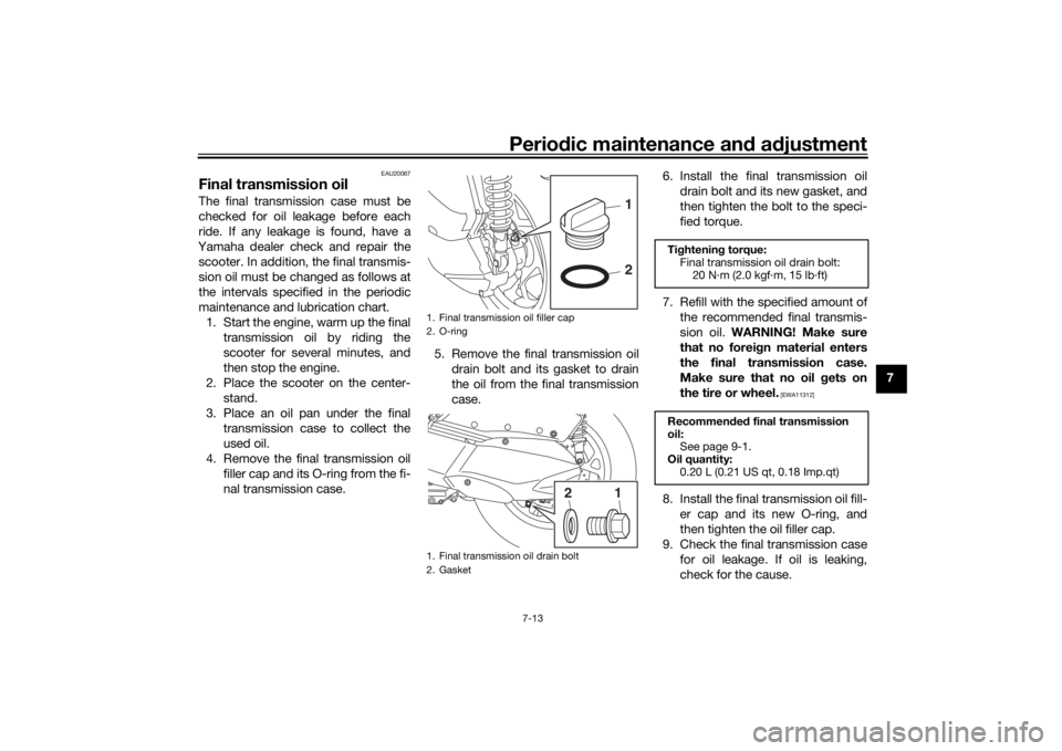
Final transmission oilThe final transmission case must be
checked for oil leakage before each
ride. If any leakage is found, have a
Yamaha dealer check and repair the scooter. In addition, the final transmis-
sion oil must be changed as follows at
the intervals specified in the periodic
maintenance and lubrication chart. 1. Start the engine, warm up the final transmission oil by riding the
scooter for several minutes, and
then stop the engine.
2. Place the scooter on the center- stand.
3. Place an oil pan under the final transmission case to collect the
used oil.
4. Remove the final transmission oil filler cap and its O-ring from the fi-
nal transmission case. 5. Remove the final transmission oil
drain bolt and its gasket to drain
the oil from the final transmission
case. 6. Install the final transmission oil
drain bolt and its new gasket, and
then tighten the bolt to the speci-
fied torque.
7. Refill with the specified amount of the recommended final transmis-
sion oil. WARNING! Make sure
that no forei gn material enters
the final transmission case.
Make sure that no oil gets on
the tire or wheel.
[EWA11312]
8. Install the final transmission oil fill- er cap and its new O-ring, and
then tighten the oil filler cap.
9. Check the final transmission case for oil leakage. If oil is leaking,
check for the cause.
1. Final transmission oil filler cap
2. O-ring
1. Final transmission oil drain bolt
2. Gasket
1
21
2
Tightenin g torque:
Final transmission oil drain bolt: 20 N·m (2.0 kgf·m, 15 lb·ft)
Recommen ded final transmission
oil: See page 9-1.
Oil quantity: 0.20 L (0.21 US qt, 0.18 Imp.qt)
UBBAE0E0.book Page 13 Thursday, September 24, 2020 3:19 PM
Page 84 of 114

Periodic maintenance an d a djustment
7-22
7
EAU21963
Cast wheelsTo maximize the performance, durabil-
ity, and safe operation of your vehicle,
note the following points regarding the
specified wheels.
The wheel rims should be
checked for cracks, bends, warp-
age or other damage before each
ride. If any damage is found, have
a Yamaha dealer replace the
wheel. Do not attempt even the
smallest repair to the wheel. A de-
formed or cracked wheel must be
replaced.
The wheel should be balanced
whenever either the tire or wheel
has been changed or replaced. An
unbalanced wheel can result in
poor performance, adverse han-
dling characteristics, and a short-
ened tire life.
EAU50861
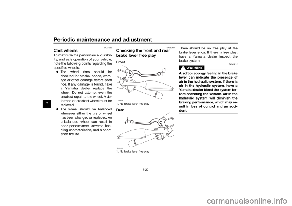
Checkin g the front an d rear
b rake lever free playFront
Rear There should be no free play at the
brake lever ends. If there is free play,
have a Yamaha dealer inspect the
brake system.
WARNING
EWA14212
A soft or spon
gy feelin g in the brake
lever can in dicate the presence of
air in the hy draulic system. If there is
air in the hy draulic system, have a
Yamaha dealer blee d the system b e-
fore operatin g the vehicle. Air in the
hy draulic system will d iminish the
b rakin g performance, which may re-
sult in loss of control an d an acci-
d ent.
1. No brake lever free play
1. No brake lever free playZAUM1049ZAUM1050
UBBAE0E0.book Page 22 Thursday, September 24, 2020 3:19 PM
Page 105 of 114

Specifications
9-1
9
Dimensions:Overall length:2185 mm (86.0 in)
Overall width:
775 mm (30.5 in)
Overall height: 1415/1465 mm (55.7/57.7 in)
Seat height: 795 mm (31.3 in)
Wheelbase:
1540 mm (60.6 in)
Ground clearance: 135 mm (5.31 in)
Minimum turning radius: 2.6 m (8.53 ft)Wei ght:Curb weight:
179 kg (395 lb)Engine:Combustion cycle:
4-stroke
Cooling system: Liquid cooled
Valve train: SOHC
Number of cylinders:
Single cylinder
Displacement: 292 cm³
Bore × stroke:
70.0 × 75.9 mm (2.76 × 2.99 in)
Starting system:
Electric starter
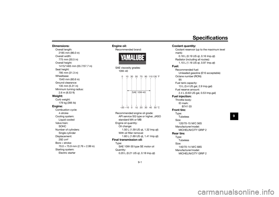
Engine oil:Recommended brand:
SAE viscosity grades:
10W-40
Recommended engine oil grade: API service SG type or higher, JASO
standard MA or MB
Engine oil quantity: Oil change:1.50 L (1.59 US qt, 1.32 Imp.qt)
With oil filter removal: 1.60 L (1.69 US qt, 1.41 Imp.qt)Final transmission oil:Type:SAE 10W-30 type SE motor oil
Quantity: 0.20 L (0.21 US qt, 0.18 Imp.qt)
Coolant quantity:Coolant reservoir (up to the maximum level
mark):0.18 L (0.19 US qt, 0.16 Imp.qt)
Radiator (including all routes): 1.10 L (1.16 US qt, 0.97 Imp.qt)Fuel:Recommended fuel:Unleaded gasoline (E10 acceptable)
Octane number (RON): 95
Fuel tank capacity:
13 L (3.4 US gal, 2.9 Imp.gal)
Fuel reserve amount: 2.4 L (0.63 US gal, 0.53 Imp.gal)Fuel injection:Throttle body:
ID mark:B741 03Front tire:Type: Tubeless
Size: 120/70-15 M/C 56S
Manufacturer/model:
MICHELIN/CITY GRIP 2Rear tire:Type:Tubeless
Size:
140/70-14 M/C 68S
Manufacturer/model: MICHELIN/CITY GRIP 2
–20 –10 0 1020 30 40 50 �C
10 30 50 70 90 110
0 130 �F
SAE 10W-40
UBBAE0E0.book Page 1 Thursday, September 24, 2020 3:19 PM