change time YAMAHA XMAX 400 2020 Owners Manual
[x] Cancel search | Manufacturer: YAMAHA, Model Year: 2020, Model line: XMAX 400, Model: YAMAHA XMAX 400 2020Pages: 118, PDF Size: 9.04 MB
Page 31 of 118

Instrument and control functions
4-5
4 When approximately 2.4 L (0.63
US gal, 0.53 Imp.gal) of fuel re-
mains in the fuel tank, the last seg-
ment of the fuel meter will start
flashing. The display will automat-
ically change to the fuel reserve
tripmeter “F Trip” and start count-
ing the distance traveled from that
point.
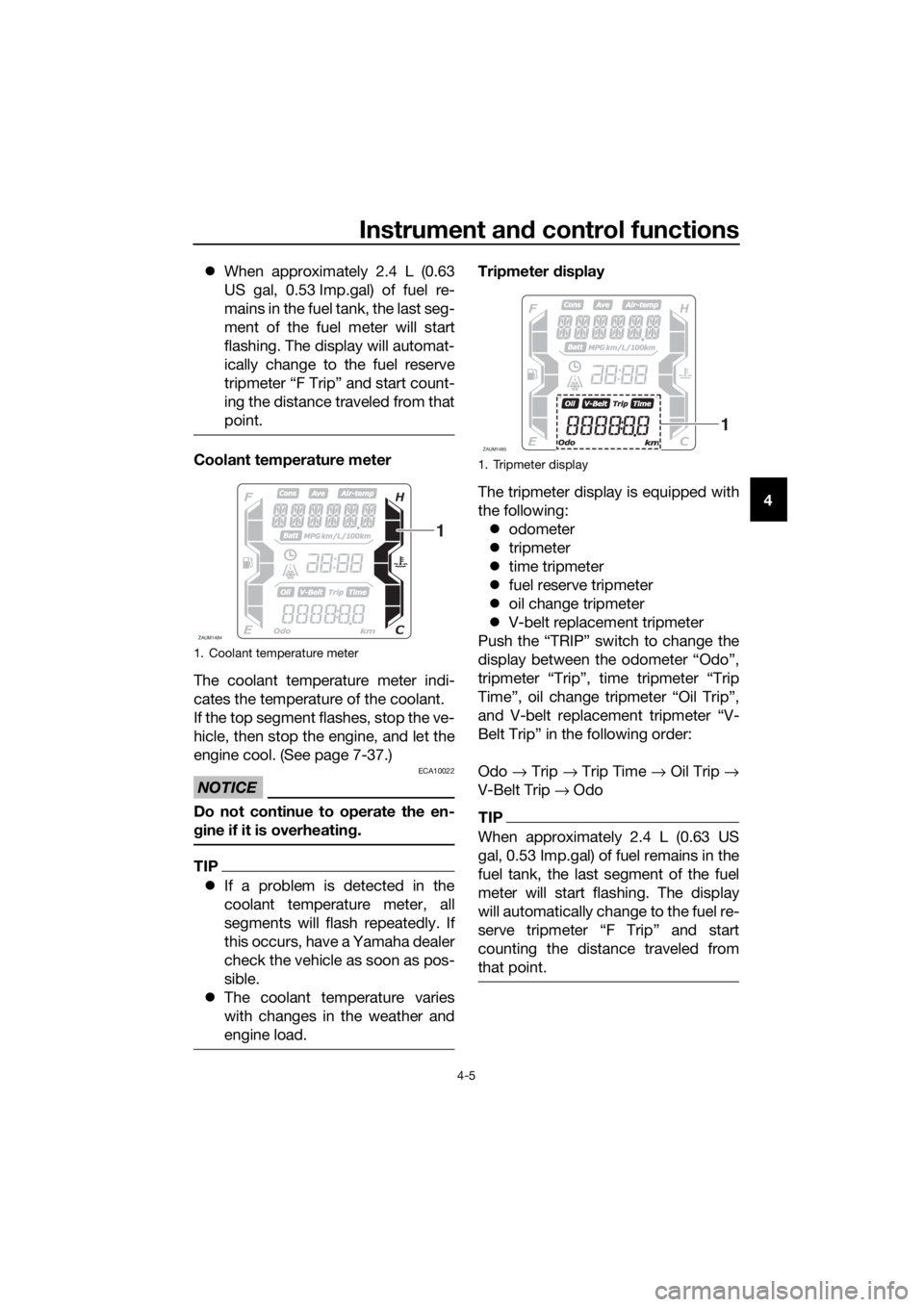
Coolant temperature meter
The coolant temperature meter indi-
cates the temperature of the coolant.
If the top segment flashes, stop the ve-
hicle, then stop the engine, and let the
engine cool. (See page 7-37.)
NOTICE
ECA10022
Do not continue to operate the en-
gine if it is overheating.
TIP
If a problem is detected in the
coolant temperature meter, all
segments will flash repeatedly. If
this occurs, have a Yamaha dealer
check the vehicle as soon as pos-
sible.
The coolant temperature varies
with changes in the weather and
engine load.
Tripmeter display
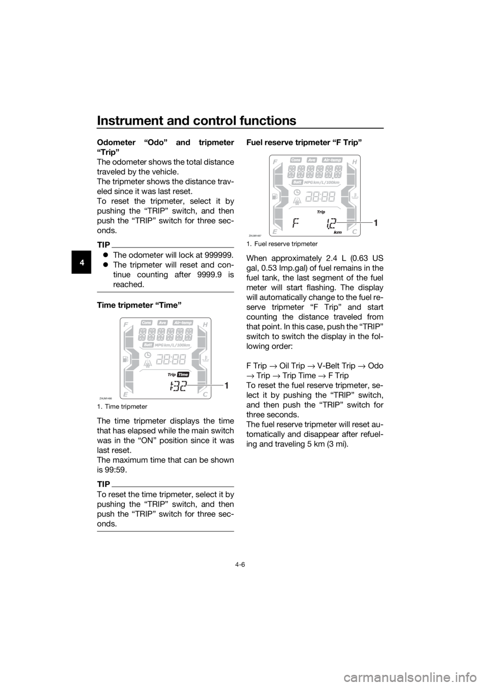
The tripmeter display is equipped with
the following:
odometer
tripmeter
time tripmeter
fuel reserve tripmeter
oil change tripmeter
V-belt replacement tripmeter
Push the “TRIP” switch to change the
display between the odometer “Odo”,
tripmeter “Trip”, time tripmeter “Trip
Time”, oil change tripmeter “Oil Trip”,
and V-belt replacement tripmeter “V-
Belt Trip” in the following order:
Odo → Trip → Trip Time → Oil Trip →
V-Belt Trip → Odo
TIP
When approximately 2.4 L (0.63 US
gal, 0.53 Imp.gal) of fuel remains in the
fuel tank, the last segment of the fuel
meter will start flashing. The display
will automatically change to the fuel re-
counting the distance traveled from
that point.
1. Coolant temperature meter
ZAUM1484
1
1. Tripmeter display
ZAUM1485
1
UBL1E0E0.book Page 5 Thursday, May 11, 2017 8:51 AM
Page 32 of 118

Instrument and control functions
4-6
4Odometer “Odo” and tripmeter
“Trip”
The odometer shows the total distance
traveled by the vehicle.
The tripmeter shows the distance trav-
eled since it was last reset.
To reset the tripmeter, select it by
pushing the “TRIP” switch, and then
push the “TRIP” switch for three sec-
onds.
TIP
The odometer will lock at 999999.
The tripmeter will reset and con-
tinue counting after 9999.9 is
reached.
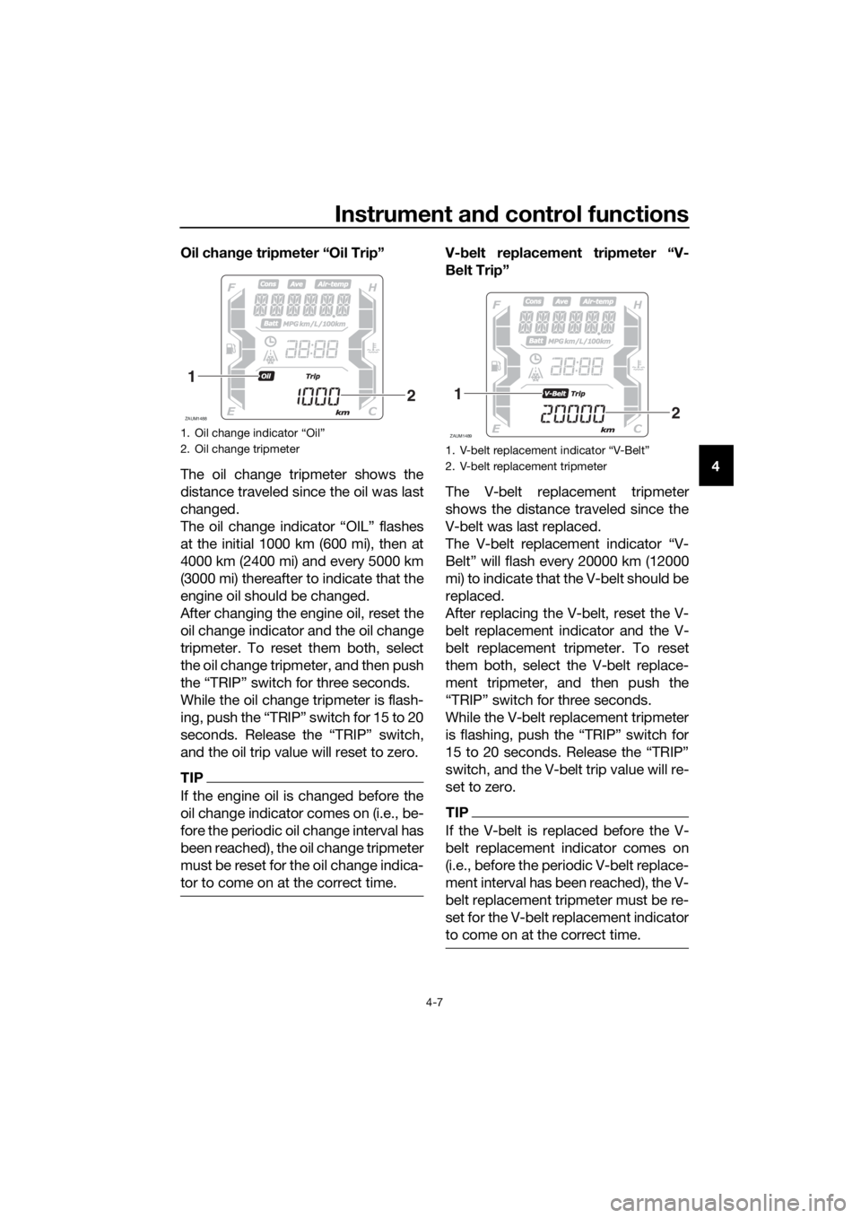
Time tripmeter “Time”
The time tripmeter displays the time
that has elapsed while the main switch
was in the “ON” position since it was
last reset.
The maximum time that can be shown
is 99:59.
TIP
To reset the time tripmeter, select it by
onds.
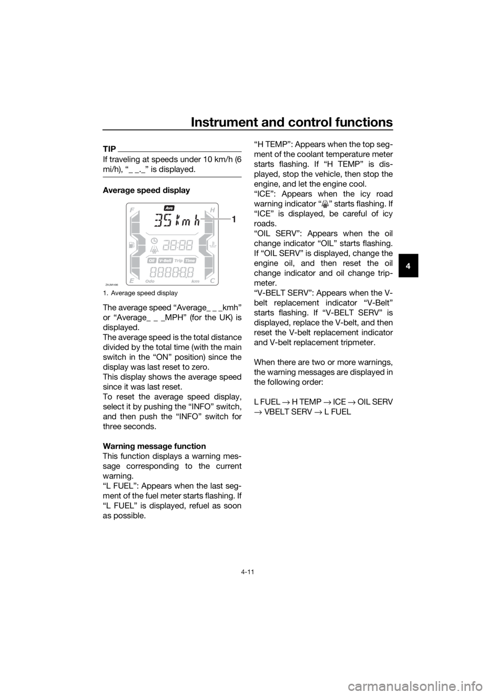
Fuel reserve tripmeter “F Trip”
When approximately 2.4 L (0.63 US
gal, 0.53 Imp.gal) of fuel remains in the
fuel tank, the last segment of the fuel
meter will start flashing. The display
will automatically change to the fuel re-
serve tripmeter “F Trip” and start
counting the distance traveled from
that point. In this case, push the “TRIP”
switch to switch the display in the fol-
lowing order:
F Trip → Oil Trip → V-Belt Trip → Odo
→ Trip → Trip Time → F Trip
To reset the fuel reserve tripmeter, se-
lect it by pushing the “TRIP” switch,
and then push the “TRIP” switch for
three seconds.
The fuel reserve tripmeter will reset au-
tomatically and disappear after refuel-
ing and traveling 5 km (3 mi).
1. Time tripmeter
ZAUM1486
1
1. Fuel reserve tripmeter
ZAUM1487
1
UBL1E0E0.book Page 6 Thursday, May 11, 2017 8:51 AM
Page 33 of 118

Instrument and control functions
4-7
4 Oil change tripmeter “Oil Trip”
The oil change tripmeter shows the
distance traveled since the oil was last
changed.
The oil change indicator “OIL” flashes
at the initial 1000 km (600 mi), then at
4000 km (2400 mi) and every 5000 km
(3000 mi) thereafter to indicate that the
engine oil should be changed.
After changing the engine oil, reset the
oil change indicator and the oil change
tripmeter. To reset them both, select
the oil change tripmeter, and then push
the “TRIP” switch for three seconds.
While the oil change tripmeter is flash-
ing, push the “TRIP” switch for 15 to 20
seconds. Release the “TRIP” switch,
and the oil trip value will reset to zero.
TIP
If the engine oil is changed before the
oil change indicator comes on (i.e., be-
fore the periodic oil change interval has
been reached), the oil change tripmeter
must be reset for the oil change indica-
tor to come on at the correct time.
V-belt replacement tripmeter “V-
Belt Trip”
The V-belt replacement tripmeter
shows the distance traveled since the
V-belt was last replaced.
The V-belt replacement indicator “V-
Belt” will flash every 20000 km (12000
mi) to indicate that the V-belt should be
replaced.
After replacing the V-belt, reset the V-
belt replacement indicator and the V-
belt replacement tripmeter. To reset
them both, select the V-belt replace-
ment tripmeter, and then push the
“TRIP” switch for three seconds.
While the V-belt replacement tripmeter
is flashing, push the “TRIP” switch for
15 to 20 seconds. Release the “TRIP”
switch, and the V-belt trip value will re-
set to zero.
TIP
If the V-belt is replaced before the V-
belt replacement indicator comes on
(i.e., before the periodic V-belt replace-
ment interval has been reached), the V-
belt replacement tripmeter must be re-
set for the V-belt replacement indicator
to come on at the correct time.
1.
2. Oil change tripmeter
ZAUM1488
1
2
1.
2. V-belt replacement tripmeter
ZAUM1489
1
2
UBL1E0E0.book Page 7 Thursday, May 11, 2017 8:51 AM
Page 37 of 118

Instrument and control functions
4-11
4
TIP
If traveling at speeds under 10 km/h (6
mi/h), “_ _._” is displayed.
Average speed display
The average speed “Average_ _ _kmh”
or “Average_ _ _MPH” (for the UK) is
displayed.
The average speed is the total distance
divided by the total time (with the main
switch in the “ON” position) since the
display was last reset to zero.
This display shows the average speed
since it was last reset.
To reset the average speed display,
select it by pushing the “INFO” switch,
and then push the “INFO” switch for
three seconds.
Warning message function
This function displays a warning mes-
sage corresponding to the current
warning.
“L FUEL”: Appears when the last seg-
ment of the fuel meter starts flashing. If
“L FUEL” is displayed, refuel as soon
as possible.“H TEMP”: Appears when the top seg-
ment of the coolant temperature meter
starts flashing. If “H TEMP” is dis-
played, stop the vehicle, then stop the
engine, and let the engine cool.
“ICE”: Appears when the icy road
warning indicator “ ” starts flashing. If
“ICE” is displayed, be careful of icy
roads.
“OIL SERV”: Appears when the oil
change indicator “OIL” starts flashing.
If “OIL SERV” is displayed, change the
engine oil, and then reset the oil
change indicator and oil change trip-
meter.
“V-BELT SERV”: Appears when the V-
belt replacement indicator “V-Belt”
starts flashing. If “V-BELT SERV” is
displayed, replace the V-belt, and then
reset the V-belt replacement indicator
and V-belt replacement tripmeter.
When there are two or more warnings,
the warning messages are displayed in
the following order:
L FUEL → H TEMP → ICE → OIL SERV
→ VBELT SERV → L FUEL
1. Average speed display
ZAUM1496
1
UBL1E0E0.book Page 11 Thursday, May 11, 2017 8:51 AM
Page 38 of 118

Instrument and control functions
4-12
4
EAU1234M
Handlebar switches
Left
Right
EAU54201Dimmer/Pass switch “ / /PASS”
Set this switch to “ ” for the high
beam and to “ ” for the low beam.
To flash the high beam, push the pass
side “PASS” of the switch while the
headlights are on low beam.
EAU12461Turn signal switch “ / ”
To signal a right-hand turn, push this
switch to “ ”. To signal a left-hand
turn, push this switch to “ ”. When
released, the switch returns to the cen-ter position. To cancel the turn signal
lights, push the switch in after it has re-
turned to the center position.
EAU12501Horn switch “ ”
Press this switch to sound the horn.
EAU54212Stop/Run/Start switch “ / / ”
To crank the engine with the starter,
set this switch to “ ”, and then push
the switch down towards “ ”. See
page 6-2 for starting instructions prior
to starting the engine.
Set this switch to “ ” to stop the en-
gine in case of an emergency, such as
when the vehicle overturns or when the
throttle cable is stuck.
EAU78190Hazard switch “ ”
With the main switch in the “ON”
or “ ” position, use this switch to turn
on the hazard lights (simultaneous
flashing of all turn signal lights).
The hazard lights are used in case of an
emergency or to warn other drivers
when your vehicle is stopped where it
might be a traffic hazard.
NOTICE
ECA10062
Do not use the hazard lights for an
extended length of time with the en-
gine not running, otherwise the bat-
tery may discharge.
EAU78491“TRIP/INFO” switch
This switch is used to make setting and
display changes in the multi-function
meter unit. See page 4-3 for more in-
formation.
1. Dimmer/Pass switch “ / /PASS”
2. Turn signal switch “ / ”
3. Horn switch “ ”
1. Stop/Run/Start switch “ / / ”
2. Hazard switch “ ”
3. “TRIP/INFO” switch
1
2
3
1
2
3
UBL1E0E0.book Page 12 Thursday, May 11, 2017 8:51 AM
Page 43 of 118

Instrument and control functions
4-17
4 When the vehicle is turned on, traction
control is automatically turned on.
To turn the traction control system off,
use the “INFO” switch to change the
information display to the traction con-
trol system display. Then push the “IN-
FO” switch for three seconds. The
display will show “TCSOFF” , and the
“TCS” indicator light will come on.
TIP
Turn the traction control system off to
help free the rear wheel if the vehicle
gets stuck in mud, sand, or other soft
surfaces.
NOTICE
ECA16801
Use only the specified tires. (See
page 7-18.) Using different sized
tires will prevent the traction control
system from controlling tire rotation
accurately.
Resetting the traction control sys-
tem
The traction control system will auto-
matically disable under certain condi-
tions; such as when a sensor fault is
detected, or when only one wheel is al-
lowed to rotate for more than a fewseconds. Should this happen, the “ ”
indicator light will come on, and possi-
bly the “ ” warning light, too.
TIP
When the vehicle is on the centerstand,
do not rev the engine for an extended
period of time. Otherwise, the traction
control system will automatically dis-
able and need to be reset.
If the traction control system automat-
ically disables, try resetting it as fol-
lows.
1. Stop the vehicle and turn it off
completely.
2. Wait a few seconds and then turn
the vehicle power on.
3. The Ž indicator light should
turn off and the system be en-
abled.
TIP
If the Ž indicator light remains on af-
ter resetting, the vehicle may still be
ridden; however, have a Yamaha deal-
er check the vehicle as soon as possi-
ble.
4. Have a Yamaha dealer check the
vehicle and turn off the Ž
warning light.
1. Traction control system indicator light Ž
2. Traction control system display
ZAUM1499
12
1. Traction control system indicator light Ž
2. Engine trouble warning light Ž
ZAUM1500
UBL1E0E0.book Page 17 Thursday, May 11, 2017 8:51 AM
Page 76 of 118

Periodic maintenance and adjustment
7-12
710. Start the engine, and then let it idle
for several minutes while checking
it for oil leakage. If oil is leaking,
immediately turn the engine off
and check for the cause.
11. Reset the oil change indicator.
(See page 4-7.)
TIP
If the engine oil is changed before the
oil change indicator comes on (i.e. be-
fore the periodic oil change interval has
been reached), the indicator must be
reset after the oil change for the next
periodic oil change to be indicated at
the correct time.
EAU20067
Final transmission oil
The final transmission case must be
checked for oil leakage before each
ride. If any leakage is found, have a
Yamaha dealer check and repair the
scooter. In addition, the final transmis-
sion oil must be changed as follows at
the intervals specified in the periodic
maintenance and lubrication chart.
1. Start the engine, warm up the final
transmission oil by riding the
scooter for several minutes, and
then stop the engine.
2. Place the scooter on the center-
stand.
3. Place an oil pan under the final
transmission case to collect the
used oil.
4. Remove the final transmission oil
filler cap and its O-ring from the fi-
nal transmission case.
5. Remove the final transmission oil
drain bolt and its gasket to drain
the oil from the final transmission
case.
1. Final transmission oil filler cap
2. O-ring
3. Final transmission oil drain bolt
4. Gasket
2
1
3
4
UBL1E0E0.book Page 12 Thursday, May 11, 2017 8:51 AM
Page 82 of 118

Periodic maintenance and adjustment
7-18
7
EAU21402
Valve clearance
The valve clearance changes with use,
resulting in improper air-fuel mixture
and/or engine noise. To prevent this
from occurring, the valve clearance
must be adjusted by a Yamaha dealer
at the intervals specified in the periodic
maintenance and lubrication chart.
EAU69760
Tires
Tires are the only contact between the
vehicle and the road. Safety in all con-
ditions of riding depends on a relatively
small area of road contact. Therefore, it
is essential to maintain the tires in good
condition at all times and replace them
at the appropriate time with the speci-
fied tires.
Tire air pressure
The tire air pressure should be
checked and, if necessary, adjusted
before each ride.
WARNING
EWA10504
Operation of this vehicle with im-
proper tire pressure may cause se-
vere injury or death from loss of
control.
The tire air pressure must be
checked and adjusted on cold
tires (i.e., when the temperature
of the tires equals the ambient
temperature).
The tire air pressure must be
adjusted in accordance with the
riding speed and with the total
weight of rider, passenger, car-
go, and accessories approved
for this model.
UBL1E0E0.book Page 18 Thursday, May 11, 2017 8:51 AM