clock YAMAHA XSR 700 2018 Owners Manual
[x] Cancel search | Manufacturer: YAMAHA, Model Year: 2018, Model line: XSR 700, Model: YAMAHA XSR 700 2018Pages: 98, PDF Size: 7.36 MB
Page 21 of 98
Instrument and control functions
3-6
3 2. Use the code re-registering key to
start the engine.
3. If the engine starts, turn it off, and
try starting the engine with the
standard keys.
4. If one or both of the standard keys
do not start the engine, take the
vehicle and all 3 keys to a Yamaha
dealer to have the standard keys
re-registered.
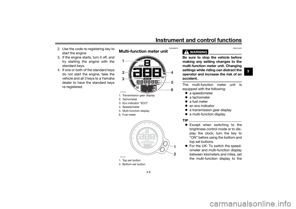
EAUM3610
Multi-function meter unit
WARNING
EWA12423
Be sure to stop the vehicle before
making any setting changes to the
multi-function meter unit. Changing
settings while riding can distract the
operator and increase the risk of an
accident.The multi-function meter unit is
equipped with the following:
a speedometer
a tachometer
a fuel meter
an eco indicator
a transmission gear display
a multi-function displayTIPExcept when switching to the
brightness control mode or to dis-
play the clock, turn the key to
“ON” before using the bottom and
top set buttons.
For the UK: To switch the speed-
ometer and multi-function display
between kilometers and miles, set
the multi-function display to the
1. Transmission gear display
2. Tachometer
3. Eco indicator “ECO”
4. Speedometer
5. Multi-function display
6. Fuel meter
1. Top set button
2. Bottom set buttonZAUM113281
2
34
5
6ZAUM1329
1
2
UBU3E1E0.book Page 6 Monday, June 4, 2018 5:20 PM
Page 23 of 98
Instrument and control functions
3-8
3 Select the transmission gear that
is appropriate for the vehicle
speed.
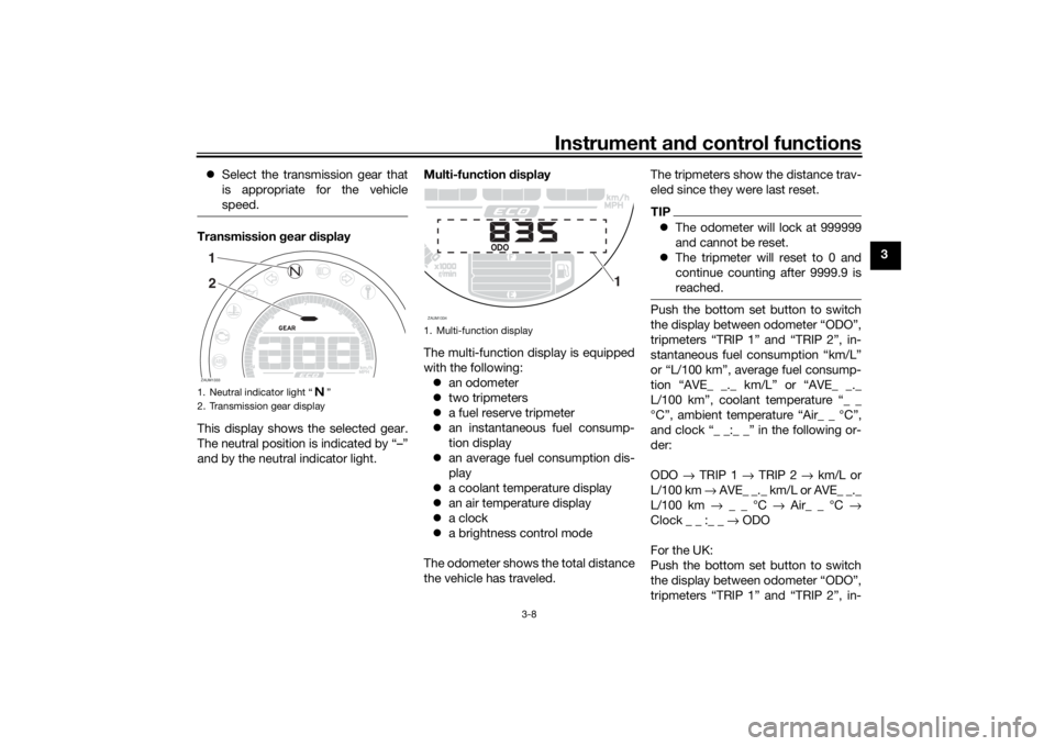
Transmission gear display
This display shows the selected gear.
The neutral position is indicated by “–”
and by the neutral indicator light.Multi-function display
The multi-function display is equipped
with the following:
an odometer
two tripmeters
a fuel reserve tripmeter
an instantaneous fuel consump-
tion display
an average fuel consumption dis-
play
a coolant temperature display
an air temperature display
a clock
a brightness control mode
The odometer shows the total distance
the vehicle has traveled.The tripmeters show the distance trav-
eled since they were last reset.
TIPThe odometer will lock at 999999
and cannot be reset.
The tripmeter will reset to 0 and
continue counting after 9999.9 is
reached.Push the bottom set button to switch
the display between odometer “ODO”,
tripmeters “TRIP 1” and “TRIP 2”, in-
stantaneous fuel consumption “km/L”
or “L/100 km”, average fuel consump-
tion “AVE_ _._ km/L” or “AVE_ _._
L/100 km”, coolant temperature “_ _
°C”, ambient temperature “Air_ _ °C”,
and clock “_ _:_ _” in the following or-
der:
ODO → TRIP 1 → TRIP 2 → km/L or
L/100 km → AVE_ _._ km/L or AVE_ _._
L/100 km → _ _ °C → Air_ _ °C →
Clock _ _ :_ _ → ODO
For the UK:
Push the bottom set button to switch
the display between odometer “ODO”,
tripmeters “TRIP 1” and “TRIP 2”, in-
1. Neutral indicator light “ ”
2. Transmission gear displayZAUM133312
1. Multi-function displayZAUM1334
1
UBU3E1E0.book Page 8 Monday, June 4, 2018 5:20 PM
Page 24 of 98
Instrument and control functions
3-9
3stantaneous fuel consumption “km/L”,
“L/100 km” or “MPG”, average fuel
consumption “AVE_ _._ km/L”, “AVE_
_._ L/100 km” or “AVE_ _._ MPG”,
coolant temperature “_ _ °C”, and am-
bient temperature, and “Air_ _ °C”, and
clock “_ _:_ _” in the following order:
ODO → TRIP 1 → TRIP 2 → km/L,
L/100 km or MPG → AVE_ _._ km/L,
AVE_ _._ L/100 km or AVE_ _._ MPG →
_ _ °C → Air_ _ °C → Clock _ _ :_ _ →
ODO
TIPPush the top set button to switch
the display in the reverse order.
The fuel reserve tripmeter and er-
ror code displays come on auto-
matically, while the brightness
control mode is accessed sepa-
rately.If the lower segment and frame of the
fuel meter start flashing, the display
automatically changes to fuel reserve
tripmeter “TRIP F” and starts counting
the distance traveled from that point. In
this case, push the bottom set buttonto switch the display between the vari-
ous tripmeter, odometer, and fuel con-
sumption modes in the following order:
TRIP F → km/L or L/100 km → AVE_
_._ km/L or AVE_ _._ L/100 km → _ _
°C → Air_ _ °C → Clock _ _ :_ _ → ODO
→ TRIP 1 → TRIP 2 → TRIP F
For the UK :
TRIP F → km/L, L/100 km or MPG →
AVE_ _._ km/L, AVE_ _._ L/100 km or
AVE_ _._ MPG → _ _ °C → Air_ _ °C →
Clock _ _ :_ _ → ODO → TRIP 1 →
TRIP 2 → TRIP F
To reset a tripmeter, select it by push-
ing the bottom set button, and then
push the top set button for one sec-
ond.
If you do not reset the fuel reserve trip-
meter manually, after refueling and
traveling 5km (3mi) it resets automati-
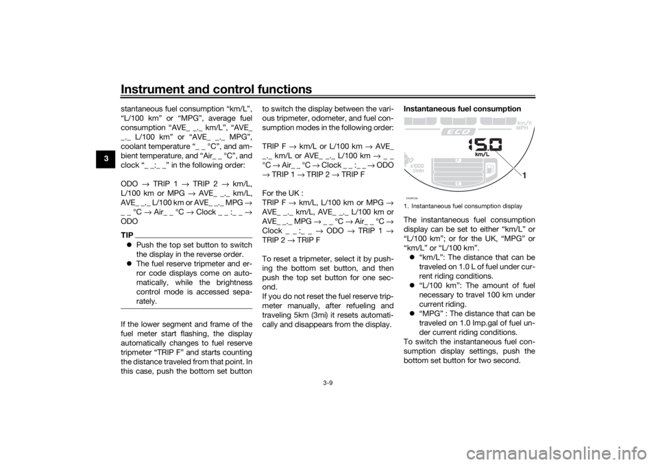
cally and disappears from the display.Instantaneous fuel consumption
The instantaneous fuel consumption
display can be set to either “km/L” or
“L/100 km”; or for the UK, “MPG” or
“km/L” or “L/100 km”.
“km/L”: The distance that can be
traveled on 1.0 L of fuel under cur-
rent riding conditions.
“L/100 km”: The amount of fuel
necessary to travel 100 km under
current riding.
“MPG” : The distance that can be
traveled on 1.0 Imp.gal of fuel un-
der current riding conditions.
To switch the instantaneous fuel con-
sumption display settings, push the
bottom set button for two second.
1. Instantaneous fuel consumption displayZAUM1335
1
UBU3E1E0.book Page 9 Monday, June 4, 2018 5:20 PM
Page 26 of 98
Instrument and control functions
3-11
3This display shows the air temperature
from –9 °C to 99 °C in 1 °C increments.
The temperature displayed may vary
from the actual ambient temperature.
TIPWhen the air temperature is below
–9 °C, “Lo” will be displayed.
The accuracy of the temperature
reading may be affected when rid-
ing slowly (under 20 km/h [12.5
mi/h]) or when stopped at traffic
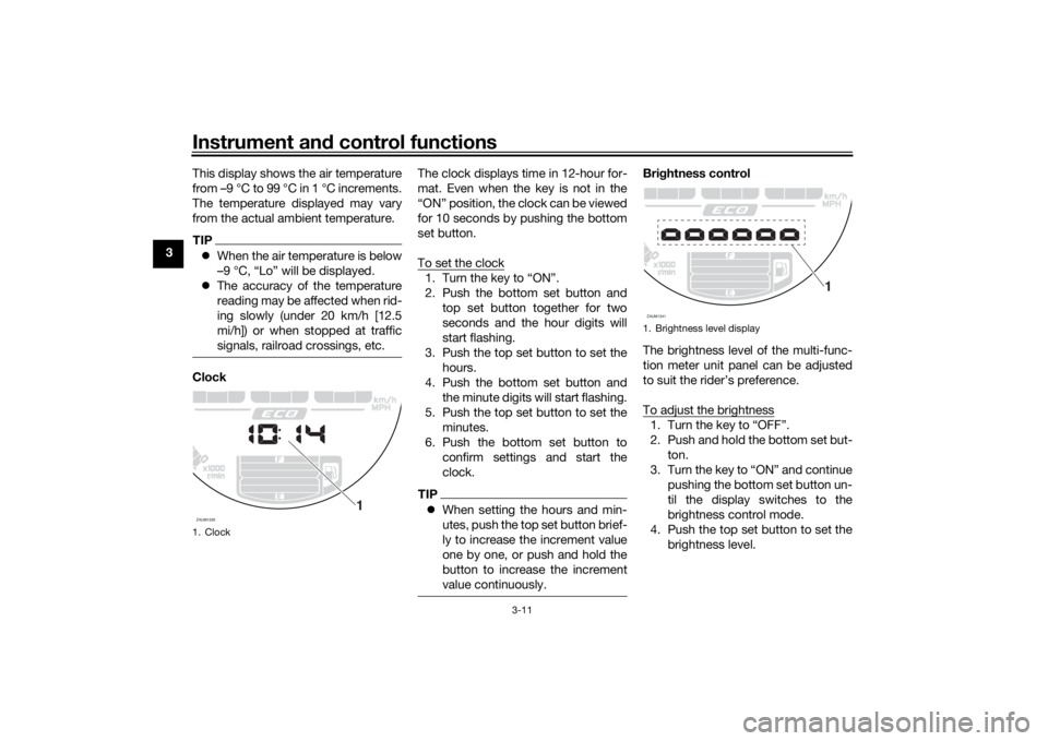
signals, railroad crossings, etc.ClockThe clock displays time in 12-hour for-
mat. Even when the key is not in the
“ON” position, the clock can be viewed
for 10 seconds by pushing the bottom
set button.
To set the clock
1. Turn the key to “ON”.
2. Push the bottom set button and
top set button together for two
seconds and the hour digits will
start flashing.
3. Push the top set button to set the
hours.
4. Push the bottom set button and
the minute digits will start flashing.
5. Push the top set button to set the
minutes.
6. Push the bottom set button to
confirm settings and start the
clock.TIPWhen setting the hours and min-
utes, push the top set button brief-
ly to increase the increment value
one by one, or push and hold the
button to increase the increment
value continuously.
Brightness control
The brightness level of the multi-func-
tion meter unit panel can be adjusted
to suit the rider’s preference.
To adjust the brightness1. Turn the key to “OFF”.
2. Push and hold the bottom set but-
ton.
3. Turn the key to “ON” and continue
pushing the bottom set button un-
til the display switches to the
brightness control mode.
4. Push the top set button to set the
brightness level.
1. ClockZAUM1339
1
1. Brightness level displayZAUM1341
1
UBU3E1E0.book Page 11 Monday, June 4, 2018 5:20 PM
Page 30 of 98
Instrument and control functions
3-15
3
TIPThe ABS performs a self-diagno-
sis test each time the vehicle first
starts off after the key is turned to
“ON” and the vehicle has traveled
at a speed of 10 km/h (6 mi/h) or
higher. During this test, a “click-
ing” noise can be heard from the
hydraulic control unit, and if the
brake lever or brake pedal is even
slightly applied, a vibration can be
felt at the lever and pedal, but
these do not indicate a malfunc-
tion.
This ABS has a test mode which
allows the owner to experience
the pulsation at the brake lever or
brake pedal when the ABS is op-
erating. However, special tools are
required, so please consult your
Yamaha dealer.NOTICE
ECA20100
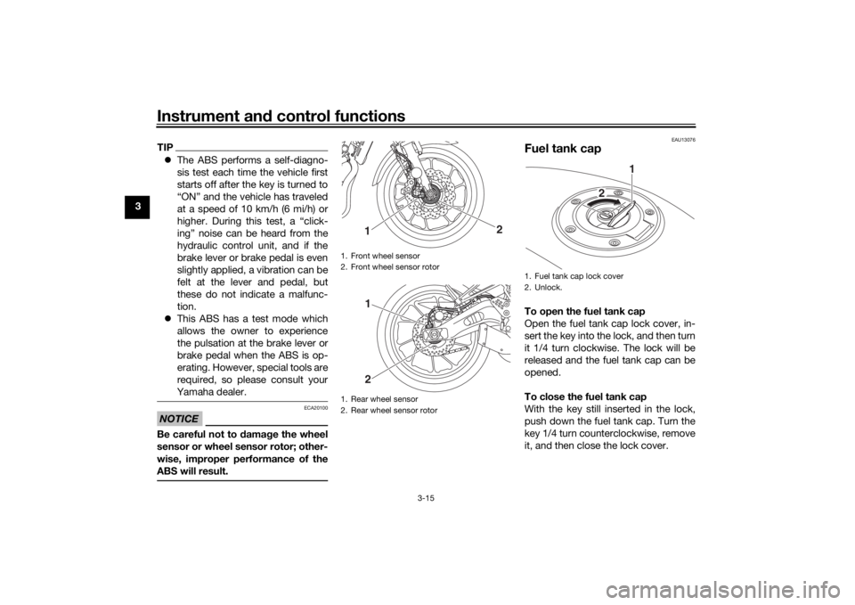
Be careful not to damage the wheel
sensor or wheel sensor rotor; other-
wise, improper performance of the
ABS will result.
EAU13076
Fuel tank capTo open the fuel tank cap
Open the fuel tank cap lock cover, in-
sert the key into the lock, and then turn
it 1/4 turn clockwise. The lock will be
released and the fuel tank cap can be
opened.
To close the fuel tank cap
With the key still inserted in the lock,
push down the fuel tank cap. Turn the
key 1/4 turn counterclockwise, remove
it, and then close the lock cover.
1. Front wheel sensor
2. Front wheel sensor rotor
1. Rear wheel sensor
2. Rear wheel sensor rotor
1
2
12
1. Fuel tank cap lock cover
2. Unlock.
1
2
UBU3E1E0.book Page 15 Monday, June 4, 2018 5:20 PM
Page 34 of 98
Instrument and control functions
3-19
3
EAU83140
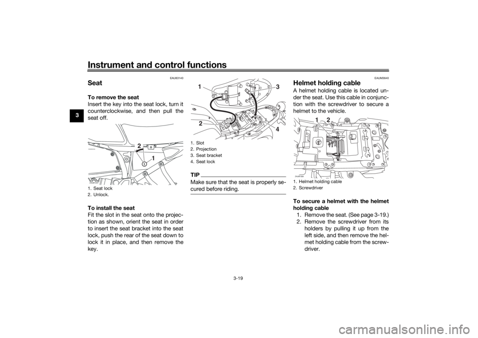
SeatTo remove the seat
Insert the key into the seat lock, turn it
counterclockwise, and then pull the
seat off.
To install the seat
Fit the slot in the seat onto the projec-
tion as shown, orient the seat in order
to insert the seat bracket into the seat
lock, push the rear of the seat down to
lock it in place, and then remove the
key.
TIPMake sure that the seat is properly se-
cured before riding.
EAUM3640
Helmet holding cableA helmet holding cable is located un-
der the seat. Use this cable in conjunc-
tion with the screwdriver to secure a
helmet to the vehicle.
To secure a helmet with the helmet
holding cable
1. Remove the seat. (See page 3-19.)
2. Remove the screwdriver from its
holders by pulling it up from the
left side, and then remove the hel-
met holding cable from the screw-
driver.
1. Seat lock
2. Unlock.ZAUM1344
2
1
1. Slot
2. Projection
3. Seat bracket
4. Seat lock
1
3
4
2
1. Helmet holding cable
2. ScrewdriverZAUM1359
12
UBU3E1E0.book Page 19 Monday, June 4, 2018 5:20 PM
Page 79 of 98
Periodic maintenance and adjustment
6-32
6
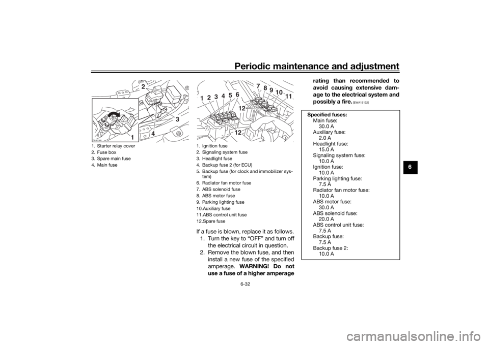
If a fuse is blown, replace it as follows.
1. Turn the key to “OFF” and turn off
the electrical circuit in question.
2. Remove the blown fuse, and then
install a new fuse of the specified
amperage. WARNING! Do not
use a fuse of a higher amperagerating than recommended to
avoid causing extensive dam-
age to the electrical system and
possibly a fire.
[EWA15132]
1. Starter relay cover
2. Fuse box
3. Spare main fuse
4. Main fuseZAUM1380
2
3
4
1
1. Ignition fuse
2. Signaling system fuse
3. Headlight fuse
4. Backup fuse 2 (for ECU)
5. Backup fuse (for clock and immobilizer sys-
tem)
6. Radiator fan motor fuse
7. ABS solenoid fuse
8. ABS motor fuse
9. Parking lighting fuse
10.Auxiliary fuse
11.ABS control unit fuse
12.Spare fuse
7
8
9
10
11
1
2
3
4
5
61212
Specified fuses:
Main fuse:
30.0 A
Auxiliary fuse:
2.0 A
Headlight fuse:
15.0 A
Signaling system fuse:
10.0 A
Ignition fuse:
10.0 A
Parking lighting fuse:
7.5 A
Radiator fan motor fuse:
10.0 A
ABS motor fuse:
30.0 A
ABS solenoid fuse:
20.0 A
ABS control unit fuse:
7.5 A
Backup fuse:
7.5 A
Backup fuse 2:
10.0 A
UBU3E1E0.book Page 32 Monday, June 4, 2018 5:20 PM
Page 82 of 98
Periodic maintenance and adjustment
6-35
64. Insert a new bulb into the socket.
5. Install the socket (together with
the bulb) by pushing it in.
6. Install the headlight unit.
EAU24182
Tail/brake lightThis model is equipped with an LED-
type tail/brake light.
If the tail/brake light does not come on,
have a Yamaha dealer check it.
EAU24205
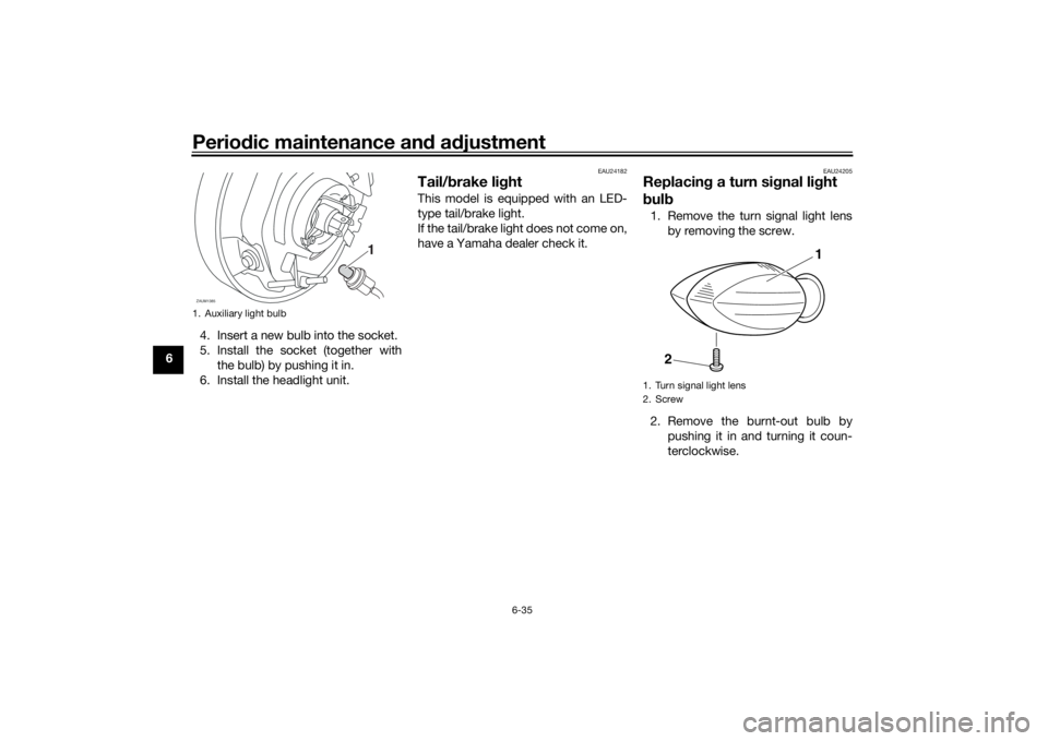
Replacing a turn signal light
bulb1. Remove the turn signal light lens
by removing the screw.
2. Remove the burnt-out bulb by
pushing it in and turning it coun-
terclockwise.
1. Auxiliary light bulbZAUM1385
1
1. Turn signal light lens
2. Screw
1
2
UBU3E1E0.book Page 35 Monday, June 4, 2018 5:20 PM
Page 83 of 98
Periodic maintenance and adjustment
6-36
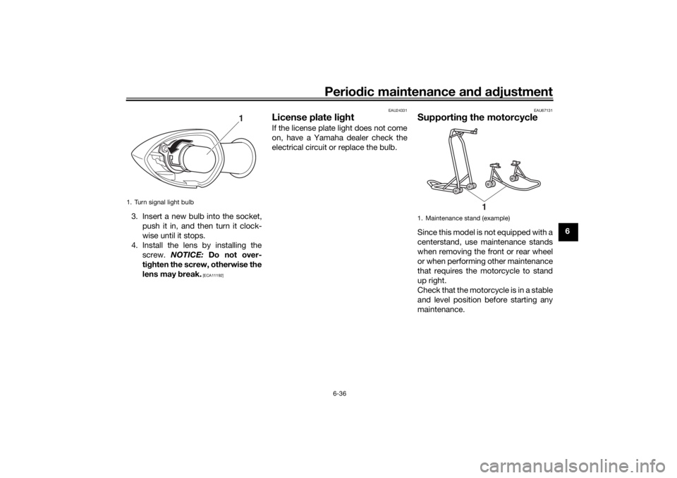
6 3. Insert a new bulb into the socket,
push it in, and then turn it clock-
wise until it stops.
4. Install the lens by installing the
screw. NOTICE: Do not over-
tighten the screw, otherwise the
lens may break.
[ECA11192]EAU24331
License plate lightIf the license plate light does not come
on, have a Yamaha dealer check the
electrical circuit or replace the bulb.
EAU67131
Supporting the motorcycleSince this model is not equipped with a
centerstand, use maintenance stands
when removing the front or rear wheel
or when performing other maintenance
that requires the motorcycle to stand
up right.
Check that the motorcycle is in a stable
and level position before starting any
maintenance.
1. Turn signal light bulb
1
1. Maintenance stand (example)
1
UBU3E1E0.book Page 36 Monday, June 4, 2018 5:20 PM
Page 86 of 98
Periodic maintenance and adjustment
6-39
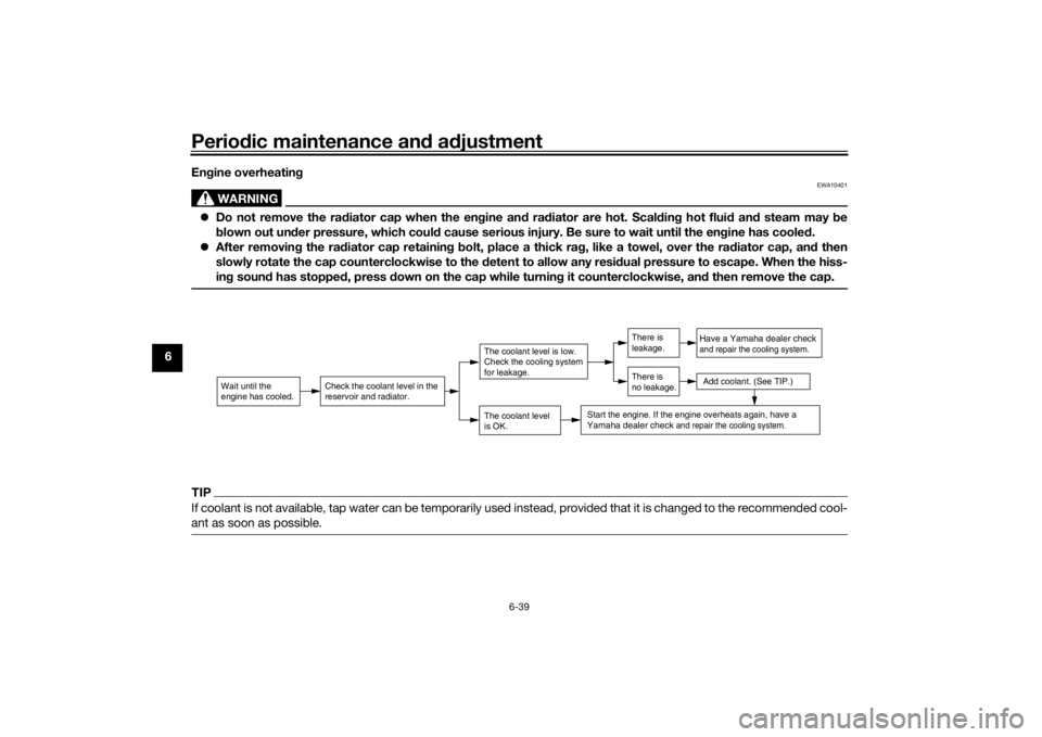
6Engine overheating
WARNING
EWA10401
Do not remove the radiator cap when the engine and radiator are hot. Scalding hot fluid and steam may be
blown out under pressure, which could cause serious injury. Be sure to wait until the engine has cooled.
After removing the radiator cap retaining bolt, place a thick rag, like a towel, over the radiator cap, and then
slowly rotate the cap counterclockwise to the detent to allow any residual pressure to escape. When the hiss-
ing sound has stopped, press down on the cap while turning it counterclockwise, and then remove the cap.TIPIf coolant is not available, tap water can be temporarily used instead, provided that it is changed to the recommended cool-
ant as soon as possible.
Wait until the
engine has cooled.
Check the coolant level in the
reservoir and radiator.
The coolant level
is OK.The coolant level is low.
Check the cooling system
for leakage.
Have a Yamaha dealer checkand repair the cooling system.Add coolant. (See TIP.)
Start the engine. If the engine overheats again,
have a
Yamaha dealer check
and repair the cooling system.
There is
leakage.
There is
no leakage.
UBU3E1E0.book Page 39 Monday, June 4, 2018 5:20 PM