oil YAMAHA XSR 700 2021 User Guide
[x] Cancel search | Manufacturer: YAMAHA, Model Year: 2021, Model line: XSR 700, Model: YAMAHA XSR 700 2021Pages: 98, PDF Size: 3.85 MB
Page 56 of 98
Periodic maintenance an d a djustment
6-10
6
EAU36113
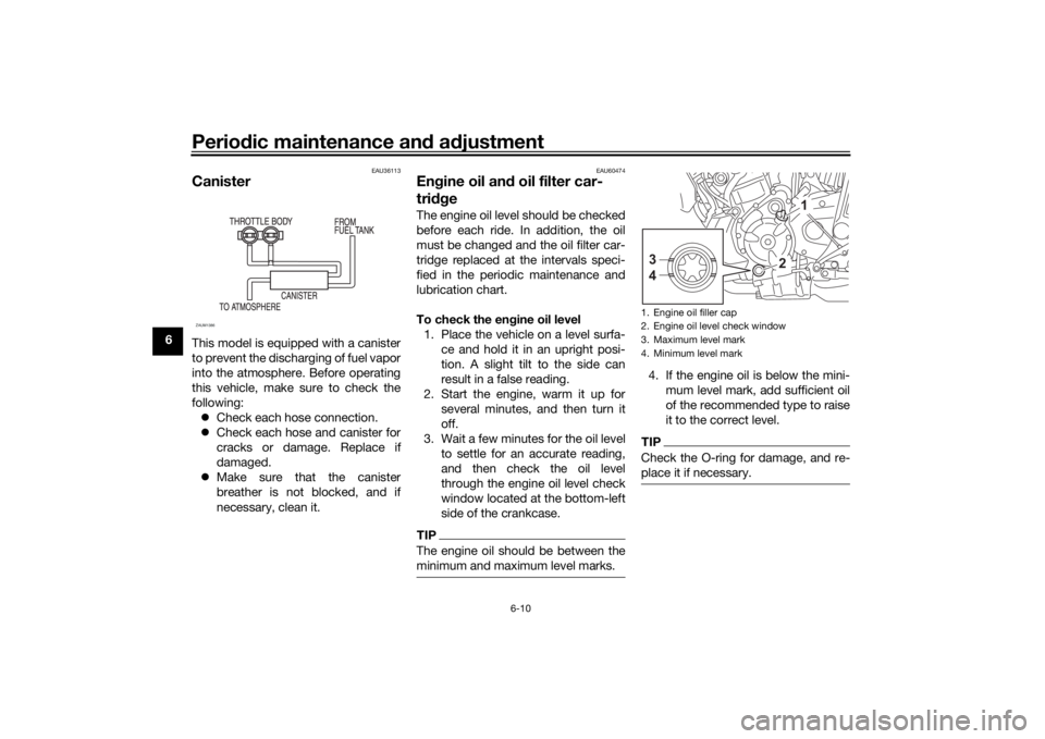
CanisterThis model is equipped with a canister
to prevent the discharging of fuel vapor
into the atmosphere. Before operating
this vehicle, make sure to check the
following:
Check each hose connection.
Check each hose and canister for
cracks or damage. Replace if
damaged.
Make sure that the canister
breather is not blocked, and if
necessary, clean it.
EAU60474
Engine oil an d oil filter car-
tri dgeThe engine oil level should be checked
before each ride. In addition, the oil
must be changed and the oil filter car-
tridge replaced at the intervals speci-
fied in the periodic maintenance and
lubrication chart.
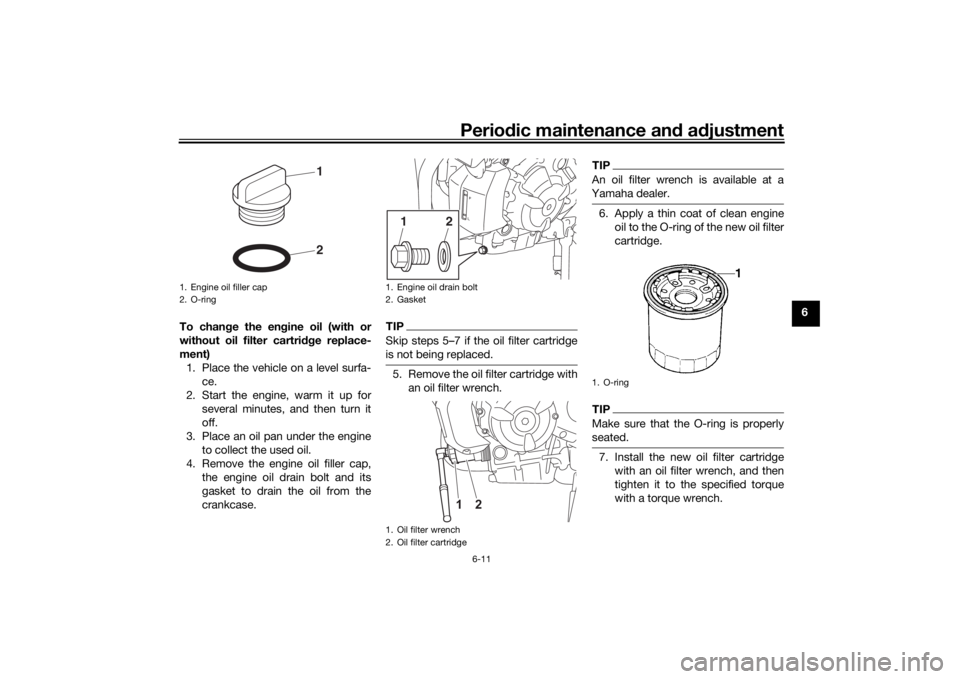
To check the en gine oil level
1. Place the vehicle on a level surfa- ce and hold it in an upright posi-
tion. A slight tilt to the side can
result in a false reading.
2. Start the engine, warm it up for several minutes, and then turn it
off.
3. Wait a few minutes for the oil level to settle for an accurate reading,
and then check the oil level
through the engine oil level check
window located at the bottom-left
side of the crankcase.TIPThe engine oil should be between the
minimum and maximum level marks.
4. If the engine oil is below the mini-mum level mark, add sufficient oil
of the recommended type to raise
it to the correct level.TIPCheck the O-ring for damage, and re-
place it if necessary.
ZAUM1386
1. Engine oil filler cap
2. Engine oil level check window
3. Maximum level mark
4. Minimum level mark
1
2
3
4
UBJVE0E0.book Page 10 Wednesday, December 23, 2020 8:59 AM
Page 57 of 98
Periodic maintenance an d a djustment
6-11
6
To chan ge the en gine oil (with or
without oil filter cartri dge replace-
ment) 1. Place the vehicle on a level surfa- ce.
2. Start the engine, warm it up for several minutes, and then turn it
off.
3. Place an oil pan under the engine to collect the used oil.
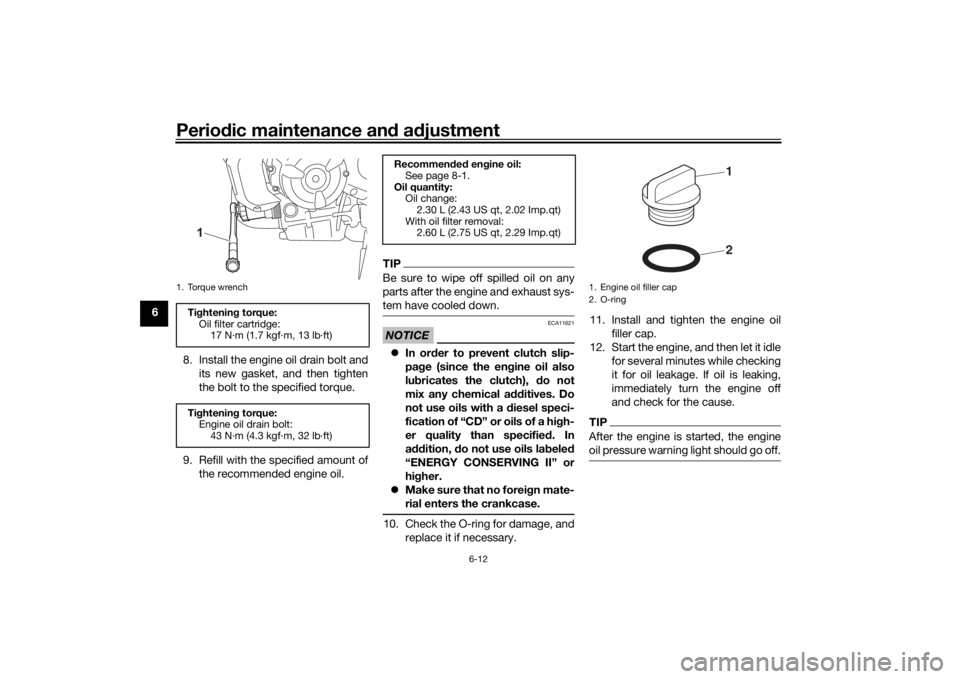
4. Remove the engine oil filler cap, the engine oil drain bolt and its
gasket to drain the oil from the
crankcase.
TIPSkip steps 5–7 if the oil filter cartridge
is not being replaced.5. Remove the oil filter cartridge withan oil filter wrench.
TIPAn oil filter wrench is available at a
Yamaha dealer.6. Apply a thin coat of clean engineoil to the O-ring of the new oil filter
cartridge.TIPMake sure that the O-ring is properly
seated.7. Install the new oil filter cartridgewith an oil filter wrench, and then
tighten it to the specified torque
with a torque wrench.
1. Engine oil filler cap
2. O-ring
21
1. Engine oil drain bolt
2. Gasket
1. Oil filter wrench
2. Oil filter cartridge
2
1
2
1
1. O-ring
UBJVE0E0.book Page 11 Wednesday, December 23, 2020 8:59 AM
Page 58 of 98
Periodic maintenance an d a djustment
6-12
6
8. Install the engine oil drain bolt andits new gasket, and then tighten
the bolt to the specified torque.
9. Refill with the specified amount of the recommended engine oil.
TIPBe sure to wipe off spilled oil on any
parts after the engine and exhaust sys-
tem have cooled down.NOTICE
ECA11621
In or der to prevent clutch slip-
pa ge (since the en gine oil also
lu bricates the clutch), do not
mix any chemical additives. Do
not use oils with a diesel speci-
fication of “CD” or oils of a hi gh-
er quality than specifie d. In
a ddition, do not use oils la beled
“ENERGY CONSERVING II” or
hi gher.
Make sure that no forei gn mate-
rial enters the crankcase.10. Check the O-ring for damage, and replace it if necessary. 11. Install and tighten the engine oil
filler cap.
12. Start the engine, and then let it idle for several minutes while checking
it for oil leakage. If oil is leaking,
immediately turn the engine off
and check for the cause.
TIPAfter the engine is started, the engine
oil pressure warning light should go off.
1. Torque wrenchTightenin g torque:
Oil filter cartridge: 17 N·m (1.7 kgf·m, 13 lb·ft)
Ti ghtenin g torque:
Engine oil drain bolt:
43 N·m (4.3 kgf·m, 32 lb·ft)1
Recommen ded en gine oil:
See page 8-1.
Oil quantity: Oil change:
2.30 L (2.43 US qt, 2.02 Imp.qt)
With oil filter removal: 2.60 L (2.75 US qt, 2.29 Imp.qt)
1. Engine oil filler cap
2. O-ring
21
UBJVE0E0.book Page 12 Wednesday, December 23, 2020 8:59 AM
Page 59 of 98
Periodic maintenance an d a djustment
6-13
6
NOTICE
ECA20860
If the oil pressure warnin g li ght flick-
ers or remains on even if the oil level
is correct, immed iately turn the en-
g ine off an d have a Yamaha d ealer
check the vehicle.13. Turn the engine off, wait a few mi- nutes for the oil level to settle for
an accurate reading, and then
check the oil level and correct it if
necessary.
EAU85450
Why Yamalu beYAMALUBE oil is a Genuine YAMAHA
Part born of the engineers’ passion
and belief that engine oil is an impor-
tant liquid engine component. We form
teams of specialists in the fields of me-
chanical engineering, chemistry, elec-
tronics and track testing, and have
them develop the engine together with
the oil it will use. Yamalube oils take full
advantage of the base oil’s qualities
and blend in the ideal balance of addi-
tives to make sure the final oil clears
our performance standards. Thus,
Yamalube mineral, semisynthetic and
synthetic oils have their own distinct
characters and value. Yamaha’s expe-
rience gained over many years of re-
search and development into oil since
the 1960’s helps make Yamalube the
best choice for your Yamaha engine.
EAUS1203
CoolantThe coolant level should be checked
regularly. In addition, the coolant must
be changed at the intervals specified in
the periodic maintenance chart.TIPIf genuine Yamaha coolant is not avail-
able, use an ethylene glycol antifreeze
containing corrosion inhibitors for alu-
minum engines and mix with distilled
water at a 1:1 ratio.
EAU20097
To check the coolant level
Since the coolant level varies with en-
gine temperature, check when the en-
gine is cold.
1. Park the vehicle on a level surface.
Recommen ded coolant:
YAMALUBE coolant
Coolant quantity: Coolant reservoir (max level mark): 0.25 L (0.26 US qt, 0.22 Imp.qt)
Radiator (including all routes): 1.60 L (1.69 US qt, 1.41 Imp.qt)
UBJVE0E0.book Page 13 Wednesday, December 23, 2020 8:59 AM
Page 68 of 98
Periodic maintenance an d a djustment
6-22
6
Use only the specified b rake flu-
i d ; otherwise, the ru bber seals
may deteriorate, causin g leak-
a g e.
Refill with the same type of
brake flui d. A ddin g a brake flui d
other than DOT 4 may result in a
harmful chemical reaction.
Be careful that water or d ust
d oes not enter the brake flui d
reservoir when refillin g. Water
will si gnificantly lower the boil-
in g point of the flui d an d may re-
sult in vapor lock, an d d irt may
clo g the ABS hy draulic unit
valves.
NOTICE
ECA17641
Brake flui d may damag e painted
surfaces or plastic parts. Always
clean up spille d flui d imme diately.As the brake pads wear, it is normal for
the brake fluid level to gradually go
down. A low brake fluid level may indi-
cate worn brake pads and/or brake
system leakage; therefore, be sure to
check the brake pads for wear and the
brake system for leakage. If the brake fluid level goes down suddenly, have a
Yamaha dealer check the cause before further riding.
EAU22734
Chan gin g the brake flui dHave a Yamaha dealer change the
brake fluid every 2 years. In addition,
have the seals of the master cylinders
and brake calipers, as well as the brake
hoses replaced at the intervals listed
below or sooner if they are damaged or
leaking.
Brake seals: every 2 years
Brake hoses: every 4 years
UBJVE0E0.book Page 22 Wednesday, December 23, 2020 8:59 AM
Page 70 of 98
Periodic maintenance an d a djustment
6-24
6
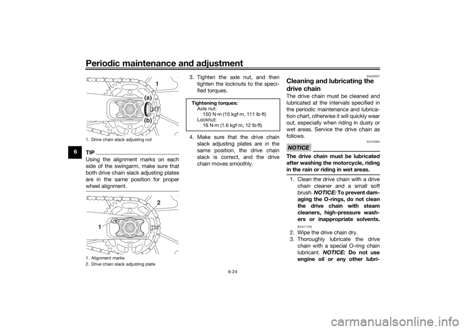
TIPUsing the alignment marks on each
side of the swingarm, make sure that
both drive chain slack adjusting plates
are in the same position for proper
wheel alignment.
3. Tighten the axle nut, and then
tighten the locknuts to the speci-
fied torques.
4. Make sure that the drive chain slack adjusting plates are in the
same position, the drive chain
slack is correct, and the drive
chain moves smoothly.
EAU23027
Cleanin g an d lu bricatin g the
d rive chainThe drive chain must be cleaned and
lubricated at the intervals specified in
the periodic maintenance and lubrica-
tion chart, otherwise it will quickly wear
out, especially when riding in dusty or
wet areas. Service the drive chain as
follows.NOTICE
ECA10584
The drive chain must be lu bricated
after washin g the motorcycle, ri din g
in the rain or ri din g in wet areas.1. Clean the drive chain with a drive
chain cleaner and a small soft
brush. NOTICE: To prevent dam-
a g in g the O-rin gs, do not clean
the drive chain with steam
cleaners, hi gh-pressure wash-
ers or inappropriate solvents.
[ECA11122]
2. Wipe the drive chain dry.
3. Thoroughly lubricate the drive chain with a special O-ring chain
lubricant. NOTICE: Do not use
en gine oil or any other lu bri-
1. Drive chain slack adjusting nut
1. Alignment marks
2. Drive chain slack adjusting plate
1
(a)(b)
2
1
Ti ghtenin g torques:
Axle nut: 150 N·m (15 kgf·m, 111 lb·ft)
Locknut:
16 N·m (1.6 kgf·m, 12 lb·ft)
UBJVE0E0.book Page 24 Wednesday, December 23, 2020 8:59 AM
Page 74 of 98
Periodic maintenance an d a djustment
6-28
6
EAUM1653
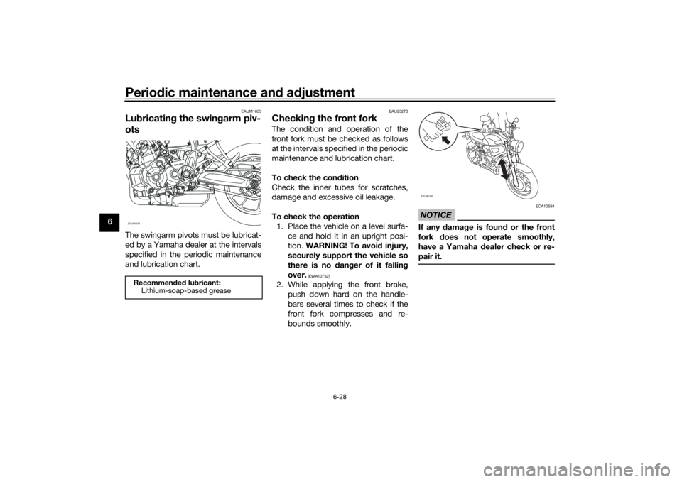
Lub ricatin g the swin garm piv-
otsThe swingarm pivots must be lubricat-
ed by a Yamaha dealer at the intervals
specified in the periodic maintenance
and lubrication chart.
EAU23273
Checkin g the front forkThe condition and operation of the
front fork must be checked as follows
at the intervals specified in the periodic
maintenance and lubrication chart.
To check the con dition
Check the inner tubes for scratches,
damage and excessive oil leakage.
To check the operation 1. Place the vehicle on a level surfa- ce and hold it in an upright posi-
tion. WARNING! To avoi d injury,
securely support the vehicle so
there is no dan ger of it fallin g
over.
[EWA10752]
2. While applying the front brake, push down hard on the handle-
bars several times to check if the
front fork compresses and re-
bounds smoothly.
NOTICE
ECA10591
If any d amage is foun d or the front
fork does not operate smoothly,
have a Yamaha dealer check or re-
pair it.
Recommen ded lu bricant:
Lithium-soap-based greaseZAUM1978
ZAUM1352
UBJVE0E0.book Page 28 Wednesday, December 23, 2020 8:59 AM
Page 79 of 98
Periodic maintenance an d a djustment
6-33
6
use a fuse of a hi
gher ampera ge
ratin g than recommen ded to
avoi d causin g extensive dam-
a g e to the electrical system an d
possi bly a fire.
[EWA15132]
3. Turn the main switch on and turn
on the electrical circuit in question
to check if the device operates.
4. If the fuse immediately blows again, have a Yamaha dealer
check the electrical system.
5. After the fuse is changed, place the battery cover in the original
position, and then install the bolts.
6. Install the diagnostic connector by pushing it downward.
7. Install the seat holder by installing the bolts, and then tighten the
bolts to the specified torque.
8. Install the seat.
EAU34387
Replacin g the hea dlig ht bul bThis model is equipped with a halogen
bulb headlight. If the headlight bulb
burns out, replace it as follows.NOTICE
ECA26690
Do not touch the glass part of
the hea dlig ht bul b. Otherwise
the luminosity an d the life of the
b ul b may b e adversely affected .
Thorou ghly clean off any d irt,
oil, or fin gerprints from the bul b
usin g a cloth moistene d with al-
cohol or thinner.
Do not use a hea dlig ht bul b of a
watta ge hi gher than specified .
Do not affix any type of tinted
film or stickers to the hea dlig ht
lens.
Specifie d fuses:
Main fuse: 30.0 A
Auxiliary fuse:
2.0 A
Headlight fuse: 15.0 A
Signaling system fuse: 10.0 A
Hazard fuse:
7.5 A
Ignition fuse: 10.0 A
Radiator fan motor fuse: 10.0 A
ABS motor fuse:
30.0 A
ABS solenoid fuse: 20.0 A
ABS control unit fuse: 7.5 A
Backup fuse:
7.5 A
Backup fuse 2: 10.0 A
Tightenin g torque:
Seat holder bolts: 7 N·m (0.7 kgf·m, 5.2 lb·ft)
UBJVE0E0.book Page 33 Wednesday, December 23, 2020 8:59 AM
Page 87 of 98

Motorcycle care and stora ge
7-2
7
chemicals such as, solvents,
g
asoline, rust removers, b rake
flui d, or antifreeze, etc.
Before washin g
1. Park the vehicle out of direct sun- light and allow it to cool. This will
help avoid water spots.
2. Make sure all caps, covers, elec- trical couplers and connectors are
tightly installed.
3. Cover the muffler end with a plas- tic bag and a strong rubber band.
4. Pre-soak stubborn stains like in- sects or bird droppings with a wet
towel for a few minutes.
5. Remove road grime and oil stains with a quality degreasing agent
and a plastic-bristle brush or
sponge. NOTICE: Do not use
d eg reasin g a gent on areas re-
quirin g lu brication such as
seals, gaskets, an d wheel axles.
Follow pro duct instructions.
[ECA26290]
Washin g
1. Rinse off any degreaser and spray down the vehicle with a garden
hose. Use only enough pressure
to do the job. Avoid spraying wa-
ter directly into the muffler, instru-
ment panel, air inlet, or other inner
areas such as underseat storage
compartments.
2. Wash the vehicle with a quality au- tomotive-type detergent mixed
with cool water and a soft, clean
towel or sponge. Use an old tooth-
brush or plastic-bristle brush for
hard-to-reach places. NOTICE:
Use col d water if the vehicle has
b een exposed to salt. Warm wa-
ter will increase salt’s corrosive
properties.
[ECA26301]
3. For windshield-equipped vehicles: Clean the windshield with a soft
towel or sponge dampened with
water and a pH neutral detergent.
If necessary, use a high-quality
windshield cleaner or polish for
motorcycles. NOTICE: Never use
any stron g chemicals to clean
the wind shield. Additionally,
some cleanin g compoun ds for plastic may scratch the win
d-
shiel d, so b e sure to test all
cleanin g pro ducts before gen-
eral application.
[ECA26310]
4. Rinse off thoroughly with clean water. Be sure to remove all deter-
gent residues, as they can be
harmful to plastic parts.
After washin g
1. Dry the vehicle with a chamois or absorbent towel, preferably mi-
crofiber terrycloth.
2. For drive chain-equipped models: Dry and then lubricate the drive
chain to prevent rust.
3. Use a chrome polish to shine chrome, aluminum, and stainless
steel parts. Often the thermally in-
duced discoloring of stainless
steel exhaust systems can be re-
moved through polishing.
4. Apply a corrosion protection spray on all metal parts including
chrome or nickel-plated surfaces.
WARNING! Do not apply sili- cone or oil spray to seats, han d
g rips, ru bber foot pe gs or tire
trea ds. Otherwise these parts
UBJVE0E0.book Page 2 Wednesday, December 23, 2020 8:59 AM
Page 89 of 98
Motorcycle care and stora ge
7-4
7
1. Make all necessary repairs and
perform any outstanding mainte-
nance.
2. Follow all instructions in the Care section of this chapter.
3. Fill up the fuel tank, adding fuel stabilizer according to product in-
structions. Run the engine for 5
minutes to distribute treated fuel
through the fuel system.
4. For vehicles equipped with a fuel cock: Turn the fuel cock lever to
the off position.
5. For vehicles with a carburetor: To prevent fuel deposits from build-
ing up, drain the fuel in the carbu-
retor float chamber into a clean
container. Retighten the drain bolt
and pour the fuel back into the fuel
tank.
6. Use a quality engine fogging oil according to product instructions
to protect internal engine compo-
nents from corrosion. If engine
fogging oil is not available, per-
form the following steps for each
cylinder:a. Remove the spark plug cap and spark plug. b. Pour a teaspoonful of engine
oil into the spark plug bore.
c. Install the spark plug cap onto the spark plug, and then place
the spark plug on the cylinder
head so that the electrodes are
grounded. (This will limit spark-
ing during the next step.)
d. Turn the engine over several times with the starter. (This will
coat the cylinder wall with oil.)
WARNING! To prevent dam-
a g e or injury from sparkin g,
make sure to groun d the
spark plu g electro des while
turnin g the en gine over.
[EWA10952]
e. Remove the spark plug cap
from the spark plug, and then
install the spark plug and the
spark plug cap.
7. Lubricate all control cables, piv- ots, levers and pedals, as well as
the sidestand and centerstand (if
equipped).
8. Check and correct the tire air pressure, and then lift the vehicle
so that all wheels are off the
ground. Otherwise, turn the wheels a little once a month in or-
der to prevent the tires from be-
coming degraded in one spot.
9. Cover the muffler outlet with a plastic bag to prevent moisture
from entering it.
10. Remove the battery and fully char- ge it, or attach a maintenance
charger to keep the battery opti-
mally charged. NOTICE: Confirm
that the battery an d its char ger
are compati ble. Do not char ge a
VRLA battery with a convention-
al char ger.
[ECA26330]
TIP If the battery will be removed,
charge it once a month and store
it in a temperate location between
0-30 °C (32-90 °F).
See page 6-29 for more informa-
tion on charging and storing the
battery.
UBJVE0E0.book Page 4 Wednesday, December 23, 2020 8:59 AM