seat YAMAHA XSR 900 2016 Owners Manual
[x] Cancel search | Manufacturer: YAMAHA, Model Year: 2016, Model line: XSR 900, Model: YAMAHA XSR 900 2016Pages: 106, PDF Size: 7.68 MB
Page 6 of 106

Table of contentsSafety information............................ 1-1
Description ........................................ 2-1
Left view .......................................... 2-1
Right view ........................................ 2-2
Controls and instrument s................. 2-3
Instrument and co ntrol functions.... 3-1
Immobilizer system ....... ................... 3-1
Main switch/steering lock................. 3-2
Indicator lights and warning lights ... 3-4
Multi-function meter unit .................. 3-6
D-mode (drive mode)..................... 3-13
Handlebar switches ....................... 3-14
Clutch lever.................................... 3-16
Shift pedal....... ............................. .. 3-16
Brake lever .................................... 3-16
Brake pedal ................................... 3-17
ABS ............................................... 3-17
Traction control system ................. 3-18
Fuel tank cap ................................. 3-20
Fuel................................................ 3-20
Fuel tank breather hose and overflow hose ............................. 3-22
Catalytic converter ......................... 3-22
Seat ............................................... 3-23
Storage compartment .................... 3-23
Adjusting the front fork................... 3-24
Adjusting the shock absorber assembly .................................... 3-25
Luggage strap holders ................... 3-27 Sidestand ...................................... 3-27
Ignition circuit cut-
off system ......... 3-28
Auxiliary DC connector.................. 3-30
For your safety – pre-operation
checks ............................................... 4-1
Operation and important riding
points ................................................. 5-1
Starting the engine .......................... 5-1
Shifting ............................................ 5-2
Tips for reducing fuel consumption ................................ 5-4
Engine break-in ............................... 5-4
Parking ............................................ 5-5
Periodic maintenance and
adjustment ........................................ 6-1
Owner’s tool kit................................ 6-2
Periodic maintenance chart for the
emission control system .............. 6-3
General maintenance and lubrication chart ........................... 6-4
Checking the spark plugs ................ 6-8
Canister ........................................... 6-9
Engine oil and oil filter cartridge ...... 6-9
Coolant .......................................... 6-12
Air filter element ............................ 6-15
Checking the engine idling speed ......................................... 6-15 Checking the throttle grip free
play ............................................. 6-15
Valve clearance ............................. 6-16
Tires ............................................... 6-16
Cast wheels ................................... 6-18
Adjusting the clutch lever free play ............................................. 6-19
Checking the brake lever free
play ............................................. 6-19
Brake light switches ....................... 6-20
Checking the front and rear brake
pads............................................ 6-20
Checking the brake fluid level ........ 6-21
Changing the brake fluid ................ 6-22
Drive chain slack............................ 6-23
Cleaning and lubricating the drive chain .................................. 6-24
Checking and lubricating the cables ......................................... 6-25
Checking and lubricating the
throttle grip and cable ................. 6-25
Checking and lubricating the brake and shift pedals ................ 6-26
Checking and lubricating the brake and clutch levers .............. 6-26
Checking and lubricating the sidestand .................................... 6-27
Lubricating the swingarm pivots .... 6-27
Checking the front fork................... 6-28
Checking the steering .................... 6-28
Checking the wheel bearings......... 6-29B90-9-E0_1.book 1 ページ 2015年12月15日 火曜日 午後8時5分
Page 9 of 106
Safety information
1-2
12
3
4
5
6
7
8
9
10
11
12
tice riding your motorcycle
where there is no traffic until you
have become thoroughly famil-
iar with the motorcycle and all of
its controls.
Many accidents have been caused
by error of the motorcycle opera-
tor. A typical error made by the op-
erator is veering wide on a turn
due to excessive speed or under-
cornering (insufficient lean angle
for the speed).
Always obey the speed limit and
never travel faster than warrant-
ed by road and traffic conditions.
Always signal before turning or changing lanes. Make sure that
other motorists can see you.
The posture of the operator and
passenger is important for proper
control.
The operator should keep bothhands on the handlebar and
both feet on the operator foot-
rests during operation to main-
tain control of the motorcycle.
The passenger should always hold onto the operator, the seat
strap or grab bar, if equipped, with both hands and keep both
feet on the passenger footrests.
Never carry a passenger unless
he or she can firmly place both
feet on the passenger footrests.
Never ride under the influence of
alcohol or other drugs.
This motorcycle is designed for
on-road use only. It is not suitable
for off-road use.
Protective Apparel
The majority of fatalities from motorcy-
cle accidents are the result of head in-
juries. The use of a safety helmet is the
single most critical factor in the preven-
tion or reduction of head injuries.
Always wear an approved helmet.
Wear a face shield or goggles.
Wind in your unprotected eyes
could contribute to an impairment
of vision that could delay seeing a
hazard.
The use of a jacket, heavy boots,
trousers, gloves, etc., is effective in
preventing or reducing abrasions
or lacerations.
Never wear loose-fitting clothes,
otherwise they could catch on the control levers, footrests, or wheels
and cause injury or an accident.
Always wear protective clothing
that covers your legs, ankles, and
feet. The engine or exhaust sys-
tem become very hot during or af-
ter operation and can cause burns.
A passenger should also observe
the above precautions.
Avoid Carbon Monoxide Poisoning
All engine exhaust contains carbon
monoxide, a deadly gas. Breathing car-
bon monoxide can cause headaches,
dizziness, drowsiness, nausea, confu-
sion, and eventually death.
Carbon Monoxide is a colorless, odor-
less, tasteless gas which may be pres-
ent even if you do not see or smell any
engine exhaust. Deadly levels of car-
bon monoxide can collect rapidly and
you can quickly be overcome and un-
able to save yourself. Also, deadly lev-
els of carbon monoxide can linger for
hours or days in enclosed or poorly
ventilated areas. If you experience any
symptoms of carbon monoxide poison-
ing, leave the area immediately, get
fresh air, and SEEK MEDICAL TREAT-
B90-9-E0_1.book 2 ページ 2015年12月15日 火曜日 午後8時5分
Page 13 of 106
2-1
123
4
5
6
7
8
9
10
11
12
Description
EAU10411
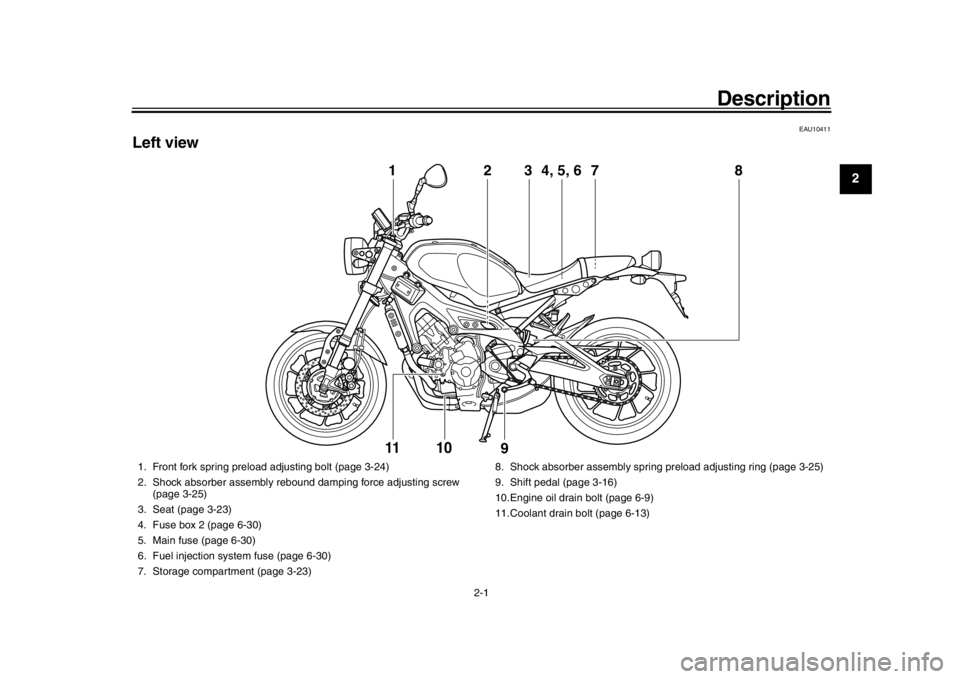
Left view
2
1
3
7
4, 5, 6
8
9
11
10
1. Front fork spring preload adjusting bolt (page 3-24)
2. Shock absorber assembly rebound damping force adjusting screw (page 3-25)
3. Seat (page 3-23)
4. Fuse box 2 (page 6-30)
5. Main fuse (page 6-30)
6. Fuel injection system fuse (page 6-30)
7. Storage compartment (page 3-23) 8. Shock absorber assembly spring
preload adjusting ring (page 3-25)
9. Shift pedal (page 3-16)
10.Engine oil drain bolt (page 6-9)
11.Coolant drain bolt (page 6-13)
B90-9-E0_1.book 1 ページ 2015年12月15日 火曜日 午後8時5分
Page 38 of 106
Instrument and control functions
3-23
1
23
4
5
6
7
8
9
10
11
12
EAU57991
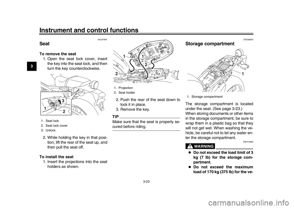
SeatTo remove the seat 1. Open the seat lock cover, insert the key into the seat lock, and then
turn the key counterclockwise.
2. While holding the key in that posi- tion, lift the rear of the seat up, and
then pull the seat off.
To install the seat 1. Insert the projections into the seat holders as shown. 2. Push the rear of the seat down to
lock it in place.
3. Remove the key.
TIPMake sure that the seat is properly se-cured before riding.
EAU58200
Storage compartmentThe storage compartment is located
under the seat. (See page 3-23.)
When storing documents or other items
in the storage compartment, be sure to
wrap them in a plastic bag so that they
will not get wet. When washing the ve-
hicle, be careful not to let any water en-
ter the storage compartment.
WARNING
EWA10962
Do not exceed the load limit of 3
kg (7 lb) for the storage com-
partment.
Do not exceed the maximum
load of 170 kg (375 lb) for the ve-
1. Seat lock
2. Seat lock cover
3. Unlock.1
32
1. Projection
2. Seat holder
11
2
2
1. Storage compartment
1
B90-9-E0_1.book 23 ページ 2015年12月15日 火曜日 午後8時5分
Page 55 of 106
Periodic maintenance and adjustment
6-2
1
2
3
4
567
8
9
10
11
12
EAU39692
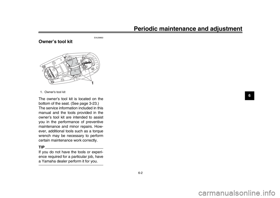
Owner’s tool kitThe owner’s tool kit is located on the
bottom of the seat. (See page 3-23.)
The service information included in this
manual and the tools provided in the
owner’s tool kit are intended to assist
you in the performance of preventive
maintenance and minor repairs. How-
ever, additional tools such as a torque
wrench may be necessary to perform
certain maintenance work correctly.TIPIf you do not have the tools or experi-
ence required for a particular job, havea Yamaha dealer perform it for you.1. Owner’s tool kit
1
B90-9-E0_1.book 2 ページ 2015年12月15日 火曜日 午後8時5分
Page 63 of 106
Periodic maintenance and adjustment6-10
1
2
3
4
567
8
9
10
11
12
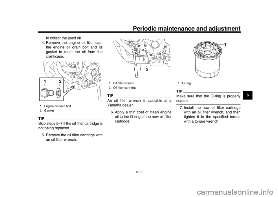
to collect the used oil.
4. Remove the engine oil filler cap, the engine oil drain bolt and its
gasket to drain the oil from the
crankcase.
TIPSkip steps 5–7 if the oil filter cartridge isnot being replaced.
5. Remove the oil filter cartridge with an oil filter wrench.
TIPAn oil filter wrench is available at aYamaha dealer.
6. Apply a thin coat of clean engine oil to the O-ring of the new oil filter
cartridge.
TIPMake sure that the O-ring is properlyseated.
7. Install the new oil filter cartridge with an oil filter wrench, and then
tighten it to the specified torque
with a torque wrench.
1. Engine oil drain bolt
2. Gasket
21
1. Oil filter wrench
2. Oil filter cartridge
2
1
1. O-ring
B90-9-E0_1.book 10 ページ 2015年12月15日 火曜日 午後8時5分
Page 82 of 106
Periodic maintenance and adjustment
6-29
1
2
3
4
56
7
8
9
10
11
12
EAU23292
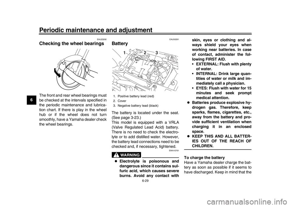
Checking the wheel bearingsThe front and rear wheel bearings must
be checked at the intervals specified in
the periodic maintenance and lubrica-
tion chart. If there is play in the wheel
hub or if the wheel does not turn
smoothly, have a Yamaha dealer check
the wheel bearings.
EAU50291
BatteryThe battery is located under the seat.
(See page 3-23.)
This model is equipped with a VRLA
(Valve Regulated Lead Acid) battery.
There is no need to check the electro-
lyte or to add distilled water. However,
the battery lead connections need to be
checked and, if necessary, tightened.
WARNING
EWA10761
Electrolyte is poisonous and
dangerous since it contains sul-
furic acid, which causes severe
burns. Avoid any contact with skin, eyes or clothing and al-
ways shield your eyes when
working near batteries. In case
of contact, administer the fol-
lowing FIRST AID.
• EXTERNAL: Flush with plenty
of water.
INTERNAL: Drink large quan- tities of water or milk and im-
mediately call a physician.
EYES: Flush with water for 15 minutes and seek prompt
medical attention.
Batteries produce explosive hy-
drogen gas. Therefore, keep
sparks, flames, cigarettes, etc.,
away from the battery and pro-
vide sufficient ventilation when
charging it in an enclosed
space.
KEEP THIS AND ALL BATTER-
IES OUT OF THE REACH OFCHILDREN.
To charge the battery
Have a Yamaha dealer charge the bat-
tery as soon as possible if it seems to
have discharged. Keep in mind that the
1. Positive battery lead (red)
2. Cover
3. Negative battery lead (black)
2
13
B90-9-E0_1.book 29 ページ 2015年12月15日 火曜日 午後8時5分
Page 84 of 106
Periodic maintenance and adjustment
6-31
1
2
3
4
56
7
8
9
10
11
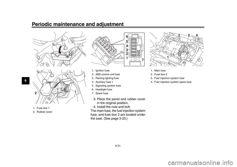
12 3. Place the panel and rubber cover
in the original position.
4. Install the nuts and bolt.
The main fuse, the fuel injection system
fuse, and fuse box 2 are located under
the seat. (See page 3-23.)
1. Fuse box 1
2. Rubber cover
1
2
1. Ignition fuse
2. ABS control unit fuse
3. Parking lighting fuse
4. Auxiliary fuse 1
5. Signaling system fuse
6. Headlight fuse
7. Spare fuse
7
1 2 3 4 5 6
1. Main fuse
2. Fuse box 2
3. Fuel injection system fuse
4. Fuel injection system spare fuse
2
1 3
4
B90-9-E0_1.book 31 ページ 2015年12月15日 火曜日 午後8時5分
Page 97 of 106
8-1
1
2
3
4
5
6
789
10
11
12
Specifications
EAU69993
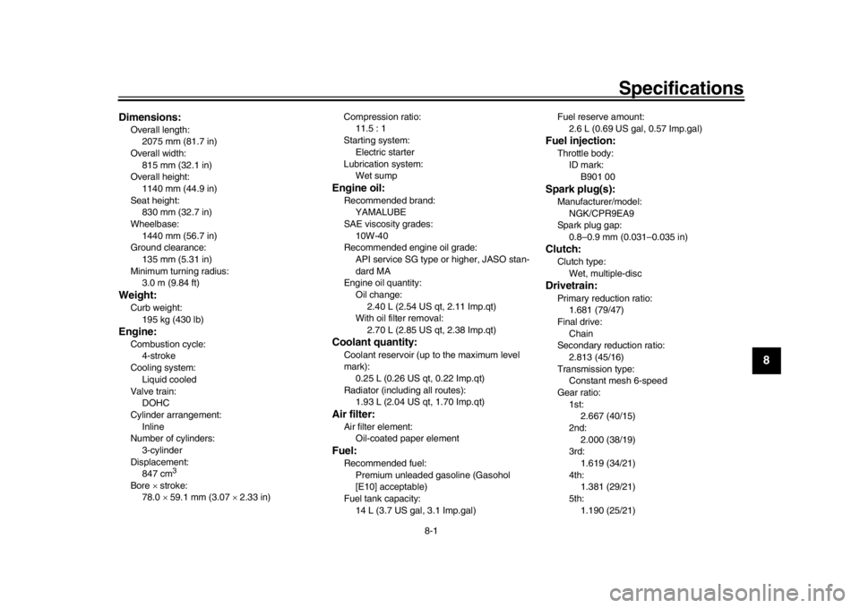
Dimensions:Overall length: 2075 mm (81.7 in)
Overall width: 815 mm (32.1 in)
Overall height: 1140 mm (44.9 in)
Seat height:
830 mm (32.7 in)
Wheelbase: 1440 mm (56.7 in)
Ground clearance: 135 mm (5.31 in)
Minimum turning radius:
3.0 m (9.84 ft)Weight:Curb weight:195 kg (430 lb)Engine:Combustion cycle:4-stroke
Cooling system: Liquid cooled
Valve train:
DOHC
Cylinder arrangement: Inline
Number of cylinders: 3-cylinder
Displacement:
847 cm
3
Bore stroke:
78.0 59.1 mm (3.07 2.33 in) Compression ratio:
11.5 : 1
Starting system:
Electric starter
Lubrication system: Wet sump
Engine oil:Recommended brand:
YAMALUBE
SAE viscosity grades: 10W-40
Recommended engine oil grade: API service SG type or higher, JASO stan-
dard MA
Engine oil quantity: Oil change:2.40 L (2.54 US qt, 2.11 Imp.qt)
With oil filter removal: 2.70 L (2.85 US qt, 2.38 Imp.qt)Coolant quantity:Coolant reservoir (up to the maximum level
mark):
0.25 L (0.26 US qt, 0.22 Imp.qt)
Radiator (including all routes): 1.93 L (2.04 US qt, 1.70 Imp.qt)Air filter:Air filter element:
Oil-coated paper elementFuel:Recommended fuel:Premium unleaded gasoline (Gasohol
[E10] acceptable)
Fuel tank capacity: 14 L (3.7 US gal, 3.1 Imp.gal) Fuel reserve amount:
2.6 L (0.69 US gal, 0.57 Imp.gal)
Fuel injection:Throttle body:ID mark:
B901 00Spark plug(s):Manufacturer/model: NGK/CPR9EA9
Spark plug gap:
0.8–0.9 mm (0.031–0.035 in)Clutch:Clutch type:Wet, multiple-discDrivetrain:Primary reduction ratio:1.681 (79/47)
Final drive: Chain
Secondary reduction ratio:
2.813 (45/16)
Transmission type: Constant mesh 6-speed
Gear ratio: 1st:2.667 (40/15)
2nd: 2.000 (38/19)
3rd:
1.619 (34/21)
4th: 1.381 (29/21)
5th: 1.190 (25/21)
B90-9-E0_1.book 1 ページ 2015年12月15日 火曜日 午後8時5分
Page 101 of 106
Consumer information
9-2
1
2
3
4
5
6
7
8910
11
12
EAU26481
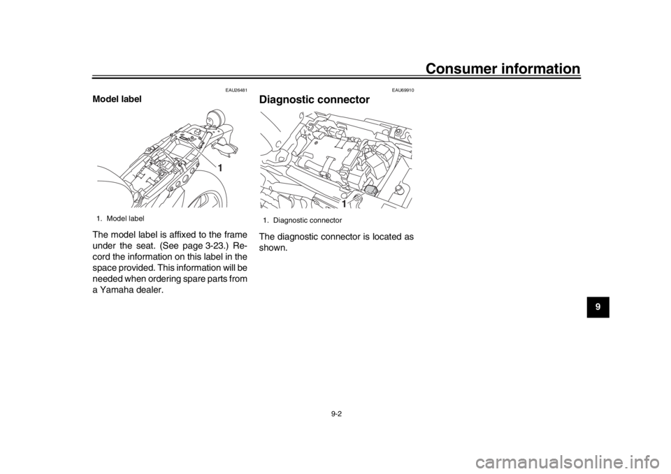
Model label
The model label is affixed to the frame
under the seat. (See page 3-23.) Re-
cord the information on this label in the
space provided. This information will be
needed when ordering spare parts from
a Yamaha dealer.
EAU69910
Diagnostic connectorThe diagnostic connector is located as
shown.
1. Model label
1
1. Diagnostic connector
1
B90-9-E0_1.book 2 ページ 2015年12月15日 火曜日 午後8時5分