load YAMAHA XT1200Z 2014 Owners Manual
[x] Cancel search | Manufacturer: YAMAHA, Model Year: 2014, Model line: XT1200Z, Model: YAMAHA XT1200Z 2014Pages: 116, PDF Size: 3.11 MB
Page 10 of 116
SAFETY INFORMATION
1-3
1Carbon Monoxide is a colorless, odor-
less, tasteless gas which may be pres-
ent even if you do not see or smell any
engine exhaust. Deadly levels of car-
bon monoxide can collect rapidly and
you can quickly be overcome and un-
able to save yourself. Also, deadly lev-
els of carbon monoxide can linger for
hours or days in enclosed or poorly
ventilated areas. If you experience any
symptoms of carbon monoxide poi-
soning, leave the area immediately, get
fresh air, and SEEK MEDICAL TREAT-
MENT.
Do not run engine indoors. Even if
you try to ventilate engine exhaust
with fans or open windows and
doors, carbon monoxide can rap-
idly reach dangerous levels.
Do not run engine in poorly venti-
lated or partially enclosed areas
such as barns, garages, or car-
ports.
Do not run engine outdoors where
engine exhaust can be drawn into
a building through openings such
as windows and doors. Loa
din g
Adding accessories or cargo to your
motorcycle can adversely affect stabil-
ity and handling if the weight distribu-
tion of the motorcycle is changed. To
avoid the possibility of an accident, use
extreme caution when adding cargo or
accessories to your motorcycle. Use
extra care when riding a motorcycle
that has added cargo or accessories.
Here, along with the information about
accessories below, are some general
guidelines to follow if loading cargo to
your motorcycle:
The total weight of the operator, pas-
senger, accessories and cargo must
not exceed the maximum load limit.
Operation of an overloa ded vehicle
coul d cause an acci dent.
When loading within this weight limit,
keep the following in mind: Cargo and accessory weight
should be kept as low and close to
the motorcycle as possible. Se-
curely pack your heaviest items as close to the center of the vehicle
as possible and make sure to dis-
tribute the weight as evenly as
possible on both sides of the mo-
torcycle to minimize imbalance or
instability.
Shifting weights can create a sud-
den imbalance. Make sure that
accessories and cargo are se-
curely attached to the motorcycle
before riding. Check accessory
mounts and cargo restraints fre-
quently.
• Properly adjust the suspension for your load (suspension-ad-
justable models only), and
check the condition and pres-
sure of your tires.
• Never attach any large or heavy items to the handlebar, front
fork, or front fender. These
items, including such cargo as
sleeping bags, duffel bags, or
tents, can create unstable han-
dling or a slow steering re-
sponse.
This vehicle is not desi gne d to
pull a trailer or to be attached to
a si decar.
Maximum loa d:
213 kg (470 lb)
U2BSE0E0.book Page 3 Tuesday, September 17, 2013 8:55 AM
Page 11 of 116

SAFETY INFORMATION
1-4
1
Genuine Yamaha Accessories
Choosing accessories for your vehicle
is an important decision. Genuine
Yamaha accessories, which are avail- able only from a Yamaha dealer, have
been designed, tested, and approved
by Yamaha for use on your vehicle.
Many companies with no connection
to Yamaha manufacture parts and ac-
cessories or offer other modifications
for Yamaha vehicles. Yamaha is not in
a position to test the products that
these aftermarket companies produce.
Therefore, Yamaha can neither en-
dorse nor recommend the use of ac-
cessories not sold by Yamaha or
modifications not specifically recom-
mended by Yamaha, even if sold and
installed by a Yamaha dealer.
Aftermarket Parts, Accessories, an d
Mo difications
While you may find aftermarket prod-
ucts similar in design and quality to
genuine Yamaha accessories, recog-
nize that some aftermarket accesso-
ries or modifications are not suitable
because of potential safety hazards to
you or others. Installing aftermarket products or having other modifications
performed to your vehicle that change
any of the vehicle’s design or operation
characteristics can put you and others
at greater risk of serious injury or
death. You are responsible for injuries
related to changes in the vehicle.
Keep the following guidelines in mind,
as well as those provided under “Load-
ing” when mounting accessories.
Never install accessories or carry
cargo that would impair the per-
formance of your motorcycle.
Carefully inspect the accessory
before using it to make sure that it
does not in any way reduce
ground clearance or cornering
clearance, limit suspension travel,
steering travel or control opera-
tion, or obscure lights or reflec-
tors.
• Accessories fitted to the han- dlebar or the front fork area can
create instability due to improp-
er weight distribution or aerody-
namic changes. If accessories
are added to the handlebar or front fork area, they must be as
lightweight as possible and
should be kept to a minimum.
• Bulky or large accessories may seriously affect the stability of
the motorcycle due to aerody-
namic effects. Wind may at-
tempt to lift the motorcycle, or
the motorcycle may become
unstable in cross winds. These
accessories may also cause in-
stability when passing or being
passed by large vehicles.
• Certain accessories can dis- place the operator from his or
her normal riding position. This
improper position limits the
freedom of movement of the
operator and may limit control
ability, therefore, such accesso-
ries are not recommended.
Use caution when adding electri-
cal accessories. If electrical ac-
cessories exceed the capacity of
the motorcycle’s electrical sys-
tem, an electric failure could re-
sult, which could cause a
dangerous loss of lights or engine
power.
U2BSE0E0.book Page 4 Tuesday, September 17, 2013 8:55 AM
Page 14 of 116

DESCRIPTION
2-2
2
EAU10421
Right view
1
8
7
9
12
13
10
11
2
3,4
5
6
1. Rear brake fluid reservoir (page 6-23)
2. Shock absorber assembly spring preload adjusting knob (page 3-37)
3. Front fork rebound damping force adjusting screw (page 3-35)
4. Front fork spring preload adjusting bolt (page 3-35)
5. Fuses (page 6-30)
6. Fuse box (page 6-30)
7. Front fork compression damping force adjusting screw (page 3-35)
8. Owner’s tool kit (page 6-2) 9. Battery (page 6-29)
10.Engine oil filler cap (page 6-11)
11.Engine oil level check window (page 6-11)
12.Brake pedal (page 3-26)
13.Shock absorber assembly rebound damping force adjusting knob
(page 3-37)U2BSE0E0.book Page 2 Tuesday, September 17, 2013 8:55 AM
Page 29 of 116

INSTRUMENT AND CONTROL FUNCTIONS
3-14
3
“RESET” button briefly so that the trip-
meter flashes, and then push the “RE-
SET” button again for at least 2
seconds while the tripmeter is flashing.
If you do not reset the fuel reserve trip-
meter manually, it will reset itself auto-
matically and the display will return to
the prior mode after refueling and trav-
eling 5 km (3 mi).
Estimated traveling range display:
The distance that can be traveled with
the remaining fuel in the fuel tank under
the current riding conditions is shown.
Elapsed time display:The time that has elapsed since the
key was turned to “ON” is shown. The
maximum time that can be shown is
99:59. This display is automatically reset
when the key is turned to “OFF”.
TIPThere are also “TIME–2” and “TIME–3”
elapsed time displays, but they cannot
be set to the information display. See
“Setting mode” on page 3-16 for de-
tailed information.Air intake temperature display:The air intake temperature display indi-
cates the temperature of the air drawn
into the air filter case.
This display shows the air intake tem-
perature from –9 °C to 93 °C in 1 °C in-
crements. The temperature displayed
may vary from the ambient tempera-
ture.TIP
–9 °C will be displayed even if the
air intake temperature falls below
–9 °C.
The accuracy of the temperature
reading may be affected when rid-
ing slowly [approximately under
20 km/h (12.5 mi/h)] or when
stopped at traffic signals, railroad
crossings, etc.
Coolant temperature display:The coolant temperature display indi-
cates the temperature of the coolant.
The coolant temperature varies with
changes in the weather and engine
load.
If the message “Hi” flashes, stop the
vehicle, then stop the engine, and let
the engine cool. (See page 6-39.)
11
RANGE km
0:06
TIME TRIP
25
A.TEMP ˚C
Lo
C.TEMP˚C
U2BSE0E0.book Page 14 Tuesday, September 17, 2013 8:55 AM
Page 50 of 116

INSTRUMENT AND CONTROL FUNCTIONS
3-35
33. Align the slide plate holders withthe match marks at the desired
position.
TIPMake sure that the slide plate
holders are aligned with the match
marks at the same height on both
sides of the windshield.
Make sure that the projection on
each slide plate holder fits into the
corresponding hole in the slide
plate.
4. Tighten the adjusting knobs.
EAU59140
Adjustin g the front fork
WARNING
EWA10181
Always a djust both fork le gs equally,
otherwise poor han dlin g an d loss of
sta bility may result.This front fork is equipped with spring
preload adjusting bolts, rebound
damping force adjusting screws and
compression damping force adjusting
screws.NOTICE
ECA10102
To avoi d d amag ing the mechanism,
d o not attempt to turn b eyond the
maximum or minimum settin gs.Sprin g preloa d
To increase the spring preload and
thereby harden the suspension, turn
the adjusting bolt on each fork leg in di-
rection (a). To decrease the spring pre-
load and thereby soften the
suspension, turn the adjusting bolt on
each fork leg in direction (b).
1. Slide plate holder
1
1. Match mark
2. Slide plate
2
1
U2BSE0E0.book Page 35 Tuesday, September 17, 2013 8:55 AM
Page 51 of 116
INSTRUMENT AND CONTROL FUNCTIONS
3-36
3
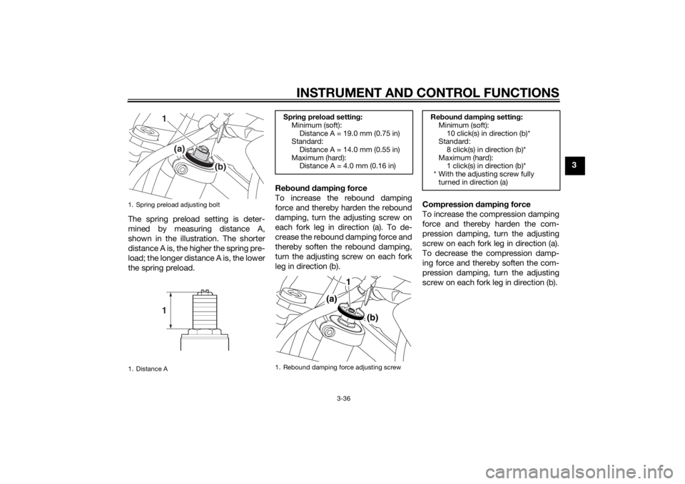
The spring preload setting is deter-
mined by measuring distance A,
shown in the illustration. The shorter
distance A is, the higher the spring pre-
load; the longer distance A is, the lower
the spring preload. Re
boun d d ampin g force
To increase the rebound damping
force and thereby harden the rebound
damping, turn the adjusting screw on
each fork leg in direction (a). To de-
crease the rebound damping force and
thereby soften the rebound damping,
turn the adjusting screw on each fork
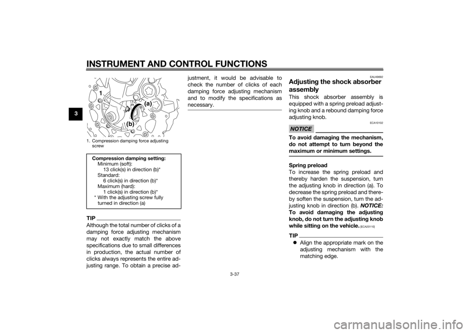
leg in direction (b). Compression
dampin g force
To increase the compression damping
force and thereby harden the com-
pression damping, turn the adjusting
screw on each fork leg in direction (a).
To decrease the compression damp-
ing force and thereby soften the com-
pression damping, turn the adjusting
screw on each fork leg in direction (b).
1. Spring preload adjusting bolt
1. Distance A
1
(a) (b)1
Spring preloa d settin g:
Minimum (soft):
Distance A = 19.0 mm (0.75 in)
Standard:
Distance A = 14.0 mm (0.55 in)
Maximum (hard): Distance A = 4.0 mm (0.16 in)
1. Rebound damping force adjusting screw
1
(a)
(b)
Re boun d d ampin g settin g:
Minimum (soft):
10 click(s) in direction (b)*
Standard:
8 click(s) in direction (b)*
Maximum (hard): 1 click(s) in direction (b)*
* With the adjusting screw fully turned in direction (a)
U2BSE0E0.book Page 36 Tuesday, September 17, 2013 8:55 AM
Page 52 of 116
INSTRUMENT AND CONTROL FUNCTIONS
3-37
3
TIPAlthough the total number of clicks of a
damping force adjusting mechanism
may not exactly match the above
specifications due to small differences
in production, the actual number of
clicks always represents the entire ad-
justing range. To obtain a precise ad-justment, it would be advisable to
check the number of clicks of each
damping force adjusting mechanism
and to modify the specifications as
necessary.
EAU49692
A
djustin g the shock a bsorb er
assem blyThis shock absorber assembly is
equipped with a spring preload adjust-
ing knob and a rebound damping force
adjusting knob.NOTICE
ECA10102
To avoi d d amag ing the mechanism,
d o not attempt to turn b eyond the
maximum or minimum settin gs.Sprin g preloa d
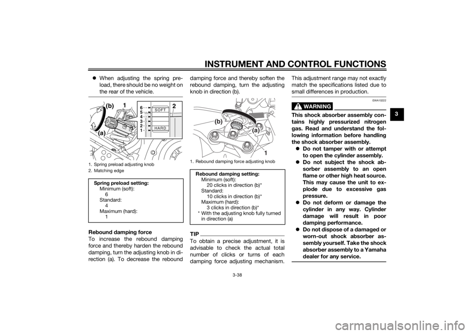
To increase the spring preload and
thereby harden the suspension, turn
the adjusting knob in direction (a). To
decrease the spring preload and there-
by soften the suspension, turn the ad-
justing knob in direction (b). NOTICE:
To avoi d dama gin g the a djustin g
kno b, d o not turn the a djustin g kno b
while sittin g on the vehicle.
[ECA20110]
TIP Align the appropriate mark on the
adjusting mechanism with the
matching edge.
1. Compression damping force adjusting
screwCompression dampin g settin g:
Minimum (soft): 13 click(s) in direction (b)*
Standard: 6 click(s) in direction (b)*
Maximum (hard):
1 click(s) in direction (b)*
* With the adjusting screw fully turned in direction (a)
1
(a)
(b)
U2BSE0E0.book Page 37 Tuesday, September 17, 2013 8:55 AM
Page 53 of 116
INSTRUMENT AND CONTROL FUNCTIONS
3-38
3
When adjusting the spring pre-
load, there should be no weight on
the rear of the vehicle.
Reboun d d ampin g force
To increase the rebound damping
force and thereby harden the rebound
damping, turn the adjusting knob in di-
rection (a). To decrease the rebound damping force and thereby soften the
rebound damping, turn the adjusting
knob in direction (b).
TIPTo obtain a precise adjustment, it is
advisable to check the actual total
number of clicks or turns of each
damping force adjusting mechanism. This adjustment range may not exactly
match the specifications listed due to
small differences in production.
WARNING
EWA10222
This shock a
bsor ber assem bly con-
tains hig hly pressurize d nitro gen
g as. Rea d an d un derstan d the fol-
lowin g information before han dlin g
the shock a bsor ber assem bly.
Do not tamper with or attempt
to open the cylind er assembly.
Do not su bject the shock a b-
sor ber assem bly to an open
flame or other hi gh heat source.
This may cause the unit to ex-
plo de due to excessive gas
pressure.
Do not deform or damag e the
cylin der in any way. Cylin der
d ama ge will result in poor
d ampin g performance.
Do not dispose of a damag ed or
worn-out shock a bsor ber as-
sem bly
yourself. Take the shock
a b sor ber assem bly to a Yamaha
d ealer for any service.
1. Spring preload adjusting knob
2. Matching edgeSprin g preloa d settin g:
Minimum (soft): 6
Standard:
4
Maximum (hard): 1
SOFT
HARD
1
(b)
(a)
6
5
4
3
2
1
2
1. Rebound damping force adjusting knob
Re boun d d ampin g settin g:
Minimum (soft): 20 clicks in direction (b)*
Standard: 10 clicks in direction (b)*
Maximum (hard):
3 clicks in direction (b)*
* With the adjusting knob fully turned in direction (a)
1
(b)
(a)
U2BSE0E0.book Page 38 Tuesday, September 17, 2013 8:55 AM
Page 54 of 116
INSTRUMENT AND CONTROL FUNCTIONS
3-39
3
EAU49702
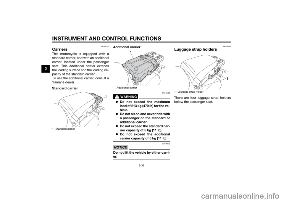
CarriersThis motorcycle is equipped with a
standard carrier, and with an additional
carrier, located under the passenger
seat. This additional carrier extends
the loading surface and the loading ca-
pacity of the standard carrier.
To use the additional carrier, consult a
Yamaha dealer.
Stan dar d carrier A
dditional carrier
WARNING
EWA15482
Do not exceed the maximum
loa d of 213 k g (470 l b) for the ve-
hicle.
Do not sit on an d never ri de with
a passen ger on the stan dar d or
a dditional carrier.
Do not exceed the standar d car-
rier capacity of 5 k g (11 l b).
Do not exceed the additional
carrier capacity of 5 kg (11 lb).NOTICE
ECA16822
Do not lift the vehicle by either carri-
er.
EAU49491
Lugga ge strap hol dersThere are four luggage strap holders
below the passenger seat.
1. Standard carrier
1
1. Additional carrier
1
1. Luggage strap holder
1
U2BSE0E0.book Page 39 Tuesday, September 17, 2013 8:55 AM
Page 62 of 116
OPERATION AND IMPORTANT RIDING POINTS
5-3
5
NOTICE
ECA10261
Even with the transmission in
the neutral position, do not
coast for lon g period s of time
with the en gine off, an d d o not
tow the motorcycle for lon g d is-
tances. The transmission is
properly lu bricated only when
the en gine is runnin g. Ina de-
quate lu brication may damag e
the transmission.
Always use the clutch while
chan gin g g ears to avoi d d am-
a g in g the en gine, transmission,
an d d rive train, which are not
d esi gne d to withstan d the
shock of force d shifting .
EAU16811
Tips for re ducin g fuel con-
sumptionFuel consumption depends largely on
your riding style. Consider the follow-
ing tips to reduce fuel consumption:
Shift up swiftly, and avoid high en-
gine speeds during acceleration.
Do not rev the engine while shift-
ing down, and avoid high engine
speeds with no load on the en-
gine.
Turn the engine off instead of let-
ting it idle for an extended length
of time (e.g., in traffic jams, at traf-
fic lights or at railroad crossings).
EAU16842
Engine break-inThere is never a more important period
in the life of your engine than the period
between 0 and 1600 km (1000 mi). For
this reason, you should read the fol-
lowing material carefully.
Since the engine is brand new, do not
put an excessive load on it for the first
1600 km (1000 mi). The various parts in
the engine wear and polish themselves
to the correct operating clearances.
During this period, prolonged full-throt-
tle operation or any condition that
might result in engine overheating
must be avoided.
EAU58990
0–1000 km (0–600 mi)
Avoid prolonged operation above 3900
r/min. NOTICE: After 1000 km (600
mi) of operation, the en gine oil an d
final gear oil must be chan ged , an d
the oil filter cartri dge or element re-
place d.
[ECA10333]
U2BSE0E0.book Page 3 Tuesday, September 17, 2013 8:55 AM