key YAMAHA XT1200Z 2015 User Guide
[x] Cancel search | Manufacturer: YAMAHA, Model Year: 2015, Model line: XT1200Z, Model: YAMAHA XT1200Z 2015Pages: 118, PDF Size: 3.13 MB
Page 31 of 118
INSTRUMENT AND CONTROL FUNCTIONS
3-16
3
The “L/100km” display shows the
amount of fuel necessary to travel
100 km.
For the UK only: The “MPG” dis-
play shows the distance that can
be traveled on 1.0 Imp.gal of fuel.
TIPIf traveling at speeds under 10 km/h (6
mi/h), “_ _._” will be displayed.NOTICE
ECA15474
If there is a malfunction, “– –.–” will
be continuously d isplayed. Have a
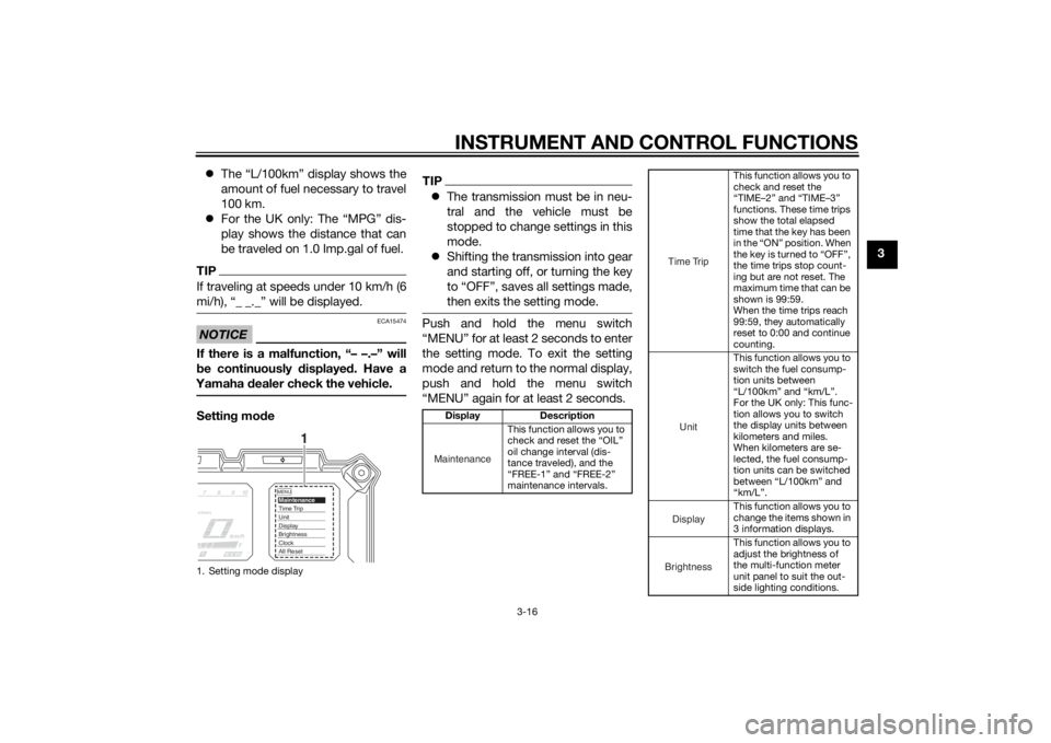
Yamaha dealer check the vehicle.Settin g mo de
TIP The transmission must be in neu-
tral and the vehicle must be
stopped to change settings in this
mode.
Shifting the transmission into gear
and starting off, or turning the key
to “OFF”, saves all settings made,
then exits the setting mode.Push and hold the menu switch
“MENU” for at least 2 seconds to enter
the setting mode. To exit the setting
mode and return to the normal display,
push and hold the menu switch
“MENU” again for at least 2 seconds.
1. Setting mode display
MENUMaintenanceTime TripUnitDisplayBrightnessClockAll Reset
1
Display Description
This function allows you to
check and reset the “OIL”
oil change interval (dis-
tance traveled), and the
“FREE-1” and “FREE-2”
maintenance intervals.Maintenance
This function allows you to
check and reset the
“TIME–2” and “TIME–3”
functions. These time trips
show the total elapsed
time that the key has been
in the “ON” position. When
the key is turned to “OFF”,
the time trips stop count-
ing but are not reset. The
maximum time that can be
shown is 99:59.
When the time trips reach
99:59, they automatically
reset to 0:00 and continue
counting.
This function allows you to
switch the fuel consump-
tion units between
“L/100km” and “km/L”.
For the UK only: This func-
tion allows you to switch
the display units between
kilometers and miles.
When kilometers are se-
lected, the fuel consump-
tion units can be switched
between “L/100km” and
“km/L”.
This function allows you to
change the items shown in
3 information displays.
This function allows you to
adjust the brightness of
the multi-function meter
unit panel to suit the out-
side lighting conditions.
Time TripUnitDisplayBrightness
U2BSE1E0.book Page 16 Thursday, July 31, 2014 4:31 PM
Page 36 of 118
INSTRUMENT AND CONTROL FUNCTIONS
3-21
3Self-d
iagnosis device
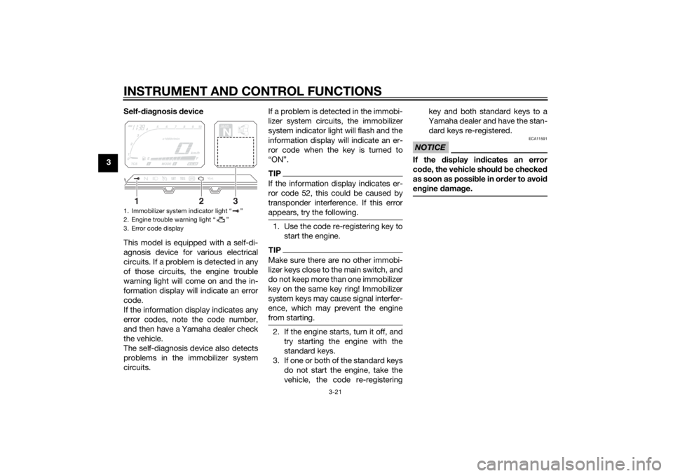
This model is equipped with a self-di-
agnosis device for various electrical
circuits. If a problem is detected in any
of those circuits, the engine trouble
warning light will come on and the in-
formation display will indicate an error
code.
If the information display indicates any
error codes, note the code number,
and then have a Yamaha dealer check
the vehicle.
The self-diagnosis device also detects
problems in the immobilizer system
circuits. If a problem is detected in the immobi-
lizer system circuits, the immobilizer
system indicator light will flash and the
information display will indicate an er-
ror code when the key is turned to
“ON”.
TIPIf the information display indicates er-
ror code 52, this could be caused by
transponder interference. If this error
appears, try the following.1. Use the code re-registering key to
start the engine.TIPMake sure there are no other immobi-
lizer keys close to the main switch, and
do not keep more than one immobilizer
key on the same key ring! Immobilizer
system keys may cause signal interfer-
ence, which may prevent the engine
from starting.2. If the engine starts, turn it off, andtry starting the engine with the
standard keys.
3. If one or both of the standard keys do not start the engine, take the
vehicle, the code re-registering key and both standard keys to a
Yamaha dealer and have the stan-
dard keys re-registered.
NOTICE
ECA11591
If the
display in dicates an error
co de, the vehicle shoul d b e checked
as soon as possi ble in or der to avoi d
en gine damag e.
1. Immobilizer system indicator light “ ”
2. Engine trouble warning light “ ”
3. Error code display
GEARN
25
A.TEMP ˚C
Lo
C.TEMP ˚C
0:00
TIME TRIP
1
2
3
U2BSE1E0.book Page 21 Thursday, July 31, 2014 4:31 PM
Page 38 of 118
INSTRUMENT AND CONTROL FUNCTIONS
3-23
3Ri
ght
EAU54201
Dimmer/Pass switch “ / /PASS”
Set this switch to “ ” for the high
beam and to “ ” for the low beam.
To flash the high beam, push the pass
side “PASS” of the switch while the
headlights are on low beam.
EAU12461
Turn si gnal switch “ / ”
To signal a right-hand turn, push this
switch to “ ”. To signal a left-hand
turn, push this switch to “ ”. When
released, the switch returns to the cen- ter position. To cancel the turn signal
lights, push the switch in after it has re-
turned to the center position.
EAU12501
Horn switch “ ”
Press this switch to sound the horn.
EAU54211
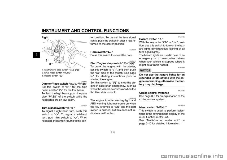
Start/En
gine stop switch “ / / ”
To crank the engine with the starter,
set this switch to “ ”, and then push
the “ ” side of the switch. See page
5-1 for starting instructions prior to
starting the engine.
Set this switch to “ ” to stop the en-
gine in case of an emergency, such as
when the vehicle overturns or when the
throttle cable is stuck.
EAU42342
The engine trouble warning light and
ABS warning light may come on when
the key is turned to “ON” and the start
switch is pushed, but this does not in-
dicate a malfunction.
EAU12735
Hazar d switch “ ”
With the key in the “ON” or “ ” posi-
tion, use this switch to turn on the haz-
ard lights (simultaneous flashing of all
turn signal lights).
The hazard lights are used in case of an
emergency or to warn other drivers
when your vehicle is stopped where it
might be a traffic hazard.NOTICE
ECA10062
Do not use the hazard lights for an
exten ded len gth of time with the en-
g ine not runnin g, otherwise the bat-
tery may dischar ge.
EAU12781
Cruise control switches
See page 3-6 for an explanation of the
cruise control system.
EAU59010
Menu switch “MENU”
This switch is used to perform selec-
tions in the setting mode display of the
multi-function meter unit.
See “Multi-function meter unit” on
page 3-10 for detailed information.
1. Start/Engine stop switch “ / / ”
2. Drive mode switch “MODE”
3. Hazard switch “ ”
MODESTOPRUNS TA R
T
3
2
1
U2BSE1E0.book Page 23 Thursday, July 31, 2014 4:31 PM
Page 42 of 118
INSTRUMENT AND CONTROL FUNCTIONS
3-27
3
TIPThe ABS performs a self-diagno-
sis test each time the vehicle first
starts off after the key is turned to
“ON” and the vehicle has traveled
at a speed of 10 km/h (6 mi/h) or
higher. During this test, a “click-
ing” noise can be heard from un-
der the seat, and if the brake lever
or brake pedal is even slightly ap-
plied, a vibration can be felt at the
lever and pedal, but these do not
indicate a malfunction.
This ABS has a test mode which
allows the owner to experience
the pulsation at the brake lever or
brake pedal when the ABS is op-
erating. However, special tools are
required, so please consult your
Yamaha dealer.NOTICE
ECA16831
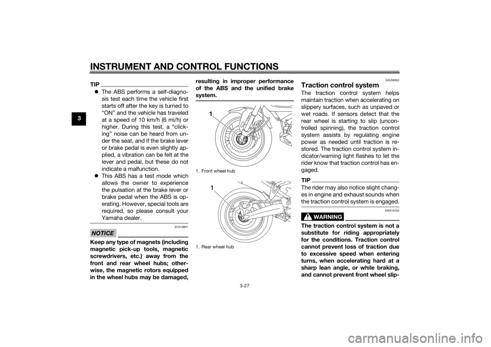
Keep any type of mag nets (includin g
ma gnetic pick-up tools, ma gnetic
screwd rivers, etc.) away from the
front an d rear wheel hu bs; other-
wise, the ma gnetic rotors equippe d
in the wheel hu bs may be damag ed , resultin
g in improper performance
of the ABS an d the unifie d b rake
system.
EAU58952
Traction control systemThe traction control system helps
maintain traction when accelerating on
slippery surfaces, such as unpaved or
wet roads. If sensors detect that the
rear wheel is starting to slip (uncon-
trolled spinning), the traction control
system assists by regulating engine
power as needed until traction is re-
stored. The traction control system in-
dicator/warning light flashes to let the
rider know that traction control has en-
gaged.TIPThe rider may also notice slight chang-
es in engine and exhaust sounds when
the traction control system is engaged.
WARNING
EWA15432
The traction control system is not a
su bstitute for rid ing appropriately
for the con ditions. Traction control
cannot prevent loss of traction due
to excessive speed when entering
turns, when acceleratin g har d at a
sharp lean an gle, or while brakin g,
an d cannot prevent front wheel slip-
1. Front wheel hub
1. Rear wheel hub
11
U2BSE1E0.book Page 27 Thursday, July 31, 2014 4:31 PM
Page 43 of 118
INSTRUMENT AND CONTROL FUNCTIONS
3-28
3
pin
g. As with any motorcycle, ap-
proach surfaces that may be
slippery with caution an d avoi d es-
pecially slippery surfaces.
There are three traction control system
modes: “TCS 1”: Default mode
“TCS 2”: Sporty mode
This mode decreases traction
control system assist, allowing the
rear wheel to spin more freely than
“TCS 1”.
“TCS OFF”: The traction control
system is turned off. The system
may also be automatically dis-
abled in some riding conditions
(see “Resetting” on page 3-28).
When the key is turned to “ON”, the
traction control system is enabled and
“TCS 1” is displayed in the multi-func-
tion meter.
The traction control system mode can
be changed only when the key is in the
“ON” position and the vehicle is not
moving.
TIPUse the mode “TCS OFF” to help free
the rear wheel if the motorcycle gets
stuck in mud, sand, or other soft sur-
faces.NOTICE
ECA16801
Use only the specifie d tires. (See
pa ge 6-18.) Usin g different sized
tires will prevent the traction control
system from controllin g tire rotation
accurately.Settin g the traction control system
WARNING
EWA15441
Be sure to stop the vehicle before
makin g any settin g chan ges to the
traction control system. Chan gin g
settin gs while ri din g can distract the
operator an d increase the risk of an
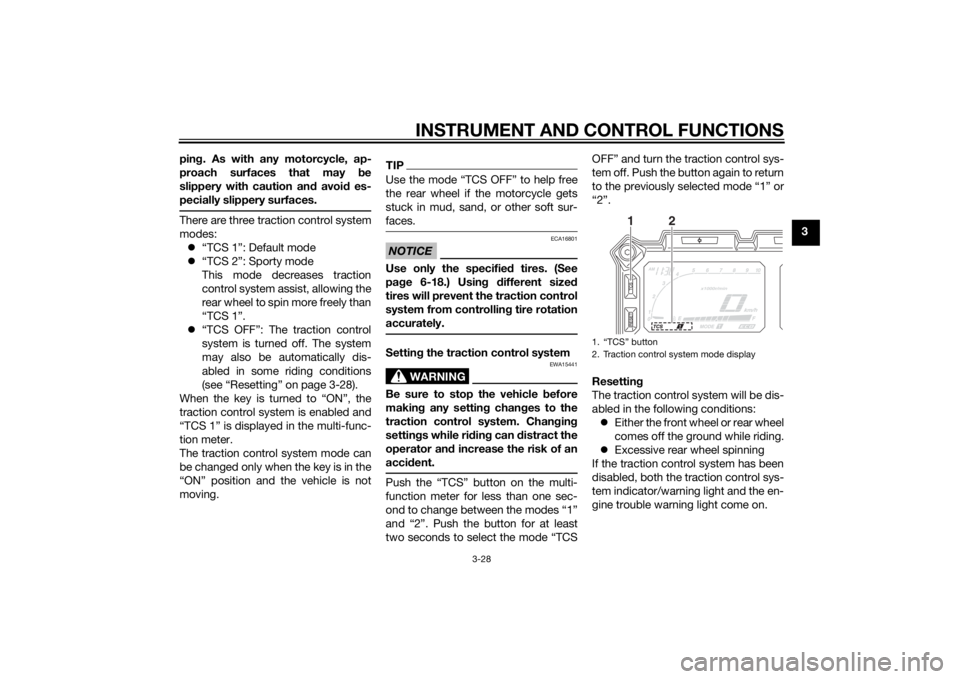
acci dent.Push the “TCS” button on the multi-
function meter for less than one sec-
ond to change between the modes “1”
and “2”. Push the button for at least
two seconds to select the mode “TCS OFF” and turn the traction control sys-
tem off. Push the button again to return
to the previously selected mode “1” or
“2”.
Resettin
g
The traction control system will be dis-
abled in the following conditions: Either the front wheel or rear wheel
comes off the ground while riding.
Excessive rear wheel spinning
If the traction control system has been
disabled, both the traction control sys-
tem indicator/warning light and the en-
gine trouble warning light come on.
1. “TCS” button
2. Traction control system mode display
1
2
U2BSE1E0.book Page 28 Thursday, July 31, 2014 4:31 PM
Page 44 of 118
INSTRUMENT AND CONTROL FUNCTIONS
3-29
3To reset the traction control system:
Turn the key to “OFF”. Wait at least one
second, then turn the key back to
“ON”. The traction control system indi-
cator/warning light should go off and
the system will be enabled. The engine
trouble warning light should go off after
the motorcycle reaches at least 20
km/h (12 mi/h). If the traction control
system indicator/warning light or the
engine trouble warning light remains
on after resetting, the motorcycle may
still be ridden; however, have a
Yamaha dealer check the motorcycle as soon as possible.
EAU13075
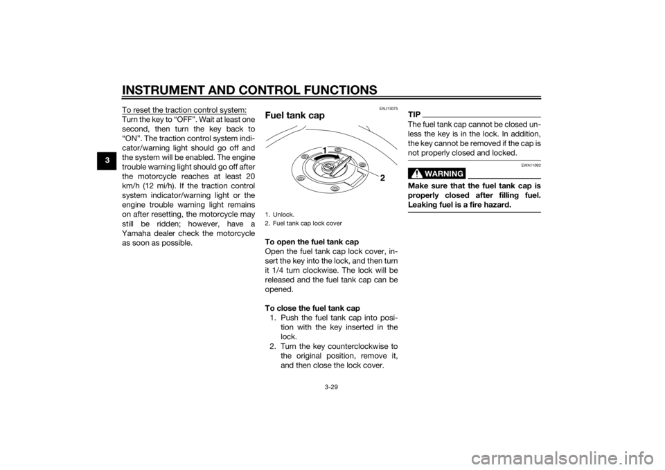
Fuel tank capTo open the fuel tank cap
Open the fuel tank cap lock cover, in-
sert the key into the lock, and then turn
it 1/4 turn clockwise. The lock will be
released and the fuel tank cap can be
opened.
To close the fuel tank cap 1. Push the fuel tank cap into posi- tion with the key inserted in the
lock.
2. Turn the key counterclockwise to the original position, remove it,
and then close the lock cover.
TIPThe fuel tank cap cannot be closed un-
less the key is in the lock. In addition,
the key cannot be removed if the cap is
not properly closed and locked.
WARNING
EWA11092
Make sure that the fuel tank cap is
properly close d after fillin g fuel.
Leakin g fuel is a fire hazar d.
1. Unlock.
2. Fuel tank cap lock cover
2
1
U2BSE1E0.book Page 29 Thursday, July 31, 2014 4:31 PM
Page 47 of 118
INSTRUMENT AND CONTROL FUNCTIONS
3-32
3
NOTICE
ECA10702
Use only unleaded g asoline. The use
of lead ed g asoline will cause unre-
paira ble damag e to the catalytic
converter.
EAU49444
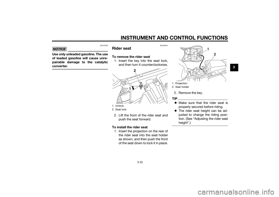
Ri der seatTo remove the ri der seat
1. Insert the key into the seat lock, and then turn it counterclockwise.
2. Lift the front of the rider seat and push the seat forward.
To install the ri der seat
1. Insert the projection on the rear of the rider seat into the seat holder
as shown, and then push the front
of the seat down to lock it in place. 2. Remove the key.
TIP
Make sure that the rider seat is
properly secured before riding.
The rider seat height can be ad-
justed to change the riding posi-
tion. (See “Adjusting the rider seat
height”.)
1. Unlock.
2. Seat lock
2
1
1. Projection
2. Seat holder
1
2
U2BSE1E0.book Page 32 Thursday, July 31, 2014 4:31 PM
Page 56 of 118
INSTRUMENT AND CONTROL FUNCTIONS
3-41
3
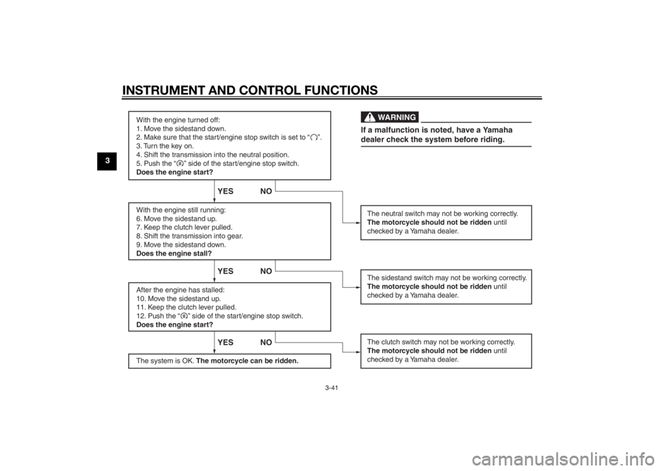
With the engine turned off:
1. Move the sidestand down.
2. Make sure that the start/engine stop switch is set to “ ”.
3. Turn the key on.
4. Shift the transmission into the neutral position.
5. Push the “ ” side of the start/engine stop switch.
Does the engine start?
With the engine still running:
6. Move the sidestand up.
7. Keep the clutch lever pulled.
8. Shift the transmission into gear.
9. Move the sidestand down.
Does the engine stall?
After the engine has stalled:
10. Move the sidestand up.
11. Keep the clutch lever pulled.
12. Push the “ ” side of the start/engine stop switch.
Does the engine start?
The system is OK. The motorcycle can be ridden.
YES NO YES NO YES NO
The neutral switch may not be working correctly.
The motorcycle should not be ridden until
checked by a Yamaha dealer.
The clutch switch may not be working correctly.
The motorcycle should not be ridden until
checked by a Yamaha dealer.The sidestand switch may not be working correctly.
The motorcycle should not be ridden until
checked by a Yamaha dealer.If a malfunction is noted, have a Yamaha
dealer check the system before riding.
WA R N I N G
U2BSE1E0.book Page 41 Thursday, July 31, 2014 4:31 PM
Page 57 of 118
INSTRUMENT AND CONTROL FUNCTIONS
3-42
3
EAU49453
Auxiliary DC jack
WARNING
EWA14361
To prevent electrical shock or short-
circuiting, make sure that the cap is
installe d when the auxiliary DC jack
is not bein g use d.NOTICE
ECA15432
The accessory connected to the
auxiliary DC jack shoul d not b e used
with the en gine turne d off, an d the
loa d must never excee d 30 W (2.5 A),
otherwise the fuse may blow or the
b attery may dischar ge.This vehicle is equipped with an auxil-
iary DC jack.
A 12-V accessory connected to the
auxiliary DC jack can be used when the
key is in the “ON” position and should
only be used when the engine is run-
ning.
To use the auxiliary DC jack
1. Turn the key to “OFF”.
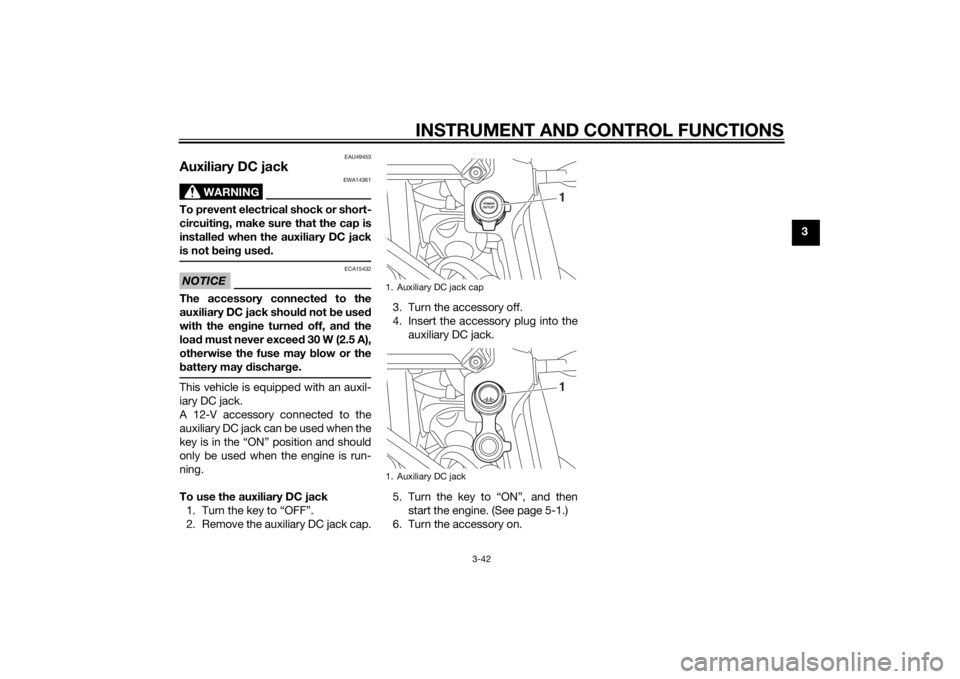
2. Remove the auxiliary DC jack cap. 3. Turn the accessory off.
4. Insert the accessory plug into the
auxiliary DC jack.
5. Turn the key to “ON”, and then start the engine. (See page 5-1.)
6. Turn the accessory on.
1. Auxiliary DC jack cap
1. Auxiliary DC jack
11
U2BSE1E0.book Page 42 Thursday, July 31, 2014 4:31 PM
Page 60 of 118
OPERATION AND IMPORTANT RIDING POINTS
5-1
5
EAU15952
Read the Owner’s Manual carefully to
become familiar with all controls. If
there is a control or function you do not
understand, ask your Yamaha dealer.
WARNING
EWA10272
Failure to familiarize yourself with
the controls can lead to loss of con-
trol, which coul d cause an acci dent
or injury.
EAU48712
TIPThis model is equipped with: a lean angle sensor to stop the en-
gine in case of a turnover. In this
case, the display will indicate error
code 30, but this is not a malfunc-
tion. Turn the key to “OFF” and
then to “ON” to clear the error
code. Failing to do so will prevent
the engine from starting even
though the engine will crank when
pushing the start switch.
an engine auto-stop system. The
engine stops automatically if left
idling for 20 minutes. If the engine
stops, simply push the start
switch to restart the engine.
EAU54171
Startin g the en gineIn order for the ignition circuit cut-off
system to enable starting, one of the
following conditions must be met:
The transmission is in the neutral
position.
The transmission is in gear with
the clutch lever pulled and the
sidestand up.
See page 3-40 for more informa-
tion.
1. Turn the key to “ON” and make sure that the start/engine stop
switch is set to “ ”.
The following warning lights and
indicator lights should come on for
a few seconds, then go off. Oil level warning light
Engine trouble warning light
Traction control system indi-
cator/warning light
Cruise control indicator lights
Immobilizer system indicator
light
U2BSE1E0.book Page 1 Thursday, July 31, 2014 4:31 PM