parking brake YAMAHA XT1200Z 2017 Owners Manual
[x] Cancel search | Manufacturer: YAMAHA, Model Year: 2017, Model line: XT1200Z, Model: YAMAHA XT1200Z 2017Pages: 120, PDF Size: 3.32 MB
Page 5 of 120

Table of contents
Safety information ............................1-1
Description ........................................2-1
Left view ..........................................2-1
Right view........................................2-2
Controls and instruments ................2-3
Instrument an d control functions ....3-1
Immobilizer system .........................3-1
Main switch/steering lock ...............3-2
Indicator lights and warning lights ............................................3-4
Cruise control system .....................3-6
Multi-function meter unit .................3-9
D-mode (drive mode) ....................3-20
Handlebar switches.......................3-20
Clutch lever ...................................3-22
Shift pedal .....................................3-22
Brake lever ....................................3-23
Brake pedal ...................................3-24
ABS ...............................................3-24
Traction control system.................3-25
Fuel tank cap.................................3-27
Fuel................................................3-28
Fuel tank overflow hose ................3-29
Catalytic converter ........................3-30
Rider seat ......................................3-30
Adjusting the rider seat height ......3-31
Windshield.....................................3-33
Adjusting the front fork..................3-34
Adjusting the shock absorber assembly....................................3-36
Carriers..........................................3-38
Luggage strap holders ..................3-39
Sidestand ......................................3-39
Ignition circuit cut-off system........3-40
Auxiliary DC jack ...........................3-42
For your safety – pre-operation
checks ...............................................4-1
Operation an d important ri din g
points .................................................5-1
Starting the engine ..........................5-2
Shifting ............................................5-3 Tips for reducing fuel
consumption................................ 5-4
Engine break-in ............................... 5-4
Parking ............................................ 5-5
Perio dic maintenance an d
a d justment ........................................ 6-1
Owner’s tool kit ............................... 6-2
Periodic maintenance chart for the
emission control system.............. 6-3
General maintenance and
lubrication chart........................... 6-4
Removing and installing cowlings ...................................... 6-7
Checking the spark plugs ............... 6-9
Canister......................................... 6-10
Engine oil and oil filter cartridge ... 6-10
Final gear oil.................................. 6-14
Coolant ......................................... 6-16
Air filter element ............................ 6-17
Checking the engine idling speed......................................... 6-18
Checking the throttle grip free
play ............................................ 6-18
Valve clearance ............................. 6-19
Tires .............................................. 6-19
Spoke wheels ............................... 6-22
Clutch lever ................................... 6-22
Checking the brake lever free play ............................................ 6-23
Brake light switches ...................... 6-23
Checking the front and rear brake pads................................. 6-24
Checking the brake fluid level....... 6-25
Changing the brake and clutch fluids .......................................... 6-26
Checking and lubricating the throttle grip and cable ............... 6-26
Checking and lubricating the brake and shift pedals ............... 6-27
Checking and lubricating the
brake and clutch levers ............. 6-27
Checking and lubricating the sidestand ................................... 6-28
Lubricating the swingarm pivots... 6-28
Checking the front fork ................. 6-29
UBP8E0E0.book Page 1 Thursday, December 8, 2016 7:25 PM
Page 37 of 120

Instrument and control functions
3-23
3
EAU49518
Brake lever
The brake lever is located on the right
side of the handlebar. To apply the
front brake, pull the lever toward the
throttle grip.
This model is equipped with a unified
brake system.
When pulling the brake lever, the front
brake and a portion of the rear brake
are applied. For full braking perfor-
mance, apply both the brake lever and
the brake pedal simultaneously.
The unified brake system is monitored
by an ECU, which disables unified
braking and resumes conventional
braking if a malfunction occurs.
TIP
Resistance and vibration may be
felt in the brake pedal while the
front brake is being applied and
the unified brake system is en-
abled, but this does not indicate a
malfunction.
The unified brake system does not
function until the vehicle starts
moving.
After coming to a stop while ap-
plying the brake lever, the unified
brake system is still enabled. As
further squeezing of the brake le-
ver will not increase the braking
power of the rear brake, apply the
rear brake should further braking
power be necessary (such as
when parking on a slope).
The unified brake system disables
after the brake lever is released.
The brake system then reverts to
the conventional type. When the vehicle starts moving,
the unified brake system is re-en-
abled.
The unified brake system does not
function when the brake pedal is
applied alone or before the brake
lever is applied.
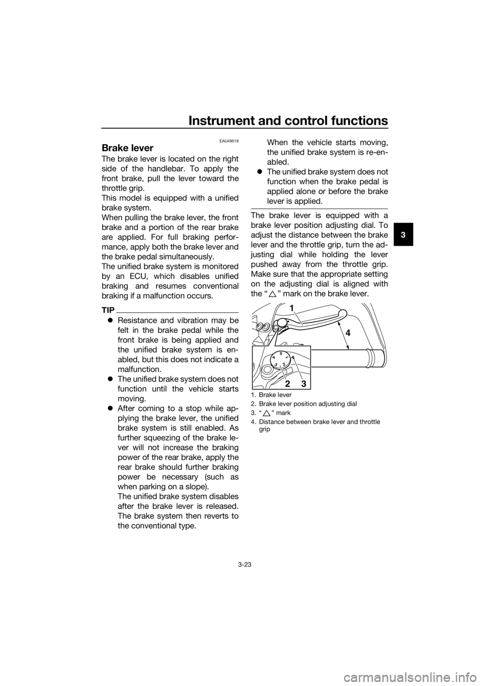
The brake lever is equipped with a
brake lever position adjusting dial. To
adjust the distance between the brake
lever and the throttle grip, turn the ad-
justing dial while holding the lever
pushed away from the throttle grip.
Make sure that the appropriate setting
on the adjusting dial is aligned with
the “ ” mark on the brake lever.
1. Brake lever
2. Brake lever position adjusting dial
3. “ ” mark
4. Distance between brake lever and throttle
grip
54
32
1
1
4
32
UBP8E0E0.book Page 23 Thursday, December 8, 2016 7:25 PM
Page 95 of 120

Periodic maintenance an d a djustment
6-32
6
EAU58963
Replacin g the fuses
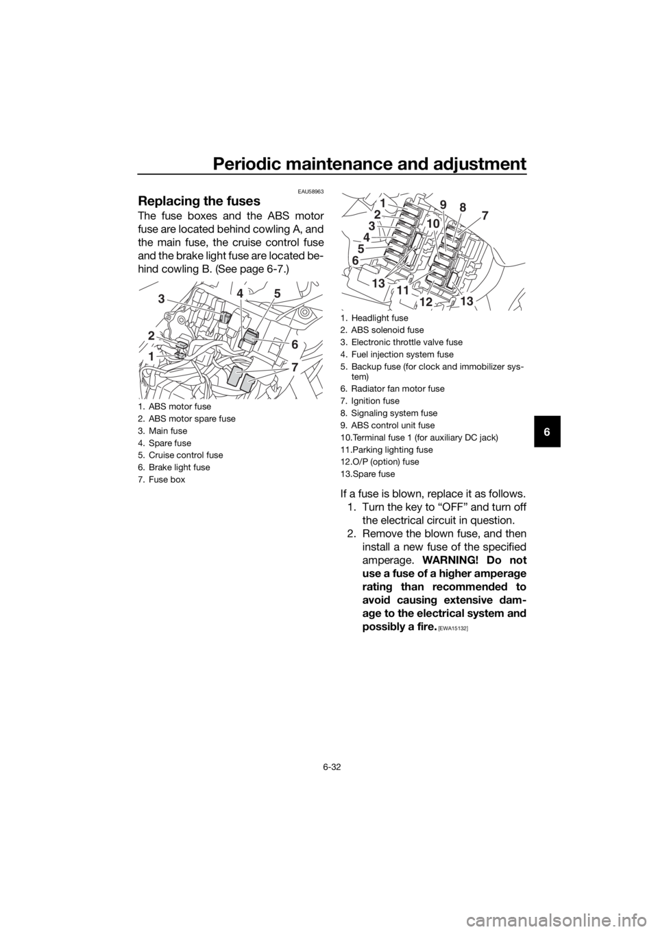
The fuse boxes and the ABS motor
fuse are located behind cowling A, and
the main fuse, the cruise control fuse
and the brake light fuse are located be-
hind cowling B. (See page 6-7.)
If a fuse is blown, replace it as follows.1. Turn the key to “OFF” and turn off the electrical circuit in question.
2. Remove the blown fuse, and then install a new fuse of the specified
amperage. WARNING! Do not
use a fuse of a hi gher ampera ge
ratin g than recommen ded to
avoi d causin g extensive dam-
a g e to the electrical system an d
possi bly a fire.
[EWA15132]
1. ABS motor fuse
2. ABS motor spare fuse
3. Main fuse
4. Spare fuse
5. Cruise control fuse
6. Brake light fuse
7. Fuse box
1
2
354
6
7
1. Headlight fuse
2. ABS solenoid fuse
3. Electronic throttle valve fuse
4. Fuel injection system fuse
5. Backup fuse (for clock and immobilizer sys-
tem)
6. Radiator fan motor fuse
7. Ignition fuse
8. Signaling system fuse
9. ABS control unit fuse
10.Terminal fuse 1 (for auxiliary DC jack)
11.Parking lighting fuse
12.O/P (option) fuse
13.Spare fuse
1
3
4
5
6
2789
10
1311
1213
UBP8E0E0.book Page 32 Thursday, December 8, 2016 7:25 PM
Page 96 of 120

Periodic maintenance an d a djustment
6-33
6
3. Turn the key to “ON” and turn onthe electrical circuit in question to
check if the device operates.
4. If the fuse immediately blows again, have a Yamaha dealer
check the electrical system.
EAU39014
Replacin g a head light bul b
This model is equipped with halogen
bulb headlights. If a headlight bulb
burns out, replace it as follows.
NOTICE
ECA10651
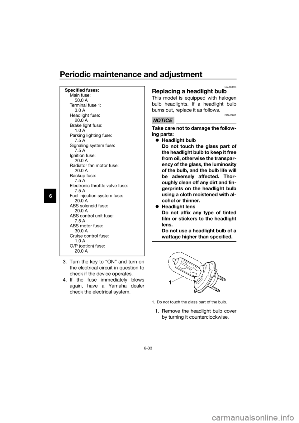
Take care not to d amage the follow-
in g parts:
Hea dlig ht bul b
Do not touch the glass part of
the hea dlig ht bul b to keep it free
from oil, otherwise the transpar-
ency of the glass, the luminosity
of the b ulb, an d the b ulb life will
b e ad versely affected . Thor-
ou ghly clean off any d irt and fin-
g erprints on the hea dlig ht bul b
usin g a cloth moistene d with al-
cohol or thinner.
Hea dlig ht lens
Do not affix any type of tinted
film or stickers to the head light
lens.
Do not use a hea dlig ht bul b of a
watta ge hi gher than specifie d.
1. Remove the headlight bulb cover
by turning it counterclockwise.
Specifie d fuses:
Main fuse: 50.0 A
Te r m i n a l f u s e 1 :
3.0 A
Headlight fuse: 20.0 A
Brake light fuse: 1.0 A
Parking lighting fuse:
7.5 A
Signaling system fuse: 7.5 A
Ignition fuse: 20.0 A
Radiator fan motor fuse:
20.0 A
Backup fuse: 7.5 A
Electronic throttle valve fuse: 7.5 A
Fuel injection system fuse:
20.0 A
ABS solenoid fuse: 20.0 A
ABS control unit fuse: 7.5 A
ABS motor fuse:
30.0 A
Cruise control fuse: 1.0 A
O/P (option) fuse: 20.0 A
1. Do not touch the glass part of the bulb.
UBP8E0E0.book Page 33 Thursday, December 8, 2016 7:25 PM
Page 112 of 120

Specifications
8-3
8
Battery:
Model:YTZ12S
Voltage, capacity:
12 V, 11.0 Ah (10 HR)
Hea dlig ht:
Bulb type:
Halogen bulb
Bul b watta ge:
Headlight:
H7, 55.0 W
Brake/tail light: LED
Front turn signal light:
LED
Rear turn signal light:
LED
Auxiliary light: 5.0 W
License plate light: 5.0 W
Meter lighting:
LED
Neutral indicator light: LED
High beam indicator light: LED
Oil level warning light:
LED
Turn signal indicator light: LED
Engine trouble warning light: LED
ABS warning light:
LED
Cruise control “SET” indicator light: LED
Cruise control “ON” indicator light: LED
Immobilizer system indicator light:
LED
Traction control system indicator/warning
light:
LED
Fuse(s):
Main fuse:50.0 A
Terminal fuse 1:
3.0 A Headlight fuse:
20.0 A
Brake light fuse: 1.0 A
Signaling system fuse:
7.5 A
Ignition fuse: 20.0 A
Parking lighting fuse: 7.5 A
Radiator fan motor fuse:
20.0 A
Fuel injection system fuse: 20.0 A
ABS control unit fuse: 7.5 A
ABS motor fuse: 30.0 A
ABS solenoid fuse:
20.0 A
Cruise control fuse: 1.0 A
Backup fuse: 7.5 A
Electronic throttle valve fuse:
7.5 A
O/P (option) fuse: 20.0 A
UBP8E0E0.book Page 3 Thursday, December 8, 2016 7:25 PM
Page 116 of 120

10-1
10
Index
A
ABS ....................................................... 3-24
ABS warning light ................................... 3-5
Air filter element .................................... 6-17
Auxiliary DC jack ................................... 3-42
Auxiliary light bulb, replacing ................ 6-35
B
Battery .................................................. 6-30
Brake and clutch fluids, changing ........ 6-26
Brake and clutch levers, checking and
lubricating ........................................... 6-27
Brake and shift pedals, checking and
lubricating ........................................... 6-27
Brake fluid level, checking .................... 6-25
Brake lever ............................................ 3-23
Brake lever free play, checking............. 6-23
Brake light switches.............................. 6-23
Brake pedal........................................... 3-24
C
Canister................................................. 6-10
Care ........................................................ 7-1
Carriers ................................................. 3-38
Catalytic converter ................................ 3-30
Clutch lever ................................. 3-22, 6-22
Coolant ................................................. 6-16
Cowlings, removing and installing .......... 6-7
Cruise control indicator lights ................. 3-4
Cruise control switches ........................ 3-21
Cruise control system ............................. 3-6
D
Data recording, vehicle ........................... 9-3
Diagnostic connector.............................. 9-2
Dimmer/Pass switch ............................. 3-20
D-mode (drive mode) ............................ 3-20
E
Engine break-in....................................... 5-4
Engine idling speed, checking .............. 6-18
Engine oil and oil filter cartridge ........... 6-10
Engine serial number .............................. 9-1
Engine trouble warning light ................... 3-5
F
Final gear oil.......................................... 6-14
Front and rear brake pads, checking.... 6-24
Front fork, adjusting.............................. 3-34
Front fork, checking .............................. 6-29
Fuel ....................................................... 3-28
Fuel consumption, tips for reducing ....... 5-4
Fuel tank cap ........................................ 3-27
Fuel tank overflow hose ........................ 3-29
Fuses, replacing.................................... 6-32
H
Handlebar switches .............................. 3-20
Hazard switch....................................... 3-21
Headlight bulb, replacing ..................... 6-33
High beam indicator light ....................... 3-4
Horn switch .......................................... 3-21
I
Identification numbers ............................ 9-1
Ignition circuit cut-off system............... 3-40
Immobilizer system ................................ 3-1
Immobilizer system indicator light.......... 3-5
Indicator lights and warning lights ......... 3-4
L
License plate light bulb, replacing........ 6-38
Luggage strap holders ......................... 3-39
M
Main switch/steering lock....................... 3-2
Maintenance and lubrication, periodic ... 6-4
Maintenance, emission control system.................................................. 6-3
Matte color, caution ............................... 7-1
Menu switch ......................................... 3-21
Model label ............................................. 9-1
Multi-function meter unit ........................ 3-9
N
Neutral indicator light ............................. 3-4
O
Oil level warning light ............................. 3-4
P
Parking ................................................... 5-5
Part locations ......................................... 2-1
R
Rider seat ............................................. 3-30
Rider seat height, adjusting.................. 3-31
S
Safety information .................................. 1-1
Select switch ........................................ 3-21
Shifting ................................................... 5-3
Shift pedal ............................................ 3-22
Shock absorber assembly, adjusting ... 3-36
Sidestand ............................................. 3-39
Sidestand, checking and lubricating .... 6-28
Spark plugs, checking ............................ 6-9
Specifications ......................................... 8-1
Starting the engine ................................. 5-2
Steering, checking................................ 6-29
Stop/Run/Start switch .......................... 3-21
Storage ................................................... 7-4
Supporting the motorcycle................... 6-39
Swingarm pivots, lubricating ................ 6-28
UBP8E0E0.book Page 1 Thursday, December 8, 2016 7:25 PM