traction control YAMAHA XT1200Z 2019 Owners Manual
[x] Cancel search | Manufacturer: YAMAHA, Model Year: 2019, Model line: XT1200Z, Model: YAMAHA XT1200Z 2019Pages: 118, PDF Size: 3.8 MB
Page 5 of 118

Table of contents
Safety information ............................1-1
Description ........................................2-1
Left view ..........................................2-1
Right view........................................2-2
Controls and instruments ................2-3
Instrument an d control functions ....3-1
Immobilizer system .........................3-1
Main switch/steering lock ...............3-2
Indicator lights and warning lights ............................................3-3
Cruise control system .....................3-6
Multi-function meter unit .................3-9
D-mode (drive mode) ....................3-19
Handlebar switches.......................3-20
Clutch lever ...................................3-22
Shift pedal .....................................3-22
Brake lever ....................................3-23
Brake pedal ...................................3-24
ABS ...............................................3-24
Traction control system.................3-25
Fuel tank cap.................................3-27
Fuel................................................3-28
Fuel tank overflow hose ................3-29
Catalytic converter ........................3-30
Rider seat ......................................3-30
Adjusting the rider seat height ......3-31
Windshield.....................................3-33
Adjusting the front fork..................3-34
Adjusting the shock absorber assembly....................................3-36
Carriers..........................................3-37
Luggage strap holders ..................3-38
Auxiliary DC jack ...........................3-39
Sidestand ......................................3-40
Ignition circuit cut-off system........3-40
For your safety – pre-operation
checks ...............................................4-1
Operation an d important ri din g
points .................................................5-1
Starting the engine ..........................5-2
Shifting ............................................5-3 Tips for reducing fuel
consumption................................ 5-4
Engine break-in ............................... 5-5
Parking ............................................ 5-6
Perio dic maintenance an d
a d justment ........................................ 6-1
Tool kit ............................................ 6-2
Periodic maintenance charts .......... 6-3
Periodic maintenance chart for the emission control system.............. 6-3
General maintenance and lubrication chart........................... 6-4
Removing and installing
cowlings ...................................... 6-7
Checking the spark plugs ............... 6-9
Canister......................................... 6-10
Engine oil ...................................... 6-10
Why Yamalube .............................. 6-13
Final gear oil.................................. 6-14
Coolant ......................................... 6-16
Air filter element ............................ 6-17
Checking the engine idling speed......................................... 6-18
Checking the throttle grip free play ............................................ 6-18
Valve clearance ............................. 6-19
Tires .............................................. 6-19
Spoke wheels ............................... 6-22
Clutch lever ................................... 6-22
Checking the brake lever free play ............................................ 6-23
Brake light switches ...................... 6-23
Checking the front and rear brake pads................................. 6-24
Checking the brake fluid level....... 6-25
Changing the brake and clutch fluids .......................................... 6-26
Checking and lubricating the throttle grip and cable ............... 6-26
Checking and lubricating the
brake and shift pedals ............... 6-27
Checking and lubricating the brake and clutch levers ............. 6-27
Checking and lubricating the
sidestand ................................... 6-28
UBP8E1E0.book Page 1 Friday, September 14, 2018 11:35 AM
Page 17 of 118
Instrument and control functions
3-3
3
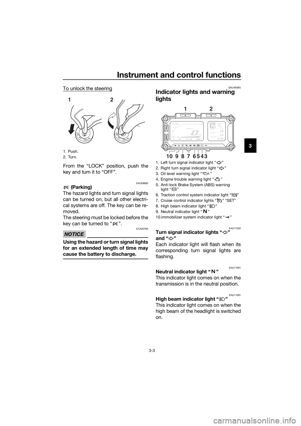
To unlock the steering
From the “LOCK” position, push the
key and turn it to “OFF”.
EAU59680 (Parkin
g)
The hazard lights and turn signal lights
can be turned on, but all other electri-
cal systems are off. The key can be re-
moved.
The steering must be locked before the
key can be turned to “ ”.
NOTICE
ECA20760
Usin g the hazar d o r t u r n s i gnal li ghts
for an exten ded len gth of time may
cause the battery to d ischarge.
EAU4939G
In dicator li ghts an d warnin g
lig hts
EAU11032Turn si gnal in dicator li ghts “ ”
an d“”
Each indicator light will flash when its
corresponding turn signal lights are
flashing.
EAU11061Neutral in dicator li ght “ ”
This indicator light comes on when the
transmission is in the neutral position.
EAU11081Hi gh beam in dicator li ght “ ”
This indicator light comes on when the
high beam of the headlight is switched
on.
1. Push.
2. Turn.
12
1. Left turn signal indicator light “ ”
2. Right turn signal indicator light “ ”
3. Oil level warning light “ ”
4. Engine trouble warning light “ ”
5. Anti-lock Brake System (ABS) warning light “ ”
6. Traction control system indicator light “ ”
7. Cruise control indicator lights “ ” “SET”
8. High beam indicator light “ ”
9. Neutral indicator light “ ”
10.Immobilizer system indicator light “ ”
GEARN25A.TEMP ˚C
LoC.TEMP˚C
0:00TIME TRIP
345687910
12
ABS
UBP8E1E0.book Page 3 Friday, September 14, 2018 11:35 AM
Page 19 of 118

Instrument and control functions
3-5
3
b
rakin g. Have a Yamaha d ealer
check the brake system an d electri-
cal circuits as soon as possi ble.
EAU74082Traction control system in dicator
li g ht “ ”
This indicator light will flash when trac-
tion control has engaged.
If the traction control system is turned
off, this indicator light will come on.
TIP
When the vehicle is turned on, the light
should come on for a few seconds and
then go off. If the light does not come
on, or if the light remains on, have a
Yamaha dealer check the vehicle.
EAU73120Immo bilizer system in dicator
li g ht “ ”
When the key is turned to “OFF” and
30 seconds have passed, the indicator
light will flash steadily to indicate the
immobilizer system is enabled. After 24
hours have passed, the indicator light
will stop flashing, however the immobi-
lizer system is still enabled.
The electrical circuit of the indicator
light can be checked by turning the key
to “ON”. The indicator light should
come on for a few seconds, and then
go off.
If the indicator light does not come on
initially when the key is turned to “ON”,
if the indicator light remains on, or if the
indicator light flashes in a pattern (if a
problem is detected in the immobilizer
system, the immobilizer system indica-
tor light will flash in a pattern), have a
Yamaha dealer check the vehicle.
TIP
If the immobilizer system indicator light
flashes in the pattern, slowly 5 times
then quickly 2 times, this could be
caused by transponder interference. If
this occurs, try the following.
1. Make sure there are no other im- mobilizer keys close to the main
switch. Other immobilizer system
keys may cause signal interfer-
ence and prevent the engine from
starting.
2. Use the code re-registering key to start the engine.
3. If the engine starts, turn it off, and try starting the engine with the
standard keys.
4. If one or both of the standard keys do not start the engine, take the
vehicle and all 3 keys to a Yamaha
dealer to have the standard keys
re-registered.
UBP8E1E0.book Page 5 Friday, September 14, 2018 11:35 AM
Page 22 of 118

Instrument and control functions
3-8
3
WARNING
EWA16351
It is d angerous to use the resume
function when the previously set
cruisin g speed is too hi gh for current
con ditions.
TIP
Pushing the power switch while the
system is operating will turn the system
off completely and erase the previously
set cruising speed. You will not be able
to use the resume function until a new
cruising speed has been set.
Automatic deactivation of the cruise
control system
The cruise control system for this mod-
el is electronically controlled and is
linked with the other control systems.
The cruise control system will auto-
matically become deactivated under
the following conditions:
The cruise control system is not
able to maintain the set cruising
speed.
Wheel slip or wheel spin is detect-
ed. (If the traction control system
has not been turned off, the trac-
tion control system will work.)
The start/engine stop switch is set
to the “ ” position.
The engine stalls.
The sidestand is lowered.
When traveling with a set cruising
speed, if the cruise control system is
deactivated under the above condi-
tions, the “ ” indicator light will go off
and the “SET” indicator light will flash
for 4 seconds, and then go off. When not traveling with a set cruising
speed, if the start/engine stop switch is
set to the “ ” position, the engine
stalls, or the sidestand is lowered, then
the “ ” indicator light will go off (the
“SET” indicator light will not flash).
If the cruise control system is automat-
ically deactivated, please stop and
confirm that your vehicle is in good op-
erating condition.
Before using the cruise control system
again, activate it using the power
switch.
TIP
In some cases, the cruise control sys-
tem may not be able to maintain the set
cruising speed when the vehicle is
traveling uphill or downhill.
When the vehicle is traveling up-
hill, the actual traveling speed may
become lower than the set cruis-
ing speed. If this occurs, acceler-
ate to the desired traveling speed
using the throttle.
When the vehicle is traveling
downhill, the actual traveling
speed may become higher than
the set cruising speed. If this oc-
curs, the setting switch cannot be
used to adjust the set cruising
speed. To reduce the traveling
speed, apply the brakes. When
the brakes are applied, the cruise
control system will become deac-
tivated.
UBP8E1E0.book Page 8 Friday, September 14, 2018 11:35 AM
Page 23 of 118
Instrument and control functions
3-9
3
EAU58937
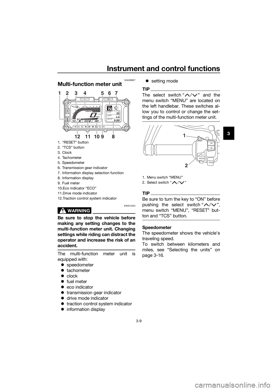
Multi-function meter unit
WARNING
EWA12423
Be sure to stop the vehicle before
makin g any settin g chan ges to the
multi-function meter unit. Chang ing
settin gs while ri din g can d istract the
operator an d increase the risk of an
acci dent.
The multi-function meter unit is
equipped with:
speedometer
tachometer
clock
fuel meter
eco indicator
transmission gear indicator
drive mode indicator
traction control system indicator
information display
setting mode
TIP
The select switch “ / ” and the
menu switch “MENU” are located on
the left handlebar. These switches al-
low you to control or change the set-
tings of the multi-function meter unit.
TIP
Be sure to turn the key to “ON” before
pushing the select switch “ / ”,
menu switch “MENU”, “RESET” but-
ton and “TCS” button.
Speed ometer
The speedometer shows the vehicle’s
traveling speed.
To switch between kilometers and
miles, see “Selecting the units” on
page 3-16.
1. “RESET” button
2. “TCS” button
3. Clock
4. Tachometer
5. Speedometer
6. Transmission gear indicator
7. Information display selection function
8. Information display
9. Fuel meter
10.Eco indicator “ECO”
11.Drive mode indicator
12.Traction control system indicator
GEARN25A.TEMP ˚C
LoC.TEMP˚C
0:00TIME TRIP
89101112
12 3 4 56
7
1. Menu switch “MENU”
2. Select switch “ / ”
1
2
UBP8E1E0.book Page 9 Friday, September 14, 2018 11:35 AM
Page 25 of 118
Instrument and control functions
3-11
3
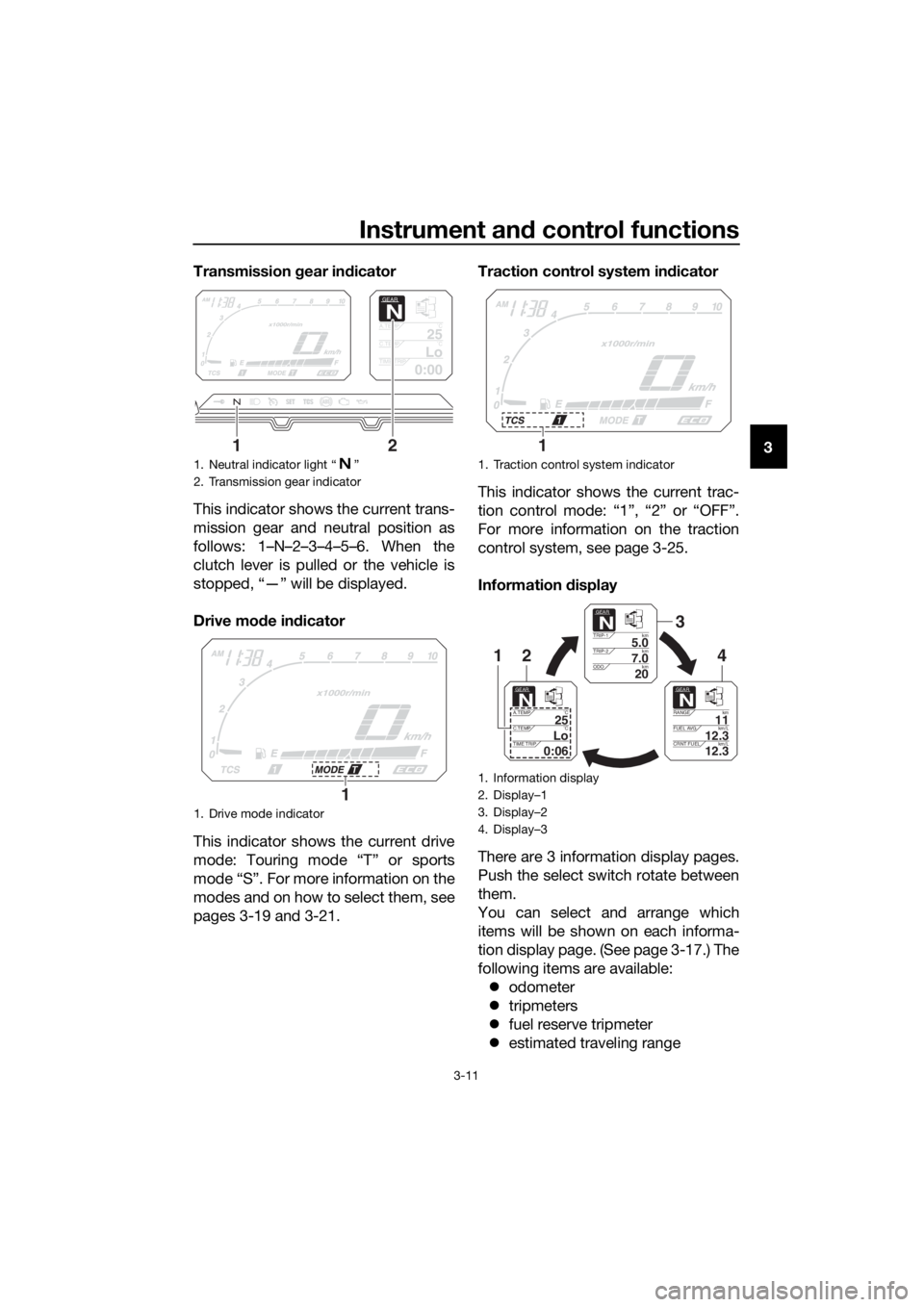
Transmission
gear in dicator
This indicator shows the current trans-
mission gear and neutral position as
follows: 1–N–2–3–4–5–6. When the
clutch lever is pulled or the vehicle is
stopped, “—” will be displayed.
Drive mo de in dicator
This indicator shows the current drive
mode: Touring mode “T” or sports
mode “S”. For more information on the
modes and on how to select them, see
pages 3-19 and 3-21. Traction control system in
dicator
This indicator shows the current trac-
tion control mode: “1”, “2” or “OFF”.
For more information on the traction
control system, see page 3-25.
Information display
There are 3 information display pages.
Push the select switch rotate between
them.
You can select and arrange which
items will be shown on each informa-
tion display page. (See page 3-17.) The
following items are available: odometer
tripmeters
fuel reserve tripmeter
estimated traveling range
1. Neutral indicator light “ ”
2. Transmission gear indicator
1. Drive mode indicator
GEAR
N
25A.TEMP ˚C
LoC.TEMP ˚C
0:00TIME TRIP
12
1
1. Traction control system indicator
1. Information display
2. Display–1
3. Display–2
4. Display–3
1
GEARN
5.0TRIP-1km
7.0TRIP-2km
km
20ODO
GEARN
11RANGE km
12.3FUEL AVG km/L
km/L
12.3CRNT FUEL
GEARN
25A.TEMP ˚C
LoC.TEMP ˚C
0:06TIME TRIP
3
421
UBP8E1E0.book Page 11 Friday, September 14, 2018 11:35 AM
Page 39 of 118
Instrument and control functions
3-25
3
This ABS has a test mode which
allows the owner to experience
the pulsation at the brake lever or
brake pedal when the ABS is op-
erating. However, special tools are
required, so please consult your
Yamaha dealer.
NOTICE
ECA16831
Keep any type of mag nets (includin g
ma gnetic pick-up tools, mag netic
screwd rivers, etc.) away from the
front an d rear wheel hu bs; other-
wise, the ma gnetic rotors equippe d
in the wheel hu bs may b e damag ed ,
resultin g in improper performance
of the ABS an d the unified b rake
system.
EAU58954
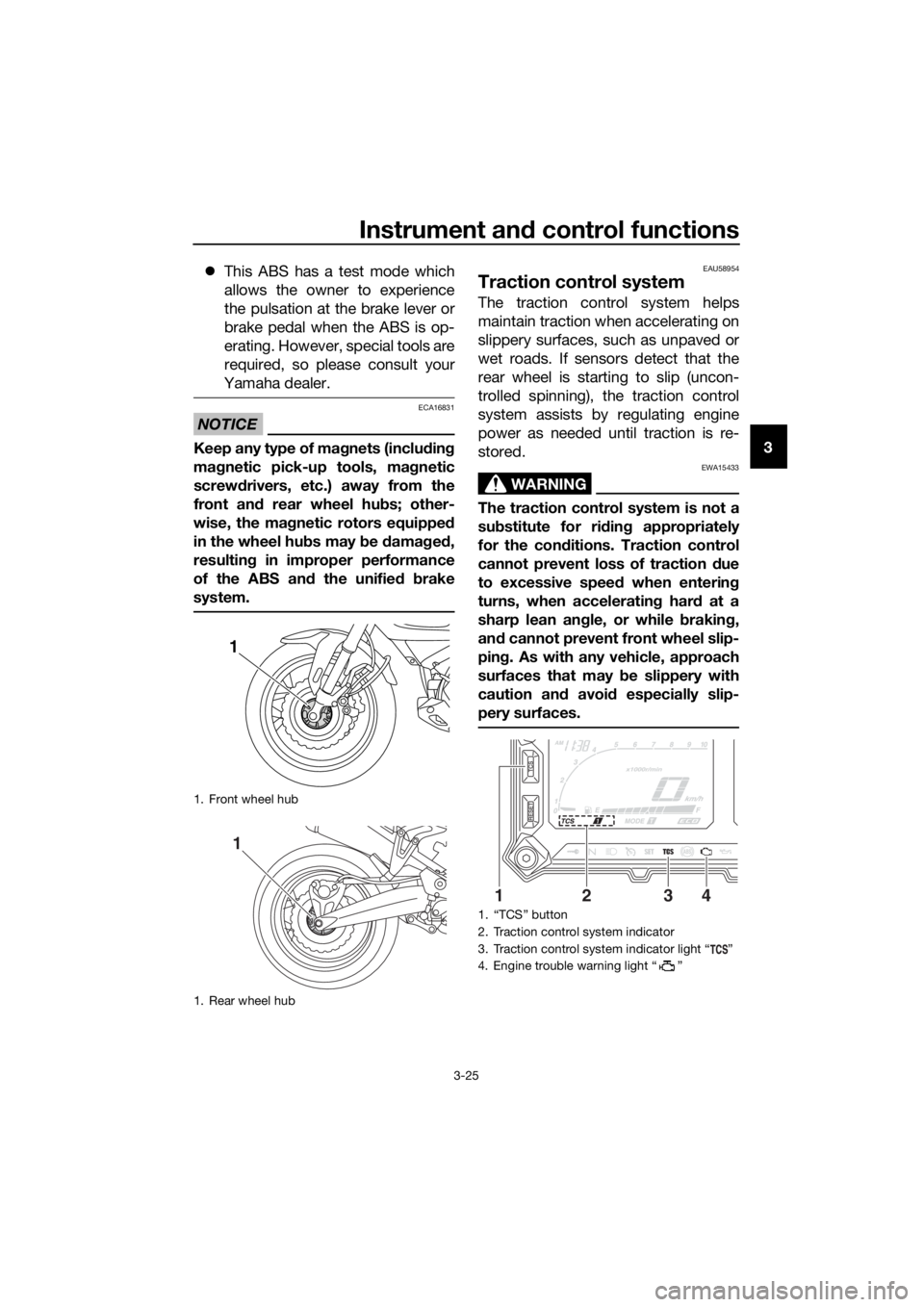
Traction control system
The traction control system helps
maintain traction when accelerating on
slippery surfaces, such as unpaved or
wet roads. If sensors detect that the
rear wheel is starting to slip (uncon-
trolled spinning), the traction control
system assists by regulating engine
power as needed until traction is re-
stored.
WARNING
EWA15433
The traction control system is not a
su bstitute for ri din g appropriately
for the con ditions. Traction control
cannot prevent loss of traction d ue
to excessive spee d when enterin g
turns, when acceleratin g har d at a
sharp lean an gle, or while b raking,
an d cannot prevent front wheel slip-
pin g. As with any vehicle, approach
surfaces that may be slippery with
caution an d avoi d especially slip-
pery surfaces.
1. Front wheel hub
1. Rear wheel hub
1
1
1. “TCS” button
2. Traction control system indicator
3. Traction control system indicator light “ ”
4. Engine trouble warning light “ ”
1324
UBP8E1E0.book Page 25 Friday, September 14, 2018 11:35 AM
Page 40 of 118
Instrument and control functions
3-26
3 The traction control system indicator
light flashes when traction control has
engaged. You may notice slight chang-
es in engine and exhaust sounds when
the system has engaged.
When the vehicle is turned on, the trac-
tion control system is turned on and
set to “TCS 1”. The traction control
system modes are as follows.
“TCS 1”
: Default mode
“TCS 2” : Sporty mode
This mode decreases traction control
system assist, allowing the rear wheel
to spin more freely than “TCS 1”.
“TCS OFF” : The traction control sys-
tem is turned off. The system may also
be automatically disabled in some rid-
ing conditions.
TIP
Use the mode “TCS OFF” to help free
the rear wheel if the motorcycle gets
stuck in mud, sand, or other soft sur-
faces.
NOTICE
ECA16801
Use only the specifie d tires. (See
pa ge 6-19.) Usin g different sized
tires will prevent the traction control
system from controllin g tire rotation
accurately.
Settin g the traction control system
WARNING
EWA15441
Be sure to stop the vehicle before
makin g any settin g chan ges to the
traction control system. Chan gin g
settin gs while ri din g can d istract the
operator an d increase the risk of an
acci dent.
The traction control system mode can
be changed only when the vehicle is
stopped.
Push the “TCS” button to change
between modes “1” and “2”.
Push the button for two seconds
to select “TCS OFF” and turn the
traction control system off. Push
the button again to return to the
previously selected mode.
Resetting
The traction control system will disable
in the following conditions: excessive rear wheel spinning
the front or rear wheel comes off
the ground while riding
either wheel is rotated with the key
turned to “ON” (such as when per-
forming maintenance)
If the traction control system has been
disabled, both the traction control sys-
tem indicator light and the engine trou-
ble warning light come on.
Should this occur, try resetting the sys-
tem as follows. 1. Stop the vehicle and turn the key to “OFF”.
2. Wait a few seconds and then turn the key back to “ON”.
3. The traction control system indi- cator light should turn off and the
system be enabled.
TIP
If the traction control system indicator
light remains on after resetting, the mo-
torcycle may still be ridden. However,
have a Yamaha dealer check the vehi-
cle as soon as possible.
UBP8E1E0.book Page 26 Friday, September 14, 2018 11:35 AM
Page 61 of 118

Operation and important ri din g points
5-4
5
The neutral indicator light should
come on and then the clutch lever
can be released.
WARNING
EWA17380
Improper brakin g can cause
loss of control or traction. Al-
ways use both brakes an d apply
them smoothly.
Make sure that the motorcycle
and the eng ine have sufficiently
slowe d b efore shiftin g to a low-
er gear. En gag in g a lower gear
when the vehicle or en gine
speed is too hi gh coul d make
the rear wheel lose traction or
the en gine to over-rev. This
coul d cause loss of control, an
acci dent an d injury. It coul d also
cause en gine or d rive train dam-
a g e.
EAU16811
Tips for re ducin g fuel con-
sumption
Fuel consumption depends largely on
your riding style. Consider the follow-
ing tips to reduce fuel consumption:
Shift up swiftly, and avoid high en-
gine speeds during acceleration.
Do not rev the engine while shift-
ing down, and avoid high engine
speeds with no load on the en-
gine.
Turn the engine off instead of let-
ting it idle for an extended length
of time (e.g., in traffic jams, at traf-
fic lights or at railroad crossings).
UBP8E1E0.book Page 4 Friday, September 14, 2018 11:35 AM
Page 116 of 118

Index
10-2
10
T
Throttle grip and cable, checking and
lubricating ........................................... 6-26
Throttle grip free play, checking ........... 6-18
Tires ...................................................... 6-19
Tool kit .................................................... 6-2
Traction control system ........................ 3-25
Traction control system indicator light ... 3-5
Troubleshooting .................................... 6-39
Troubleshooting charts ......................... 6-40
Turn signal indicator lights ...................... 3-3
Turn signal light and brake/tail light ...... 6-37
Turn signal switch ................................. 3-20
V
Valve clearance..................................... 6-19
Vehicle identification number ................. 9-1
W
Wheel bearings, checking..................... 6-30
Wheels .................................................. 6-22
Windshield ............................................ 3-33
Y
Yamalube .............................................. 6-13
UBP8E1E0.book Page 2 Friday, September 14, 2018 11:35 AM