ABS YAMAHA XT1200ZE 2015 Owners Manual
[x] Cancel search | Manufacturer: YAMAHA, Model Year: 2015, Model line: XT1200ZE, Model: YAMAHA XT1200ZE 2015Pages: 118, PDF Size: 3.13 MB
Page 6 of 118

TABLE OF CONTENTSSAFETY INFORMATION.................. 1-1
DESCRIPTION .................................. 2-1
Left view ......................................... 2-1
Right view ....................................... 2-2
Controls and instruments ............... 2-3
INSTRUMENT AND CONTROL
FUNCTIONS ...................................... 3-1
Immobilizer system......................... 3-1
Main switch/steering lock............... 3-2
Indicator lights and warning lights............................................ 3-4
Cruise control system..................... 3-7
Multi-function meter unit .............. 3-10
D-mode (drive mode).................... 3-24
Handlebar switches ...................... 3-24
Clutch lever .................................. 3-26
Shift pedal .................................... 3-27
Brake lever.................................... 3-27
Brake pedal .................................. 3-28
ABS .............................................. 3-28
Traction control system ................ 3-29
Fuel tank cap ................................ 3-31
Fuel ............................................... 3-32
Fuel tank breather hose and
overflow hose ............................ 3-33
Catalytic converter ....................... 3-33
Rider seat ..................................... 3-34
Adjusting the rider seat height...... 3-35
Windshield .................................... 3-36 Adjusting the front and rear
suspension ................................ 3-37
Carriers.......................................... 3-42
Luggage strap holders .................. 3-42
Sidestand ...................................... 3-43
Ignition circuit cut-off system ....... 3-43
Auxiliary DC jack ........................... 3-45
FOR YOUR SAFETY –
PRE-OPERATION CHECKS ............. 4-1
OPERATION AND IMPORTANT
RIDING POINTS ................................ 5-1
Starting the engine .......................... 5-1
Shifting ............................................ 5-2
Tips for reducing fuel consumption ................................ 5-3
Engine break-in ............................... 5-3
Parking ............................................ 5-4
PERIODIC MAINTENANCE AND
ADJUSTMENT ................................... 6-1
Owner’s tool kit ............................... 6-2
Periodic maintenance chart for the
emission control system .............. 6-3
General maintenance and
lubrication chart ........................... 6-4
Removing and installing cowlings... 6-8
Checking the spark plugs ............. 6-10
Engine oil and oil filter cartridge.... 6-11
Final gear oil .................................. 6-14 Coolant ......................................... 6-15
Air filter element ............................ 6-17
Checking the engine idling
speed ........................................ 6-17
Checking the throttle grip free
play ............................................ 6-17
Valve clearance............................. 6-18
Tires .............................................. 6-18
Spoke wheels ............................... 6-20
Clutch lever................................... 6-21
Checking the brake lever free play ............................................ 6-21
Brake light switches ..................... 6-22
Checking the front and rear brake pads .......................................... 6-22
Checking the brake fluid level ...... 6-23
Changing the brake and clutch fluids .......................................... 6-24
Checking and lubricating the throttle grip and cable ............... 6-24
Checking and lubricating the brake and shift pedals............... 6-25
Checking and lubricating the
brake and clutch levers ............. 6-25
Checking and lubricating the centerstand and sidestand........ 6-26
Lubricating the swingarm pivots......................................... 6-27
Checking the front fork ................. 6-27
Checking the steering................... 6-28
Checking the wheel bearings ....... 6-28U2KBE1E0.book Page 1 Monday, August 18, 2014 9:42 AM
Page 19 of 118
INSTRUMENT AND CONTROL FUNCTIONS
3-4
3
EAU49397
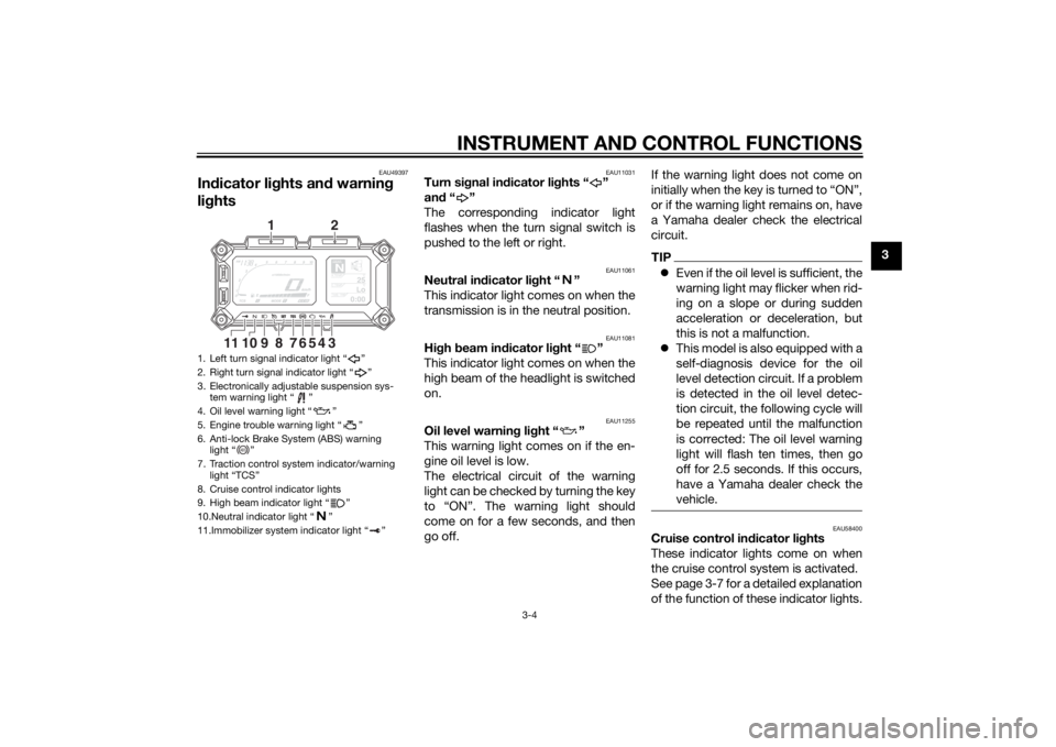
Indicator lig hts and warning
lig hts
EAU11031
Turn si gnal in dicator li ghts “ ”
an d“”
The corresponding indicator light
flashes when the turn signal switch is
pushed to the left or right.
EAU11061
Neutral in dicator li ght “ ”
This indicator light comes on when the
transmission is in the neutral position.
EAU11081
Hi gh beam in dicator li ght “ ”
This indicator light comes on when the
high beam of the headlight is switched
on.
EAU11255
Oil level warnin g lig ht “ ”
This warning light comes on if the en-
gine oil level is low.
The electrical circuit of the warning
light can be checked by turning the key
to “ON”. The warning light should
come on for a few seconds, and then
go off. If the warning light does not come on
initially when the key is turned to “ON”,
or if the warning light remains on, have
a Yamaha dealer check the electrical
circuit.
TIP
Even if the oil level is sufficient, the
warning light may flicker when rid-
ing on a slope or during sudden
acceleration or deceleration, but
this is not a malfunction.
This model is also equipped with a
self-diagnosis device for the oil
level detection circuit. If a problem
is detected in the oil level detec-
tion circuit, the following cycle will
be repeated until the malfunction
is corrected: The oil level warning
light will flash ten times, then go
off for 2.5 seconds. If this occurs,
have a Yamaha dealer check the
vehicle.
EAU58400
Cruise control in dicator li ghts
These indicator lights come on when
the cruise control system is activated.
See page 3-7 for a detailed explanation
of the function of these indicator lights.
1. Left turn signal indicator light “ ”
2. Right turn signal indicator light “ ”
3. Electronically adjustable suspension sys- tem warning light “ ”
4. Oil level warning light “ ”
5. Engine trouble warning light “ ”
6. Anti-lock Brake System (ABS) warning light “ ”
7. Traction control system indicator/warning light “TCS”
8. Cruise control indicator lights
9. High beam indicator light “ ”
10.Neutral indicator light “ ”
11.Immobilizer system indicator light “ ”
GEARN
25
A.TEMP ˚C
Lo
C.TEMP˚C
0:00
TIME TRIP34567
9
8
1011
1
2
ABS
U2KBE1E0.book Page 4 Monday, August 18, 2014 9:42 AM
Page 20 of 118
INSTRUMENT AND CONTROL FUNCTIONS
3-5
3The electrical circuit of these indicator
lights can be checked by turning the
key to “ON”. These indicator lights
should come on for a few seconds,
and then go off.
If an indicator light does not come on
initially when the key is turned to “ON”,
or if an indicator light remains on, have
a Yamaha dealer check the electrical
circuit.
EAU59110
En
gine trou ble warnin g lig ht “ ”
This warning light comes on or flashes
if a problem is detected in the electrical
circuit monitoring the engine. If this oc-
curs, have a Yamaha dealer check the
self-diagnosis system. (See page 3-23
for an explanation of the self-diagnosis
device.)
The electrical circuit of the warning
light can be checked by turning the key
to “ON”. The warning light should
come on for a few seconds, and then
go off. If the warning light does not come on
initially when the key is turned to “ON”,
or if the warning light remains on, have
a Yamaha dealer check the electrical
circuit.
TIPThe engine trouble warning light will
come on while the start switch is
pushed, but this does not indicate a
malfunction.
EAU59120
ABS warnin
g li ght “ ”
In normal operation, the ABS warning
light comes on when the key is turned
to “ON”, and goes off after traveling at
a speed of 10 km/h (6 mi/h) or higher.
If the ABS warning light: does not come on when the key is
turned to “ON”
comes on or flashes while riding
does not go off after traveling at a
speed of 10 km/h (6 mi/h) or high-
er
The ABS may not work correctly. If any
of the above occurs, have a Yamaha
dealer check the system as soon as
possible. (See page 3-28 for an expla-
nation of the ABS.)
WARNING
EWA16041
If the ABS warnin g li ght does not g o
off after travelin g at a speed of 10
km/h (6 mi/h) or hi gher, or if the
warnin g li ght comes on or flashes
while ri din g, the brake system re-
verts to conventional brakin g. If ei-
ther of the a bove occurs, or if the
warnin g li ght does not come on at
all, use extra caution to avoi d possi-
b le wheel lock durin g emer gency
b rakin g. Have a Yamaha d ealer
check the brake system an d electri-
cal circuits as soon as possi ble.TIPThe ABS warning light will also come
on while the start switch is pushed, but
this does not indicate a malfunction.
EAU58902
Traction control system in dica-
tor/warnin g lig ht “TCS”
This indicator/warning light flashes
when the traction control system en-
gages.
ABS
U2KBE1E0.book Page 5 Monday, August 18, 2014 9:42 AM
Page 40 of 118
INSTRUMENT AND CONTROL FUNCTIONS
3-25
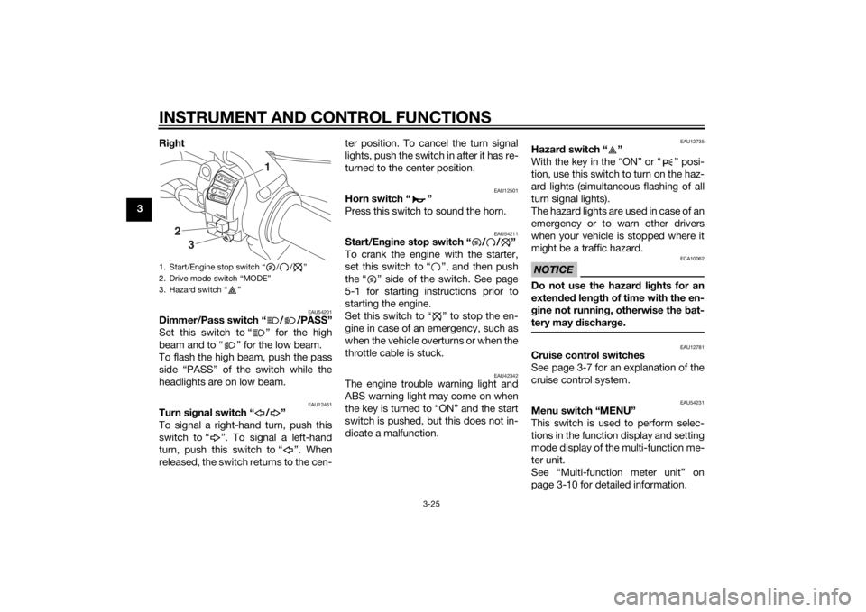
3Ri
ght
EAU54201
Dimmer/Pass switch “ / /PASS”
Set this switch to “ ” for the high
beam and to “ ” for the low beam.
To flash the high beam, push the pass
side “PASS” of the switch while the
headlights are on low beam.
EAU12461
Turn si gnal switch “ / ”
To signal a right-hand turn, push this
switch to “ ”. To signal a left-hand
turn, push this switch to “ ”. When
released, the switch returns to the cen- ter position. To cancel the turn signal
lights, push the switch in after it has re-
turned to the center position.
EAU12501
Horn switch “ ”
Press this switch to sound the horn.
EAU54211
Start/En
gine stop switch “ / / ”
To crank the engine with the starter,
set this switch to “ ”, and then push
the “ ” side of the switch. See page
5-1 for starting instructions prior to
starting the engine.
Set this switch to “ ” to stop the en-
gine in case of an emergency, such as
when the vehicle overturns or when the
throttle cable is stuck.
EAU42342
The engine trouble warning light and
ABS warning light may come on when
the key is turned to “ON” and the start
switch is pushed, but this does not in-
dicate a malfunction.
EAU12735
Hazar d switch “ ”
With the key in the “ON” or “ ” posi-
tion, use this switch to turn on the haz-
ard lights (simultaneous flashing of all
turn signal lights).
The hazard lights are used in case of an
emergency or to warn other drivers
when your vehicle is stopped where it
might be a traffic hazard.NOTICE
ECA10062
Do not use the hazard lights for an
exten ded len gth of time with the en-
g ine not runnin g, otherwise the bat-
tery may dischar ge.
EAU12781
Cruise control switches
See page 3-7 for an explanation of the
cruise control system.
EAU54231
Menu switch “MENU”
This switch is used to perform selec-
tions in the function display and setting
mode display of the multi-function me-
ter unit.
See “Multi-function meter unit” on
page 3-10 for detailed information.
1. Start/Engine stop switch “ / / ”
2. Drive mode switch “MODE”
3. Hazard switch “ ”
MODESTOPRUNS TA R
T
3
2
1
U2KBE1E0.book Page 25 Monday, August 18, 2014 9:42 AM
Page 43 of 118
INSTRUMENT AND CONTROL FUNCTIONS
3-28
3
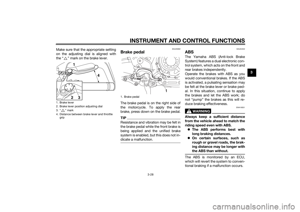
Make sure that the appropriate setting
on the adjusting dial is aligned with
the “ ” mark on the brake lever.
EAU49482
Brake ped
alThe brake pedal is on the right side of
the motorcycle. To apply the rear
brake, press down on the brake pedal.TIPResistance and vibration may be felt in
the brake pedal while the front brake is
being applied and the unified brake
system is enabled, but this does not in-
dicate a malfunction.
EAU54532
ABSThe Yamaha ABS (Anti-lock Brake
System) features a dual electronic con-
trol system, which acts on the front and
rear brakes independently.
Operate the brakes with ABS as you
would conventional brakes. If the ABS
is activated, a pulsating sensation may
be felt at the brake lever or brake ped-
al. In this situation, continue to apply
the brakes and let the ABS work; do
not “pump” the brakes as this will re-
duce braking effectiveness.
WARNING
EWA16051
Always keep a sufficient d istance
from the vehicle ahea d to match the
ri din g speed even with ABS.
The ABS performs b est with
lon g b rakin g d istances.
On certain surfaces, such as
rou gh or g ravel roa ds, the b rak-
in g d istance may be lon ger with
the ABS than without.The ABS is monitored by an ECU,
which will revert the system to conven-
tional braking if a malfunction occurs.
1. Brake lever
2. Brake lever position adjusting dial
3. “ ” mark
4. Distance between brake lever and throttle grip
5
43
211
4
3
2
1. Brake pedal
1
U2KBE1E0.book Page 28 Monday, August 18, 2014 9:42 AM
Page 44 of 118
INSTRUMENT AND CONTROL FUNCTIONS
3-29
3
TIPThe ABS performs a self-diagno-
sis test each time the vehicle first
starts off after the key is turned to
“ON” and the vehicle has traveled
at a speed of 10 km/h (6 mi/h) or
higher. During this test, a “click-
ing” noise can be heard from un-
der the seat, and if the brake lever
or brake pedal is even slightly ap-
plied, a vibration can be felt at the
lever and pedal, but these do not
indicate a malfunction.
This ABS has a test mode which
allows the owner to experience
the pulsation at the brake lever or
brake pedal when the ABS is op-
erating. However, special tools are
required, so please consult your
Yamaha dealer.NOTICE
ECA16831
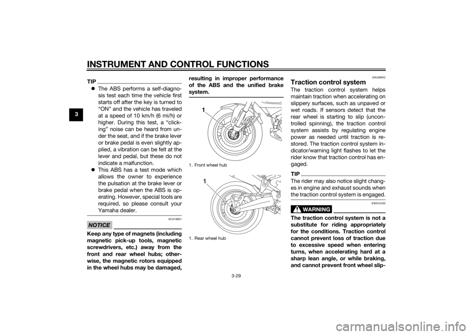
Keep any type of mag nets (includin g
ma gnetic pick-up tools, ma gnetic
screwd rivers, etc.) away from the
front an d rear wheel hu bs; other-
wise, the ma gnetic rotors equippe d
in the wheel hu bs may be damag ed , resultin
g in improper performance
of the ABS an d the unifie d b rake
system.
EAU58942
Traction control systemThe traction control system helps
maintain traction when accelerating on
slippery surfaces, such as unpaved or
wet roads. If sensors detect that the
rear wheel is starting to slip (uncon-
trolled spinning), the traction control
system assists by regulating engine
power as needed until traction is re-
stored. The traction control system in-
dicator/warning light flashes to let the
rider know that traction control has en-
gaged.TIPThe rider may also notice slight chang-
es in engine and exhaust sounds when
the traction control system is engaged.
WARNING
EWA15432
The traction control system is not a
su bstitute for rid ing appropriately
for the con ditions. Traction control
cannot prevent loss of traction due
to excessive speed when entering
turns, when acceleratin g har d at a
sharp lean an gle, or while brakin g,
an d cannot prevent front wheel slip-
1. Front wheel hub
1. Rear wheel hub
11
U2KBE1E0.book Page 29 Monday, August 18, 2014 9:42 AM
Page 52 of 118
INSTRUMENT AND CONTROL FUNCTIONS
3-37
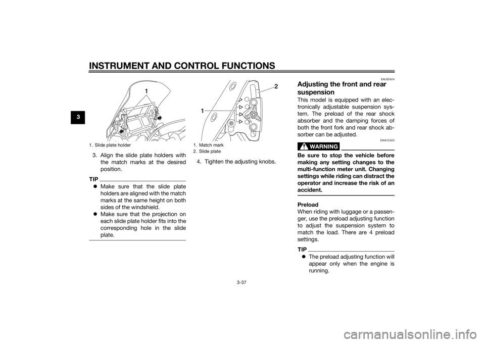
33. Align the slide plate holders withthe match marks at the desired
position.
TIPMake sure that the slide plate
holders are aligned with the match
marks at the same height on both
sides of the windshield.
Make sure that the projection on
each slide plate holder fits into the
corresponding hole in the slide
plate.
4. Tighten the adjusting knobs.
EAU55424
Adjustin g the front an d rear
suspensionThis model is equipped with an elec-
tronically adjustable suspension sys-
tem. The preload of the rear shock
absorber and the damping forces of
both the front fork and rear shock ab-
sorber can be adjusted.
WARNING
EWA12423
Be sure to stop the vehicle before
makin g any settin g chan ges to the
multi-function meter unit. Chan gin g
settin gs while ri din g can distract the
operator an d increase the risk of an
acci dent.Preloa d
When riding with luggage or a passen-
ger, use the preload adjusting function
to adjust the suspension system to
match the load. There are 4 preload
settings.TIP The preload adjusting function will
appear only when the engine is
running.
1. Slide plate holder
1
1. Match mark
2. Slide plate
2
1
U2KBE1E0.book Page 37 Monday, August 18, 2014 9:42 AM
Page 64 of 118
OPERATION AND IMPORTANT RIDING POINTS
5-2
5
NOTICE
ECA11834
If a warning or in dicator li ght does
not come on initially when the key is
turne d to “ON”, or if a warning or in-
d icator li ght remains on, see pag e
3-4 for the correspon din g warnin g
an d in dicator li ght circuit check.
The ABS warning light should
come on when the key is turned to
“ON”, and then go off after travel-
ing at a speed of 10 km/h (6 mi/h)
or higher.
NOTICE
ECA17682
If the ABS warnin g lig ht does not
come on an d then g o off as ex-
plaine d a bove, see pa ge 3-4 for the
warnin g lig ht circuit check.2. Shift the transmission into the
neutral position. The neutral indi-
cator light should come on. If not,
ask a Yamaha dealer to check the
electrical circuit.
3. Start the engine by pushing the “ ” side of the start/engine
stop switch. If the engine fails to start, release
the start/engine stop switch, wait
a few seconds, and then try again.
Each starting attempt should be
as short as possible to preserve
the battery. Do not crank the en-
gine more than 10 seconds on any
one attempt.
NOTICE
ECA11043
For maximum en
gine life, never ac-
celerate har d when the en gine is
col d!
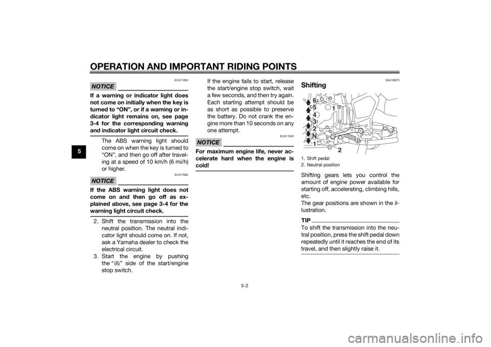
EAU16673
Shiftin gShifting gears lets you control the
amount of engine power available for
starting off, accelerating, climbing hills,
etc.
The gear positions are shown in the il-
lustration.TIPTo shift the transmission into the neu-
tral position, press the shift pedal down
repeatedly until it reaches the end of its
travel, and then slightly raise it.1. Shift pedal
2. Neutral position
1
2
654321N
U2KBE1E0.book Page 2 Monday, August 18, 2014 9:42 AM
Page 89 of 118
PERIODIC MAINTENANCE AND ADJUSTMENT
6-23
6
EAU40262
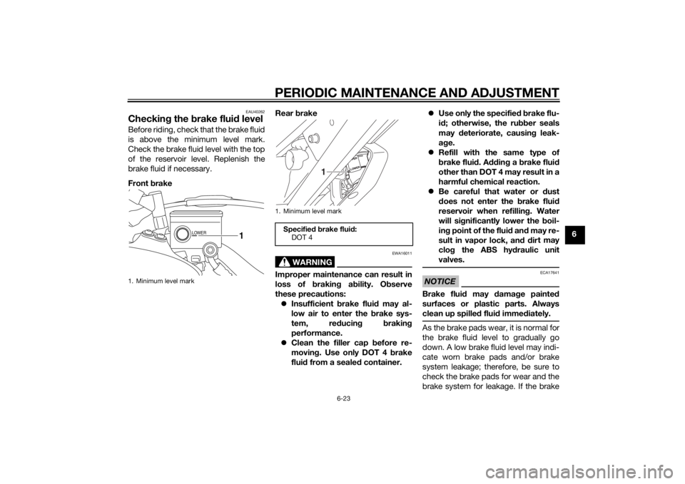
Checking the brake flui d levelBefore riding, check that the brake fluid
is above the minimum level mark.
Check the brake fluid level with the top
of the reservoir level. Replenish the
brake fluid if necessary.
Front brake Rear
brake
WARNING
EWA16011
Improper maintenance can result in
loss of b raking a bility. O bserve
these precautions: Insufficient brake flui d may al-
low air to enter the b rake sys-
tem, re ducin g brakin g
performance.
Clean the filler cap before re-
movin g. Use only DOT 4 b rake
flui d from a seale d container.
Use only the specifie d b rake flu-
i d ; otherwise, the ru bber seals
may deteriorate, causin g leak-
a g e.
Refill with the same type of
brake flui d. A dding a brake flui d
other than DOT 4 may result in a
harmful chemical reaction.
Be careful that water or dust
d oes not enter the brake flui d
reservoir when refilling . Water
will si gnificantly lower the boil-
in g point of the flui d an d may re-
sult in vapor lock, an d d ir
t may
clo g the ABS hy draulic unit
valves.
NOTICE
ECA17641
Brake flui d may damag e painte d
surfaces or plastic parts. Always
clean up spille d flui d imme diately.As the brake pads wear, it is normal for
the brake fluid level to gradually go
down. A low brake fluid level may indi-
cate worn brake pads and/or brake
system leakage; therefore, be sure to
check the brake pads for wear and the
brake system for leakage. If the brake
1. Minimum level mark
LOWER
1
1. Minimum level mark
Specified b rake flui d:
DOT 4
1
U2KBE1E0.book Page 23 Monday, August 18, 2014 9:42 AM
Page 96 of 118
PERIODIC MAINTENANCE AND ADJUSTMENT
6-30
6
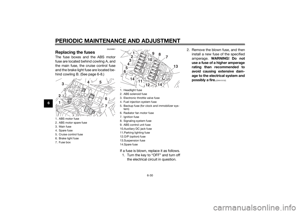
EAU58961
Replacing the fusesThe fuse boxes and the ABS motor
fuse are located behind cowling A, and
the main fuse, the cruise control fuse
and the brake light fuse are located be-
hind cowling B. (See page 6-8.)
If a fuse is blown, replace it as follows.1. Turn the key to “OFF” and turn off the electrical circuit in question. 2. Remove the blown fuse, and then
install a new fuse of the specified
amperage. WARNING! Do not
use a fuse of a hi gher ampera ge
ratin g than recommen ded to
avoi d causin g extensive d am-
a g e to the electrical system an d
possi bly a fire.
[EWA15132]
1. ABS motor fuse
2. ABS motor spare fuse
3. Main fuse
4. Spare fuse
5. Cruise control fuse
6. Brake light fuse
7. Fuse box123
5
67
4
1. Headlight fuse
2. ABS solenoid fuse
3. Electronic throttle valve fuse
4. Fuel injection system fuse
5. Backup fuse (for clock and immobilizer sys-
tem)
6. Radiator fan motor fuse
7. Ignition fuse
8. Signaling system fuse
9. ABS control unit fuse
10.Auxiliary DC jack fuse
11.Parking lighting fuse
12.O/P (option) fuse
13.Suspension fuse
14.Spare fuse
13456
2
7
8
9
10
14
13
11
12
14
U2KBE1E0.book Page 30 Monday, August 18, 2014 9:42 AM