check engine YAMAHA XT1200ZE 2019 User Guide
[x] Cancel search | Manufacturer: YAMAHA, Model Year: 2019, Model line: XT1200ZE, Model: YAMAHA XT1200ZE 2019Pages: 122, PDF Size: 3.88 MB
Page 56 of 122
Instrument and control functions
3-42
3 5. Turn the main switch on, and start
the engine. (See page 5-2.)
6. Turn the accessory on.
WARNING
EWA14361
To prevent electrical shock or short-
circuitin g, make sure that the cap is
installe d when the auxiliary DC jack
is not b eing use d.
EAU15306
Si destan d
The sidestand is located on the left
side of the frame. Raise the sidestand
or lower it with your foot while holding
the vehicle upright.
TIP
The built-in sidestand switch is part of
the ignition circuit cut-off system,
which cuts the ignition in certain situa-
tions. (See the following section for an
explanation of the ignition circuit cut-
off system.)
WARNING
EWA10242
The vehicle must not be ri dden with
the si destan d d own, or if the si de-
stan d cannot b e properly move d up
(or does not stay up), otherwise the
si destan d coul d contact the groun d
an d d istract the operator, resultin g
in a possi ble loss of control.
Yamaha’s ig nition circuit cut-off
system has been desi gne d to assist
the operator in fulfillin g the respon-
si bility of raisin g the si destan d b e-
fore startin g off. Therefore, check
this system re gularly an d have a
Yamaha dealer repair it if it does not
function properly.
UBP9E1E0.book Page 42 Friday, September 7, 2018 10:01 AM
Page 57 of 122

Instrument and control functions
3-43
3
EAU63431
Ig nition circuit cut-off system
This system prevents in-gear engine
starts unless the clutch lever is pulled
and the sidestand is up. Also, it will
stop the running engine should the
sidestand be lowered while the trans-
mission is in gear.
Periodically check the system via the
following procedure.
TIP
This check is most reliable if per-
formed with a warmed-up engine.
See pages 3-2 and 3-22 for switch
operation information.
UBP9E1E0.book Page 43 Friday, September 7, 2018 10:01 AM
Page 58 of 122
Instrument and control functions
3-44
3
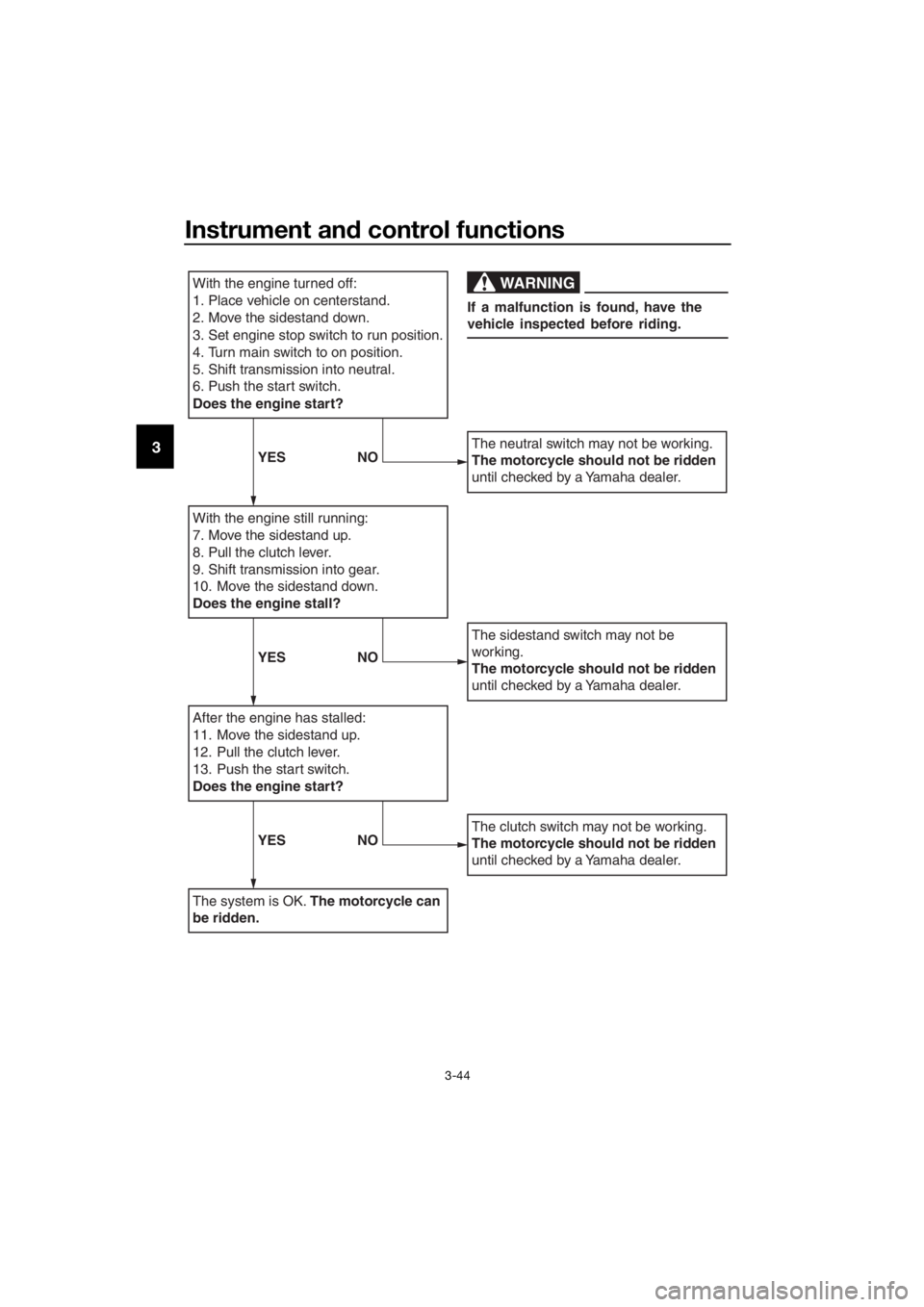
With the engine turned off:
1. Place vehicle on centerstand.
2. Move the sidestand down.
3. Set engine stop switch to run position.
4. Turn main switch to on position.
5. Shift transmission into neutral.
6. Push the start switch.
Does the engine start?
With the engine still running:
7. Move the sidestand up.
8. Pull the clutch lever.
9. Shift transmission into gear.
10. Move the sidestand down.
Does the engine stall?
After the engine has stalled:
11. Move the sidestand up.
12. Pull the clutch lever.
13. Push the start switch.
Does the engine start?
The system is OK. The motorcycle can
be ridden.
The neutral switch may not be working.
The motorcycle should not be ridden
until checked by a Yamaha dealer.
The sidestand switch may not be
working.
The motorcycle should not be ridden
until checked by a Yamaha dealer.
The clutch switch may not be working.
The motorcycle should not be ridden
until checked by a Yamaha dealer.
WARNING
If a malfunction is found, have the
vehicle inspected before riding.
YES NO
YESNO
YESNO
UBP9E1E0.book Page 44 Friday, September 7, 2018 10:01 AM
Page 59 of 122

For your safety – pre-operation checks
4-1
4
EAU63441
Inspect your vehicle each time you use it to make sure the vehicle is in safe oper-
ating condition. Always follow the inspection and maintenance procedures and
schedules described in the Owner’s Manual.
WARNING
EWA11152
Failure to inspect or maintain the vehicle properly increases the possibility
of an acci dent or equipment d amage. Do not operate the vehicle if you fin d
any prob lem. If a pro blem cannot be corrected b y the proce dures provi ded
in this manual, have the vehicle inspecte d b y a Yamaha d ealer.
Before using this vehicle, check the following points:
ITEM CHECKSPAGE
Fuel • Check fuel level in fuel tank.
• Refuel if necessary.
• Check fuel line for leakage.
• Check fuel tank breather hose and overflow hose for
obstructions, cracks or damage, and check hose con-
nections. 3-29,
3-31
En gine oil • Check oil level in engine.
• If necessary, add recommended oil to specified level.
• Check vehicle for oil leakage. 6-10
Final gear oil • Check vehicle for oil leakage. 6-14
Coolant • Check coolant level in reservoir.
• If necessary, add recommended coolant to specified
level.
• Check cooling system for leakage. 6-16
Front brake • Check operation.
• If soft or spongy, have Yamaha dealer bleed hydraulic
system.
• Check brake pads for wear.
• Replace if necessary.
• Check fluid level in reservoir.
• If necessary, add specified brake fluid to specified level.
• Check hydraulic system for leakage. 6-24,
6-25
Rear brake • Check operation.
• If soft or spongy, have Yamaha dealer bleed hydraulic
system.
• Check brake pads for wear.
• Replace if necessary.
• Check fluid level in reservoir.
• If necessary, add specified brake fluid to specified level.
• Check hydraulic system for leakage. 6-24,
6-25
Clutch • Check operation.
• If soft or spongy, have Yamaha dealer bleed hydraulic
system.
• Check hydraulic system for leakage. 6-22
UBP9E1E0.book Page 1 Friday, September 7, 2018 10:01 AM
Page 62 of 122
Operation and important rid ing points
5-2
5
EAU58242
Startin g the en gine
In order for the ignition circuit cut-off
system to enable starting, one of the
following conditions must be met:
The transmission is in the neutral
position.
The transmission is in gear with
the clutch lever pulled and the
sidestand up.
See page 3-43 for more informa-
tion.
1. Turn the key to “ON” and make sure that the start/engine stop
switch is set to “ ”.
The following warning lights and
indicator lights should come on for
a few seconds, then go off. Oil level warning light
Engine trouble warning light
Traction control system indi-
cator light
Cruise control indicator lights
Suspension sy stem warning
light
Immobilizer system indicator
light
NOTICE
ECA11834
If a warnin g or in dicator li ght does
not come on initially when the key is
turne d to “ON”, or if a warnin g or in-
d icator li ght remains on, see pag e
3-3 for the correspon din g warnin g
an d in dicator li ght circuit check.
The ABS warning light should
come on when the key is turned to
“ON”, and then go off after travel-
ing at a speed of 10 km/h (6 mi/h)
or higher.
NOTICE
ECA17682
If the ABS warnin g li ght does not
come on an d then g o off as ex-
plained above, see pag e 3-3 for the
warnin g lig ht circuit check.
2. Shift the transmission into the
neutral position. The neutral indi-
cator light should come on. If not,
ask a Yamaha dealer to check the
electrical circuit.
3. Start the engine by pushing the “ ” side of the start/engine
stop switch.
If the engine fails to start, release
the start/engine stop switch, wait
a few seconds, and then try again.
Each starting attempt should be
as short as possible to preserve
the battery. Do not crank the en-
gine more than 10 seconds on any
one attempt.
NOTICE
ECA11043
For maximum en gine life, never ac-
celerate har d when the en gine is
col d!
UBP9E1E0.book Page 2 Friday, September 7, 2018 10:01 AM
Page 65 of 122

Operation and important ri din g points
5-5
5
EAU16842
En gine break-in
There is never a more important period
in the life of your engine than the period
between 0 and 1600 km (1000 mi). For
this reason, you should read the fol-
lowing material carefully.
Since the engine is brand new, do not
put an excessive load on it for the first
1600 km (1000 mi). The various parts in
the engine wear and polish themselves
to the correct operating clearances.
During this period, prolonged full-throt-
tle operation or any condition that
might result in engine overheating
must be avoided.
EAU58991
0–1000 km (0–600 mi)
Avoid prolonged operation above 3900
r/min. NOTICE: After 1000 km (600
mi) of operation, the en gine oil an d
final gear oil must be chan ged , an d
the oil filter cartri dge or element re-
place d.
[ECA10333]
1000–1600 km (600–1000 mi)
Avoid prolonged operation above 4700
r/min.
1600 km (1000 mi) an d b eyon d
The vehicle can now be operated nor-
mally.
NOTICE
ECA23060
Keep the en gine spee d out of
the tachometer hi gh-r/min zo-
ne.
If any en gine trou ble shoul d oc-
cur durin g the en gine break-in
period , imme diately have a
Yamaha dealer check the vehi-
cle.
UBP9E1E0.book Page 5 Friday, September 7, 2018 10:01 AM
Page 69 of 122

Periodic maintenance an d a djustment
6-3
6
EAU71033
Perio dic maintenance charts
TIP
Items marked with an asterisk should be performed by your Yamaha dealer
because these items require special tools, data, and technical skills.
From 50000 km (30000 mi), repeat the maintenance intervals starting from
10000 km (6000 mi).
The annual checks must be performe d every year, except if a distance-
b ased maintenance is performe d instea d.
EAU71071
Perio dic maintenance chart for the emission control system
NO. ITEM
1 *Fuel line • Check fuel hoses for cracks or
damage.
• Replace if necessary. √√√√√
2 *Spark plu gs • Check condition.
• Adjust gap and clean.
√√
• Replace. √√
3 *Valve clearance • Check and adjust. Every 40000 km (24000 mi)
4 *Fuel injection • Check engine idle speed.
√√√√√√
• Check and adjust synchroniza- tion. √√√√√
5 *Exhaust system • Check for leakage.
• Tighten if necessary.
• Replace gaskets if necessary. √√√√√
6 *Evaporative emis-
sion control sys-
tem • Check control system for dam-
age.
• Replace if necessary. √√X 1000 km
CHECK OR
MAINTENANCE JOB
X 1000 mi
ODOMETER READINGS
ANNUAL CHECK
110203040
0.66121824
UBP9E1E0.book Page 3 Friday, September 7, 2018 10:01 AM
Page 71 of 122

Periodic maintenance an d a djustment
6-5
6
13 *Chassis fasteners • Make sure that all nuts, bolts
and screws are properly tight-
ened. √√√√√
14 Brake lever pivot
shaft
• Lubricate with silicone grease.
√√√√√
15 Brake ped
al pivot
shaft • Lubricate with lithium-soap-
based grease. √√√√√
16 Clutch lever pivot
shaft • Lubricate with silicone grease.
√√√√√
17 Shift pe
dal pivot
shaft • Lubricate with lithium-soap-
based grease. √√√√√
18 Si
destan d, center-
stan d • Check operation.
• Lubricate with lithium-soap-
based grease. √√√√√
19 *Sidestan d switch • Check operation and replace if
necessary. √√√√√√
20 *Front fork • Check operation and for oil
leakage.
• Replace if necessary. √√√√
21 *Shock a
bsor ber
assem bly • Check operation and for oil
leakage.
• Replace if necessary. √√√√
22 *Rear suspension
relay arm an
d con-
nectin g arm pivot-
in g points • Check operation.
√√√√
23 En gine oil • Change (warm engine before
draining).
• Check oil level and vehicle for oil leakage. √√√√√√
24 En
gine oil filter
cartri dge •
Replace.
√√√
25 *Coolin g system • Check coolant level and vehicle
for coolant leakage. √√√√√
• Change. Every 3 years
NO. ITEM
X 1000 km
CHECK OR
MAINTENANCE JOB
X 1000 mi
ODOMETER READINGS
ANNUAL CHECK
110203040
0.66121824
UBP9E1E0.book Page 5 Friday, September 7, 2018 10:01 AM
Page 75 of 122
Periodic maintenance an d a djustment
6-9
6
EAU19653
Checkin g the spark plu gs
The spark plugs are important engine
components, which should be
checked periodically, preferably by a
Yamaha dealer. Since heat and depos- its will cause any spark plug to slowly
erode, they should be removed and
checked in accordance with the peri-
odic maintenance and lubrication
chart. In addition, the condition of the
spark plugs can reveal the condition of
the engine.
The porcelain insulator around the
center electrode of each spark plug
should be a medium-to-light tan (the
ideal color when the vehicle is ridden
normally), and all spark plugs installed
in the engine should have the same
color. If any spark plug shows a dis-
tinctly different color, the engine could
be operating improperly. Do not at-
tempt to diagnose such problems
yourself. Instead, have a Yamaha deal-
er check the vehicle.
If a spark plug shows signs of elec-
trode erosion and excessive carbon or
other deposits, it should be replaced.
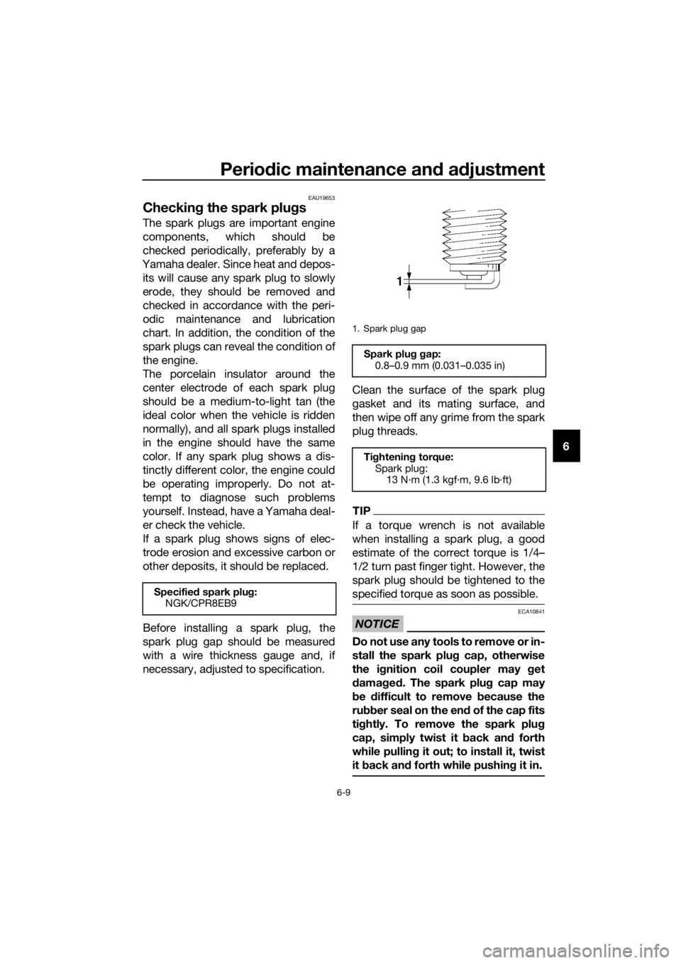
Before installing a spark plug, the
spark plug gap should be measured
with a wire thickness gauge and, if
necessary, adjusted to specification. Clean the surface of the spark plug
gasket and its mating surface, and
then wipe off any grime from the spark
plug threads.
TIP
If a torque wrench is not available
when installing a spark plug, a good
estimate of the correct torque is 1/4–
1/2 turn past finger tight. However, the
spark plug should be tightened to the
specified torque as soon as possible.
NOTICE
ECA10841
Do not use any tools to remove or in-
stall the spark plu
g cap, otherwise
the i gnition coil coupler may get
d amag ed . The spark plu g cap may
b e difficult to remove because the
ru bber seal on the en d of the cap fits
ti g htly. To remove the spark plu g
cap, simply twist it back an d forth
while pullin g it out; to install it, twist
it back an d forth while pushin g it in.
Specified spark plu g:
NGK/CPR8EB9
1. Spark plug gap
Spark plu g g ap:
0.8–0.9 mm (0.031–0.035 in)
Ti ghtenin g torque:
Spark plug: 13 N·m (1.3 kgf·m, 9.6 lb·ft)
UBP9E1E0.book Page 9 Friday, September 7, 2018 10:01 AM
Page 76 of 122
Periodic maintenance an d a djustment
6-10
6
EAU79401
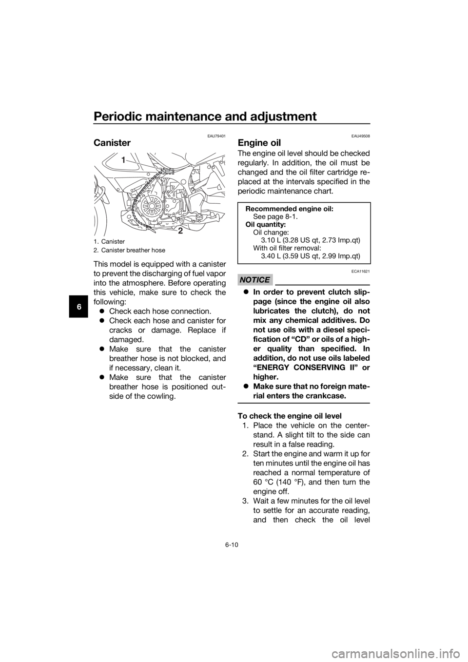
Canister
This model is equipped with a canister
to prevent the discharging of fuel vapor
into the atmosphere. Before operating
this vehicle, make sure to check the
following:
Check each hose connection.
Check each hose and canister for
cracks or damage. Replace if
damaged.
Make sure that the canister
breather hose is not blocked, and
if necessary, clean it.
Make sure that the canister
breather hose is positioned out-
side of the cowling.
EAU49508
Engine oil
The engine oil level should be checked
regularly. In addition, the oil must be
changed and the oil filter cartridge re-
placed at the intervals specified in the
periodic maintenance chart.
NOTICE
ECA11621
In or der to prevent clutch slip-
pa ge (since the en gine oil also
lu bricates the clutch), do not
mix any chemical add itives. Do
not use oils with a d iesel speci-
fication of “CD” or oils of a hi gh-
er quality than specified . In
a ddition, do not use oils la bele d
“ENERGY CONSERVING II” or
hi gher.
Make sure that no forei gn mate-
rial enters the crankcase.
To check the en gine oil level
1. Place the vehicle on the center- stand. A slight tilt to the side can
result in a false reading.
2. Start the engine and warm it up for ten minutes until the engine oil has
reached a normal temperature of
60 °C (140 °F), and then turn the
engine off.
3. Wait a few minutes for the oil level to settle for an accurate reading,
and then check the oil level
1. Canister
2. Canister breather hose
2
1
Recommen ded en gine oil:
See page 8-1.
Oil quantity: Oil change:3.10 L (3.28 US qt, 2.73 Imp.qt)
With oil filter removal: 3.40 L (3.59 US qt, 2.99 Imp.qt)
UBP9E1E0.book Page 10 Friday, September 7, 2018 10:01 AM