clock YAMAHA XT500E 2000 Owners Manual
[x] Cancel search | Manufacturer: YAMAHA, Model Year: 2000, Model line: XT500E, Model: YAMAHA XT500E 2000Pages: 96, PDF Size: 4.23 MB
Page 15 of 96

3-1
ON
OFF
LOCK
P
EAU00029
Main switch/steering lockThe main switch controls the ignition
and lighting systems. Its operation is
described below.
EAU00036
ON
Electrical circuits are switched on.
The engine can be started. The key
cannot be removed in this position.
EAU00038
OFF
All electrical circuits are switched off.
The key can be removed in this posi-
tion.
EAU00042
LOCK
The steering is locked in this position
and all electrical circuits are switched
off.
The key can be removed in this posi-
tion.
To lock the steering, turn the handle-
bars all the way to the left. With the
key at ÒOFFÓ, push it into the main
switch and release it, turn it counter-
clockwise to ÒLOCKÓ and remove it.
To release the lock, turn the key to
"OFF".
EW000016
wNever turn the key to ÒOFFÓ or
ÒLOCKÓ when the motorcycle is
moving. The electrical circuits will
be switched off which may result
in loss of control or an accident.
Be sure the motorcycle is stopped
before turning the key to ÒOFFÓ or
ÒLOCKÓ.
EAU01590
. .
(Parking)
The steering is locked in this position,
and the taillight and auxiliary light
come on but all other circuits are off.
The key can be removed in this posi-
tion.
To use the parking position, first lock
the steering, then turn the key to Ò
.
Ó.
Do not use this position for an
extended length of time as the bat-
tery may discharge.
EAU00027
INSTRUMENT AND CONTROL FUNCTIONS
1
23
4
5
6
7
8
9
12
1. Push2.Turn
4PT-9-E6 (ENG) 1~5 12/27/00 1:28 PM Page 14
Page 20 of 96

3-6
INSTRUMENT AND CONTROL FUNCTIONS
1
23
4
5
6
7
8
9
2
1
EAU00177
Fuel tank capTo open
Insert the key and turn it 1/4 turn
counterclockwise. Turn the cap 1/3
turn counterclockwise and remove it
from the tank.
To close
Put the cap in the filler neck and turn
it 1/3 turn clockwise. Lock the cap by
turning the key 1/4 turn clockwise,
and remove the key.1.Unlock
2.Open
NOTE:
The tank cap cannot be reinstalled
unless it is unlocked. The key must
remain in the cap until the cap is
properly installed and locked onto the
fuel tank.
EW000023
wBe sure the cap is properly
installed and locked in place
before riding the motorcycle.
2
1
1.Filler tube
2.Fuel level
EAU01183
FuelMake sure there is sufficient fuel in
the tank. Fill the fuel tank to the bot-
tom of the filler tube as shown in the
illustration.
EW000130
wDo not overfill the fuel tank. Avoid
spilling fuel on the hot engine. Do
not fill the fuel tank above the bot-
tom of the filler tube or it may
overflow when the fuel heats up
later and expands.
4PT-9-E6 (ENG) 1~5 12/27/00 1:28 PM Page 19
Page 70 of 96

6-30
PERIODIC MAINTENANCE AND MINOR REPAIR
1
2
3
4
56
7
8
9
2
1
3.Remove the connectors and the
bulb holder cover.1.Connector (´3)
2.Bulb holder cover
5.Put a new bulb into position and
secure it in place with the bulb
holder.
EC000105
cCAvoid touching the glass part of a
bulb. Keep it free from oil; other-
wise, the transparency of the
glass, life of the bulb, and lumi-
nous flux will be adversely affect-
ed. If oil gets on a bulb, thoroughly
clean it with a cloth moistened
with alcohol or lacquer thinner.
4.Turn the bulb holder counter-
clockwise to remove it and
remove the defective bulb.
EW000119
wKeep flammable products and your
hands away from a bulb while it is
on, as it is hot. Do not touch a bulb
until it cools down.
1
1.Bulb holder
1
1.DonÕt touch
4PT-9-E6 (ENG) 6 12/27/00 1:29 PM Page 31
Page 71 of 96

6-31
PERIODIC MAINTENANCE AND MINOR REPAIR
1
2
3
4
56
7
8
9
EAU01095
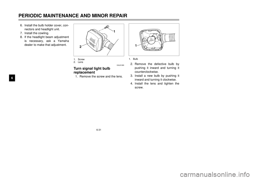
Turn signal light bulb
replacement1.Remove the screw and the lens.2.Remove the defective bulb by
pushing it inward and turning it
counterclockwise.
3.Install a new bulb by pushing it
inward and turning it clockwise.
4.Install the lens and tighten the
screw.
1
2
1.Screw
2.Lens
1
1.Bulb
6.Install the bulb holder cover, con-
nectors and headlight unit.
7.Install the cowling.
8.If the headlight beam adjustment
is necessary, ask a Yamaha
dealer to make that adjustment.
4PT-9-E6 (ENG) 6 12/27/00 1:29 PM Page 32
Page 72 of 96

6-32
PERIODIC MAINTENANCE AND MINOR REPAIR
1
2
3
4
56
7
8
9
EAU01579
Supporting the motorcycleSince the Yamaha XT500E/XT600E
has no centerstand, follow these pre-
cautions when removing the front and
rear wheel or performing other main-
tenance requiring the motorcycle to
stand upright. Check that the motor-
cycle is in a stable and level position
before starting any maintenance. A
strong wooden box can be placed
under the engine for added stability.
Front wheel service
To stabilize the rear of the motorcy-
cle, either use a motorcycle stand or
place a motorcycle jack under the
frame in front of the rear wheel to
prevent it from moving from side to
side. Then use a motorcycle stand to
elevate the front wheel off of the
ground.
EAU01623
Taillight bulb replacement1.Remove the screws and the
lens.
21
1.Screw (´2)
2.Lens
2.Remove the defective bulb by
pushing it inward and turning it
counterclockwise.
3.Install a new bulb by pushing it
inward and turning it clockwise.
4.Install the lens and tighten the
screws.
EC000108
cCDo not over-tighten the screws as
the lens may break.
1
1.Bulb
4PT-9-E6 (ENG) 6 12/27/00 1:29 PM Page 33