steering YAMAHA XV1600A 2000 Owners Manual
[x] Cancel search | Manufacturer: YAMAHA, Model Year: 2000, Model line: XV1600A, Model: YAMAHA XV1600A 2000Pages: 95, PDF Size: 19.02 MB
Page 13 of 95
DESCRIPTION
2-3
2
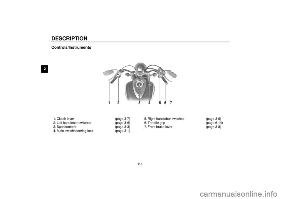
Controls/Instruments1. Clutch lever (page 3-7)
2. Left handlebar switches (page 3-6)
3. Speedometer (page 3-3)
4. Main switch/steering lock (page 3-1)5. Right handlebar switches (page 3-6)
6. Throttle grip (page 6-14)
7. Front brake lever (page 3-8)
E_5ja_Description.fm Page 3 Saturday, October 16, 1999 10:10 AM
Page 14 of 95
3
INSTRUMENT AND CONTROL FUNCTIONS
Main switch/steering lock ...................................... 3-1
Indicator lights ...................................................... 3-2
Speedometer ........................................................ 3-3
Fuel gauge ............................................................ 3-4
Diagnosis device................................................... 3-4
Antitheft alarm (optional) ...................................... 3-4
Digital clock........................................................... 3-5
Handlebar switches .............................................. 3-6
Clutch lever ........................................................... 3-7
Shift pedal ............................................................. 3-7
Front brake lever ................................................... 3-8
Rear brake pedal .................................................. 3-8Fuel tank cap ....................................................... 3-9
Fuel ...................................................................... 3-9
Fuel tank breather hose ..................................... 3-10
Fuel cock ............................................................ 3-11
Starter (choke) knob .......................................... 3-12
Steering lock ...................................................... 3-12
Rider seat........................................................... 3-13
Helmet holder..................................................... 3-13
Adjusting rear shock absorber preload .............. 3-14
Sidestand ........................................................... 3-15
Sidestand/clutch switch operation check............ 3-16
E_5ja_FunctionsTOC.fm Page 1 Saturday, October 16, 1999 10:10 AM
Page 15 of 95
3-1
3
EAU00027
3-INSTRUMENT AND CONTROL FUNCTIONS
EAU00029*
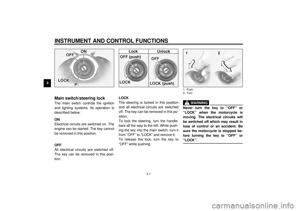
Main switch/steering lockThe main switch controls the ignition
and lighting systems. Its operation is
described below.
EAU00036
ON
Electrical circuits are switched on. The
engine can be started. The key cannot
be removed in this position.
EAU00038
OFF
All electrical circuits are switched off.
The key can be removed in this posi-
tion.
EAU00040
LOCK
The steering is locked in this position
and all electrical circuits are switched
off. The key can be removed in this po-
sition.
To lock the steering, turn the handle-
bars all the way to the left. While push-
ing the key into the main switch, turn it
from “OFF” to “LOCK” and remove it.
To release the lock, turn the key to
“OFF” while pushing.
EW000016
WARNING
@ Never turn the key to “OFF” or
“LOCK” when the motorcycle is
moving. The electrical circuits will
be switched off which may result in
loss of control or an accident. Be
sure the motorcycle is stopped be-
fore turning the key to “OFF” or
“LOCK”. @1. Push
2. Turn
E_5ja_Functions.fm Page 1 Saturday, October 16, 1999 10:10 AM
Page 16 of 95
INSTRUMENT AND CONTROL FUNCTIONS
3-2
3
EAU01590
(Parking)
The steering is locked in this position,
and the taillight and auxiliary light come
on but all other circuits are off. The key
can be removed in this position.
To use the parking position, first lock
the steering, then turn the key to “ ”.
Do not use this position for an extend-
ed length of time as the battery may
discharge.
EAU00056
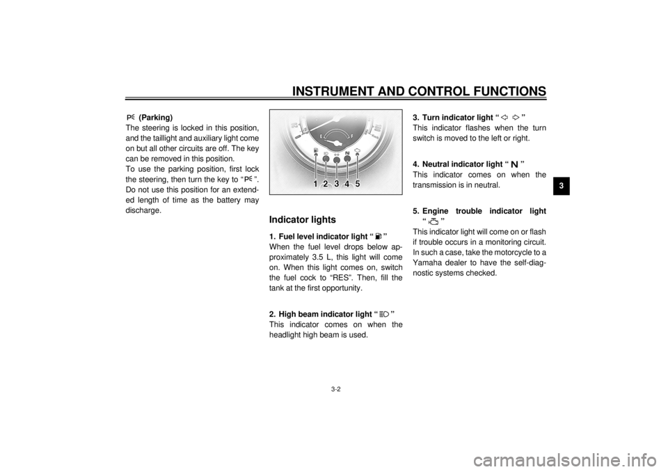
Indicator lights
EAU00079
1. Fuel level indicator light “ ”
When the fuel level drops below ap-
proximately 3.5 L, this light will come
on. When this light comes on, switch
the fuel cock to “RES”. Then, fill the
tank at the first opportunity.
EAU00063
2. High beam indicator light “ ”
This indicator comes on when the
headlight high beam is used.
EAU00057
3. Turn indicator light “ ”
This indicator flashes when the turn
switch is moved to the left or right.
EAU00061
4. Neutral indicator light “ ”
This indicator comes on when the
transmission is in neutral.
EAU00091
5. Engine trouble indicator light
“”
This indicator light will come on or flash
if trouble occurs in a monitoring circuit.
In such a case, take the motorcycle to a
Yamaha dealer to have the self-diag-
nostic systems checked.
E_5ja_Functions.fm Page 2 Saturday, October 16, 1999 10:10 AM
Page 26 of 95
INSTRUMENT AND CONTROL FUNCTIONS
3-12
3
EAU03032
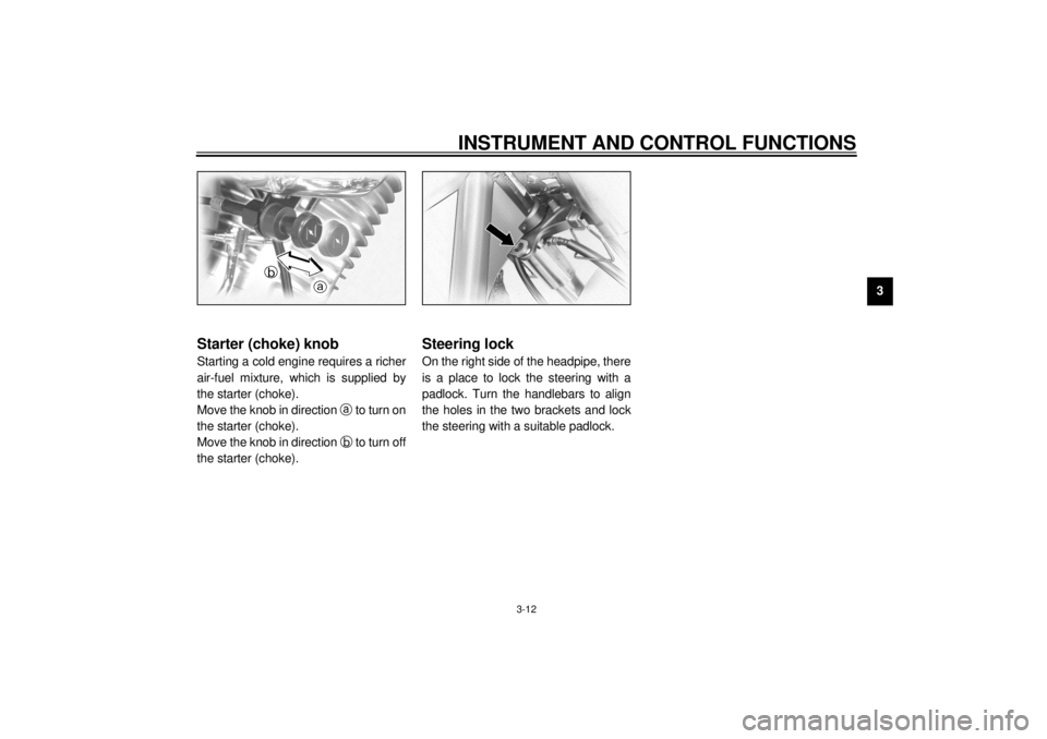
Starter (choke) knobStarting a cold engine requires a richer
air-fuel mixture, which is supplied by
the starter (choke).
Move the knob in direction
a to turn on
the starter (choke).
Move the knob in direction
b to turn off
the starter (choke).
EAU01214*
Steering lockOn the right side of the headpipe, there
is a place to lock the steering with a
padlock. Turn the handlebars to align
the holes in the two brackets and lock
the steering with a suitable padlock.
E_5ja_Functions.fm Page 12 Saturday, October 16, 1999 10:10 AM
Page 44 of 95
6
PERIODIC MAINTENANCE AND MINOR REPAIR
Tool kit................................................................... 6-1
Periodic maintenance and lubrication ................... 6-3
Spark plug inspection ........................................... 6-6
Engine oil .............................................................. 6-7
Transfer case oil .................................................. 6-10
Air filter ............................................................... 6-11
Carburetor adjustment ........................................ 6-13
Idle speed adjustment ........................................ 6-13
Throttle cable free play inspection ...................... 6-14
Valve clearance adjustment ................................ 6-14
Tires .................................................................... 6-15
Wheels ................................................................ 6-17
Clutch lever free play adjustment........................ 6-17
Front brake lever free play adjustment ................ 6-18
Rear brake pedal height adjustment ................... 6-19
Brake light switch adjustment ............................. 6-19
Checking the front and rear brake pads.............. 6-20Inspecting the brake fluid level ........................... 6-21
Brake fluid replacement ..................................... 6-22
Drive belt slack check ........................................ 6-22
Drive belt slack adjustment ................................ 6-23
Brake and shift pedal lubrication ........................ 6-24
Brake and clutch lever lubrication ...................... 6-25
Sidestand lubrication.......................................... 6-25
Front fork inspection ........................................... 6-26
Steering inspection ............................................ 6-26
Wheel bearings .................................................. 6-27
Battery................................................................ 6-27
Fuse replacement .............................................. 6-28
Headlight bulb replacement ............................... 6-29
Turn signal and tail/brake light bulb
replacement ..................................................... 6-31
Troubleshooting .................................................. 6-31
Troubleshooting chart ......................................... 6-32
E_5ja_PeriodicTOC.fm Page 1 Saturday, October 16, 1999 10:12 AM
Page 48 of 95

PERIODIC MAINTENANCE AND MINOR REPAIR
6-4
6
11
*Wheel bearings• Check bearing for looseness or damage.
• Replace if necessary. ÖÖ
12*Swingarm• Check swingarm pivoting point for play.
• Correct if necessary.
• Lubricate with molybdenum disulfide grease every 24,000 km or
24 months (whichever comes first).ÖÖ
13*Drive belt• Check belt tension.
• Adjust if necessary. Make sure that the rear wheel is properly
aligned.ÖEvery 4,000 km
14*Steering bearings• Check bearing play and steering for roughness.
• Correct accordingly.
• Lubricate with lithium soap base grease every 24,000 km
or 24 months (whichever comes first).ÖÖ
15*Chassis fasteners• Make sure that all nuts, bolts and screws are properly tightened.
• Tighten if necessary.ÖÖ
16 Sidestand• Check operation.
• Lubricate and repair if necessary.ÖÖ
17*Sidestand switch• Check operation.
• Replace if necessary.ÖÖÖ
18*Front fork• Check operation and for oil leakage.
• Correct accordingly.ÖÖ
19*Rear shock absorber
assembly• Check operation and shock absorber for oil leakage.
• Replace shock absorber assembly if necessary. ÖÖ
20*Rear suspension relay
arm and connecting arm
pivoting points• Check operation.
• Lubricate with molybdenum disulfide grease every 24,000 km or
24 months (whichever comes first).ÖÖ
21*Carburetor• Check engine idling speed and starter operation.
• Adjust if necessary.ÖÖÖ NO. ITEM CHECKS AND MAINTENANCE JOBSINITIAL
(1,000 km)EVERY
6,000 km
or
6 months
(whichever
comes first)12,000 km
or
12 months
(whichever
comes first)
E_5ja_Periodic.fm Page 4 Saturday, October 16, 1999 10:12 AM
Page 70 of 95
PERIODIC MAINTENANCE AND MINOR REPAIR
6-26
6
EAU02939
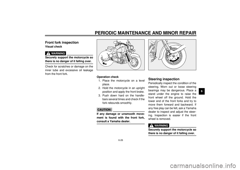
Front fork inspectionVisual check
EW000115
WARNING
@ Securely support the motorcycle so
there is no danger of it falling over. @Check for scratches or damage on the
inner tube and excessive oil leakage
from the front fork.
Operation check
1. Place the motorcycle on a level
place.
2. Hold the motorcycle in an upright
position and apply the front brake.
3. Push down hard on the handle-
bars several times and check if the
fork rebounds smoothly.
EC000098
CAUTION:@ If any damage or unsmooth move-
ment is found with the front fork,
consult a Yamaha dealer. @
EAU00794
Steering inspectionPeriodically inspect the condition of the
steering. Worn out or loose steering
bearings may be dangerous. Place a
stand under the engine to raise the
front wheel off the ground. Hold the
lower end of the front forks and try to
move them forward and backward. If
any free play can be felt, ask a Yamaha
dealer to inspect and adjust the steer-
ing. Inspection is easier if the front
wheel is removed.
EW000115
WARNING
@ Securely support the motorcycle so
there is no danger of it falling over. @
E_5ja_Periodic.fm Page 26 Saturday, October 16, 1999 10:12 AM
Page 91 of 95
9-1
9
EAU01039
9-CONSUMER INFORMATION
EAU02944
Identification number recordsRecord the key identification number,
vehicle identification number and mod-
el label information in the spaces pro-
vided for assistance when ordering
spare parts from a Yamaha dealer or
for reference in case the vehicle is sto-
len.
1. KEY IDENTIFICATION NUMBER:CA-02E2. VEHICLE IDENTIFICATION
NUMBER:CA-02E3. MODEL LABEL INFORMATION:CA-01EEAU01041
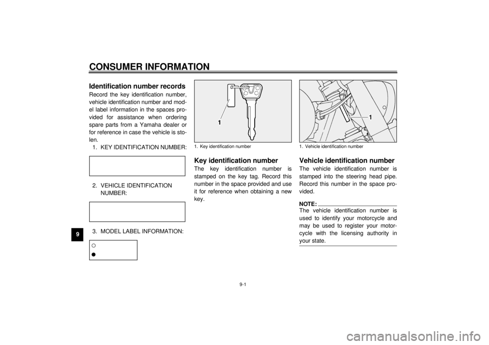
Key identification numberThe key identification number is
stamped on the key tag. Record this
number in the space provided and use
it for reference when obtaining a new
key.
EAU01043
Vehicle identification numberThe vehicle identification number is
stamped into the steering head pipe.
Record this number in the space pro-
vided.NOTE:@ The vehicle identification number is
used to identify your motorcycle and
may be used to register your motor-
cycle with the licensing authority in
your state. @
1. Key identification number
1. Vehicle identification number
E_5ja_Consumer.fm Page 1 Saturday, October 16, 1999 10:19 AM
Page 93 of 95
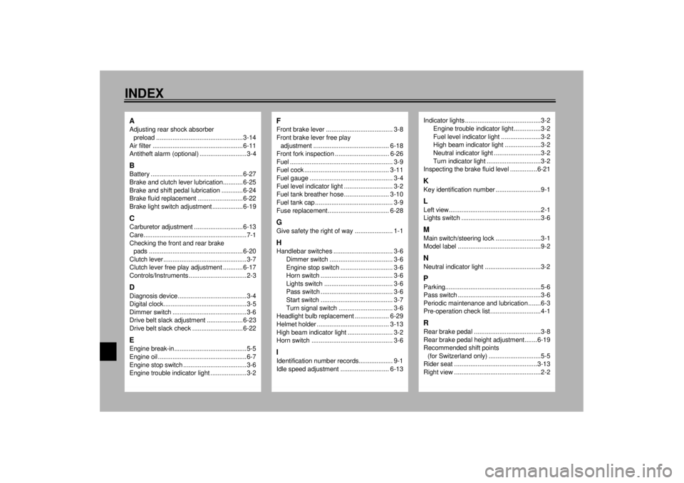
10-INDEXAAdjusting rear shock absorber
preload ................................................ 3-14
Air filter .................................................. 6-11
Antitheft alarm (optional) ..........................3-4BBattery ................................................... 6-27
Brake and clutch lever lubrication........... 6-25
Brake and shift pedal lubrication ............ 6-24
Brake fluid replacement ......................... 6-22
Brake light switch adjustment ................. 6-19CCarburetor adjustment ........................... 6-13
Care.........................................................7-1
Checking the front and rear brake
pads .................................................... 6-20
Clutch lever ..............................................3-7
Clutch lever free play adjustment ........... 6-17
Controls/Instruments ................................2-3DDiagnosis device......................................3-4
Digital clock..............................................3-5
Dimmer switch .........................................3-6
Drive belt slack adjustment .................... 6-23
Drive belt slack check ............................ 6-22EEngine break-in........................................5-5
Engine oil .................................................6-7
Engine stop switch ...................................3-6
Engine trouble indicator light ....................3-2
FFront brake lever ..................................... 3-8
Front brake lever free play
adjustment .......................................... 6-18
Front fork inspection .............................. 6-26
Fuel ......................................................... 3-9
Fuel cock ............................................... 3-11
Fuel gauge .............................................. 3-4
Fuel level indicator light ........................... 3-2
Fuel tank breather hose ......................... 3-10
Fuel tank cap ........................................... 3-9
Fuse replacement.................................. 6-28GGive safety the right of way ..................... 1-1HHandlebar switches ................................. 3-6
Dimmer switch ................................... 3-6
Engine stop switch ............................. 3-6
Horn switch ........................................ 3-6
Lights switch ...................................... 3-6
Pass switch ........................................ 3-6
Start switch ........................................ 3-7
Turn signal switch .............................. 3-6
Headlight bulb replacement ................... 6-29
Helmet holder ........................................ 3-13
High beam indicator light ......................... 3-2
Horn switch ............................................. 3-6IIdentification number records................... 9-1
Idle speed adjustment ........................... 6-13
Indicator lights ..........................................3-2
Engine trouble indicator light ...............3-2
Fuel level indicator light ......................3-2
High beam indicator light ....................3-2
Neutral indicator light ..........................3-2
Turn indicator light ..............................3-2
Inspecting the brake fluid level ...............6-21KKey identification number .........................9-1LLeft view...................................................2-1
Lights switch ............................................3-6MMain switch/steering lock .........................3-1
Model label ..............................................9-2NNeutral indicator light ...............................3-2PParking.....................................................5-6
Pass switch ..............................................3-6
Periodic maintenance and lubrication .......6-3
Pre-operation check list ............................4-1RRear brake pedal .....................................3-8
Rear brake pedal height adjustment.......6-19
Recommended shift points
(for Switzerland only) .............................5-5
Rider seat ..............................................3-13
Right view ................................................2-2
E_5jaIX.fm Page 1 Saturday, October 16, 1999 10:19 AM