brake YAMAHA XV1600A 2001 Owner's Manual
[x] Cancel search | Manufacturer: YAMAHA, Model Year: 2001, Model line: XV1600A, Model: YAMAHA XV1600A 2001Pages: 104, PDF Size: 20.37 MB
Page 74 of 104

PERIODIC MAINTENANCE AND MINOR REPAIR
6-29
6
EAU03164
Checking and lubricating the
brake and clutch levers The operation of the brake and clutch
levers should be checked before each
ride, and the lever pivots should be lu-
bricated if necessary.
Recommended lubricant:
Lithium-soap-based grease
(all-purpose grease)
E_5JA.book Page 29 Wednesday, September 13, 2000 6:06 PM
Page 75 of 104

PERIODIC MAINTENANCE AND MINOR REPAIR
6-30
6
EAU03165
Checking and lubricating the
sidestand The operation of the sidestand should
be checked before each ride, and the
sidestand pivot and metal-to-metal
contact surfaces should be lubricated if
necessary.
EW000113
WARNING
@ If the sidestand does not move up
and down smoothly, have a Yamaha
dealer check or repair it. @
EAU02939
Checking the front fork The condition and operation of the front
fork must be checked as follows at the
intervals specified in the periodic main-
tenance and lubrication chart.
To check the condition
EW000115
WARNING
@ Securely support the motorcycle so
that there is no danger of it falling
over. @Check the inner tubes for scratches,
damage and excessive oil leakage.To check the operation
1. Place the motorcycle on a level
surface and hold it in an upright
position.
2. While applying the front brake,
push down hard on the handle-
bars several times to check if the
front fork compresses and re-
bounds smoothly.
EC000098
CAUTION:@ If any damage is found or the front
fork does not operate smoothly,
have a Yamaha dealer check or re-
pair it. @
Recommended lubricant:
Lithium-soap-based grease
(all-purpose grease)
E_5JA.book Page 30 Wednesday, September 13, 2000 6:06 PM
Page 82 of 104
PERIODIC MAINTENANCE AND MINOR REPAIR
6-37
6
EAU00855
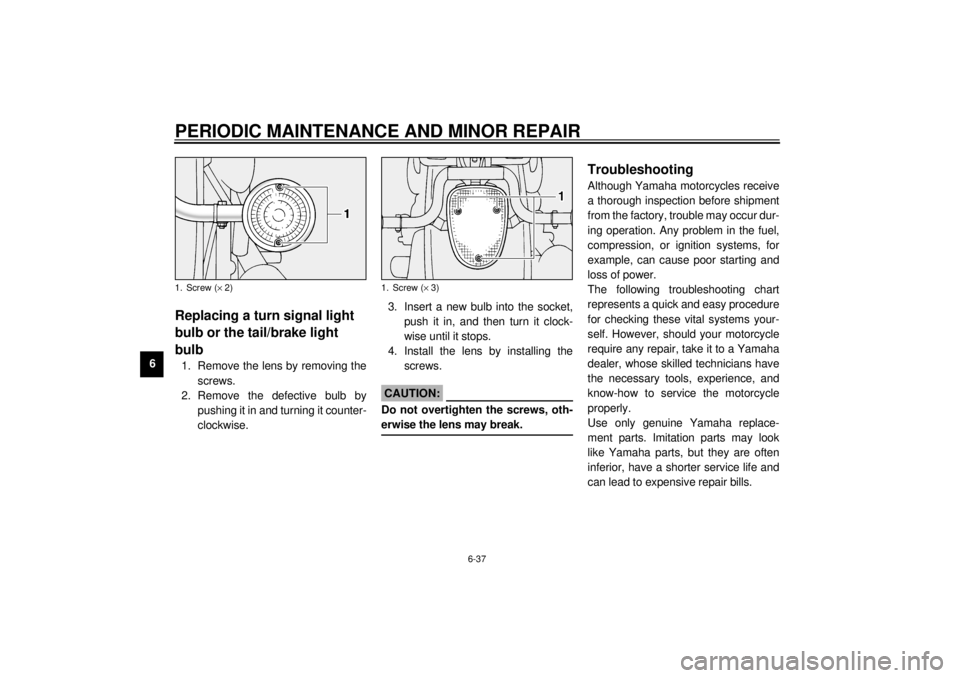
Replacing a turn signal light
bulb or the tail/brake light
bulb 1. Remove the lens by removing the
screws.
2. Remove the defective bulb by
pushing it in and turning it counter-
clockwise.3. Insert a new bulb into the socket,
push it in, and then turn it clock-
wise until it stops.
4. Install the lens by installing the
screws.
EC000108
CAUTION:@ Do not overtighten the screws, oth-
erwise the lens may break. @
EAU01008
Troubleshooting Although Yamaha motorcycles receive
a thorough inspection before shipment
from the factory, trouble may occur dur-
ing operation. Any problem in the fuel,
compression, or ignition systems, for
example, can cause poor starting and
loss of power.
The following troubleshooting chart
represents a quick and easy procedure
for checking these vital systems your-
self. However, should your motorcycle
require any repair, take it to a Yamaha
dealer, whose skilled technicians have
the necessary tools, experience, and
know-how to service the motorcycle
properly.
Use only genuine Yamaha replace-
ment parts. Imitation parts may look
like Yamaha parts, but they are often
inferior, have a shorter service life and
can lead to expensive repair bills.
1. Screw (´ 2)
1. Screw (´ 3)
E_5JA.book Page 37 Wednesday, September 13, 2000 6:06 PM
Page 87 of 104

MOTORCYCLE CARE AND STORAGE
7-2
7
l
Do not use any harsh chemical
products on plastic parts. Be
sure to avoid using cloths or
sponges which have been in
contact with strong or abrasive
cleaning products, solvent or
thinner, fuel (gasoline), rust re-
movers or inhibitors, brake flu-
id, antifreeze or electrolyte.
l
Do not use high-pressure wash-
ers or steam-jet cleaners since
they cause water seepage and
deterioration in the following ar-
eas: seals (of wheel and swing-
arm bearings, fork and brakes),
electric components (couplers,
connectors, instruments, switch-
es and lights), breather hoses
and vents.
l
For motorcycles equipped with
a windshield: Do not use strong
cleaners or hard sponges as
they will cause dulling or
scratching. Some cleaning
compounds for plastic may
leave scratches on the wind-
shield. Test the product on a
small hidden part of the wind-
shield to make sure that it does
not leave any marks. If the wind-
shield is scratched, use a quali-
ty plastic polishing compound
after washing.
@
After normal useRemove dirt with warm water, a mild
detergent, and a soft, clean sponge,
and then rinse thoroughly with clean
water. Use a toothbrush or bottlebrush
for hard-to-reach areas. Stubborn dirt
and insects will come off more easily if
the area is covered with a wet cloth for
a few minutes before cleaning.
E_5JA.book Page 2 Wednesday, September 13, 2000 6:06 PM
Page 88 of 104

MOTORCYCLE CARE AND STORAGE
7-3
7After riding in the rain, near the sea or
on salt-sprayed roadsSince sea salt or salt sprayed on roads
during winter are extremely corrosive in
combination with water, carry out the
following steps after each ride in the
rain, near the sea or on salt-sprayed
roads.NOTE:@ Salt sprayed on roads in the winter may
remain well into spring. @1. Clean the motorcycle with cold
water and a mild detergent, after
the engine has cooled down.
ECA00012
CAUTION:@ Do not use warm water since it in-
creases the corrosive action of the
salt. @2. After drying the motorcycle, apply
a corrosion protection spray on all
metal, including chrome- and nick-
el-plated, surfaces to prevent cor-
rosion.After cleaning
1. Dry the motorcycle with a chamois
or an absorbing cloth.
2. Use a chrome polish to shine
chrome, aluminum and stainless-
steel parts, including the exhaust
system. (Even the thermally in-
duced discoloring of stainless-
steel exhaust systems can be re-
moved through polishing.)
3. To prevent corrosion, it is recom-
mended to apply a corrosion pro-
tection spray on all metal,
including chrome- and nickel-plat-
ed, surfaces.
4. Use spray oil as a universal clean-
er to remove any remaining dirt.
5. Touch up minor paint damage
caused by stones, etc.
6. Wax all painted surfaces.
7. Let the motorcycle dry completely
before storing or covering it.
EWA00001
WARNING
@ l
Make sure that there is no oil or
wax on the brakes or tires. If
necessary, clean the brake
discs and brake linings with a
regular brake disc cleaner or ac-
etone, and wash the tires with
warm water and a mild deter-
gent.
l
Before operating the motor-
cycle test its braking perfor-
mance and cornering behavior.
@
E_5JA.book Page 3 Wednesday, September 13, 2000 6:06 PM
Page 94 of 104

SPECIFICATIONS
8-3
8
Maximum load* 196 kg
Tire air pressure (measured on
cold tires)
Up to 90 kg*
Front 250 kPa (2.50 kg/cm
2, 2.50 bar)
Rear 250 kPa (2.50 kg/cm2, 2.50 bar)
90 kg–maximum*
Front 250 kPa (2.50 kg/cm2, 2.50 bar)
Rear 280 kPa (2.80 kg/cm2, 2.80 bar)
* Total weight of rider, passenger, cargo and accessories
Wheels
Front
Type Spoke wheel
Size 16 ´ MT 3.00
Rear
Type Spoke wheel
Size 16 ´ MT 3.50
Brakes
Front
Type Dual disc brake
Operation Right hand
Fluid DOT 4Rear
Type Single disc brake
Operation Right foot
Fluid DOT 4
Suspension
Front Telescopic fork
Rear Swingarm (link suspension)
Spring/shock absorber
Front Coil spring / oil damper
Rear Coil spring / gas-oil damper
Wheel travel
Front 140 mm
Rear 110 mm
Electrical
Ignition system Transistorized coil ignition
(digital)
Charging system
Type A.C. magneto
Standard output 14 V, 21 A @ 5,000 r/min
Battery
Type YTX20L-BS
Voltage, capacity 12 V, 18 Ah
E_5JA.book Page 3 Wednesday, September 13, 2000 6:06 PM
Page 95 of 104

SPECIFICATIONS
8-4
8
Headlight typeQuar tz bulb (halogen)
Bulb voltage, wattage ´ quantity
Headlight 12 V, 60/55 W ´ 1
Tail/brake light 12 V, 5/21 W ´ 1
Turn signal lights 12 V, 21 W ´ 4
Auxiliary light 12 V, 4 W ´ 1
Meter lighting 14 V, 0.6 W ´ 4
Neutral indicator light 12 V, 1 W ´ 1
High beam indicator light 12 V, 1 W ´ 1
Turn indicator light 12 V, 1 W ´ 1
Fuel level warning light LED ´ 1
Engine trouble warning light LED ´ 1
Fuses
Main fuse 30 A
Ignition fuse 15 A
Signaling system fuse 10 A
Headlight fuse 15 A
Carburetor heater fuse 10 A
Odometer fuse 5 A
E_5JA.book Page 4 Wednesday, September 13, 2000 6:06 PM
Page 100 of 104
10-INDEXAAir filter element, cleaning ...................... 6-13
Anti-theft alarm ........................................3-4BBattery ................................................... 6-32
Brake and clutch levers, checking and
lubricating ............................................ 6-29
Brake and shift pedals, checking and
lubricating ............................................ 6-28
Brake fluid, changing ............................. 6-26
Brake fluid level, checking...................... 6-25
Brake lever...............................................3-8
Brake lever free play, adjusting .............. 6-22
Brake light switch (rear), adjusting ......... 6-23
Brake pads, checking............................. 6-23
Brake pedal..............................................3-8
Brake pedal position, adjusting .............. 6-22CCarburetor, adjusting ............................. 6-16
Care.........................................................7-1
Clock .......................................................3-5
Clutch lever ..............................................3-7
Clutch lever free play, adjusting ............. 6-21
Conversion table ......................................8-5DDimmer switch .........................................3-6
Drive belt slack ...................................... 6-26
Adjusting .......................................... 6-27
Checking .......................................... 6-26
EEngine break-in ....................................... 5-5
Engine oil and oil filter cartridge ............... 6-8
Engine stop switch................................... 3-6
Engine trouble warning light .................... 3-2FFront fork, checking ............................... 6-30
Fuel ......................................................... 3-9
Fuel cock ............................................... 3-11
Fuel consumption, tips for reducing ......... 5-4
Fuel gauge .............................................. 3-4
Fuel level warning light ............................ 3-2
Fuel tank breather hose ......................... 3-10
Fuel tank cap ........................................... 3-9
Fuses, replacing .................................... 6-33HHandlebar switches ................................. 3-6
Headlight bulb, replacing ....................... 6-35
Helmet holder ........................................ 3-13
High beam indicator light ......................... 3-2
Horn switch ............................................. 3-6IIdentification numbers ............................. 9-1
Idling speed, adjusting ........................... 6-16
Ignition circuit cut-off system.................. 3-16
Indicator and warning lights ..................... 3-2KKey identification number ........................ 9-1
LLight switch ..............................................3-6MMain switch/steering lock .........................3-1
Model label ..............................................9-2NNeutral indicator light ...............................3-2PPanel, removing and installing..................6-6
Parking.....................................................5-6
Part locations ...........................................2-1
Pass switch ..............................................3-6
Periodic maintenance and
lubrication chart ....................................... 6-3
Pre-operation check list ............................4-1RRider seat ..............................................3-12SSafety information ....................................1-1
Self-diagnosis device ...............................3-4
Shifting .....................................................5-3
Shift pedal ................................................3-7
Shift points (for Switzerland only) .............5-4
Shock absorber assembly, adjusting ......3-14
Sidestand ...............................................3-15
Sidestand, checking and lubricating .......6-30
Spark plugs, checking ..............................6-7
Specifications ...........................................8-1
Speedometer unit.....................................3-3
E_5JA.book Page 1 Wednesday, September 13, 2000 6:06 PM
Page 101 of 104
INDEX
Starter (choke) knob .............................. 3-12
Starting a warm engine ............................ 5-3
Starting the engine .................................. 5-1
Start switch .............................................. 3-7
Steering, checking ................................. 6-31
Steering, locking with a padlock............. 3-12
Storage.................................................... 7-4TThrottle cable free play, adjusting .......... 6-17
Tires ...................................................... 6-17
Tool kit..................................................... 6-1
Transfer case oil .................................... 6-12
Troubleshooting..................................... 6-37
Troubleshooting chart ............................ 6-38
Turn signal indicator light ......................... 3-2
Turn signal light or tail/brake light bulb,
replacing ............................................. 6-37
Turn signal switch .................................... 3-6VValve clearance, adjusting ..................... 6-17
Vehicle identification number ................... 9-1WWheel bearings, checking...................... 6-31
Wheels .................................................. 6-20
E_5JA.book Page 2 Wednesday, September 13, 2000 6:06 PM