high beam YAMAHA XV535 2000 Owners Manual
[x] Cancel search | Manufacturer: YAMAHA, Model Year: 2000, Model line: XV535, Model: YAMAHA XV535 2000Pages: 87, PDF Size: 17.84 MB
Page 15 of 87

L
3-1
INSTRUMENT AND CONTROL FUNCTIONS
/Net/layout8/layout_G2/work/Imai_work/OM-PS/AA9149_XV535-E6/English/E-3.frame
EAU00027
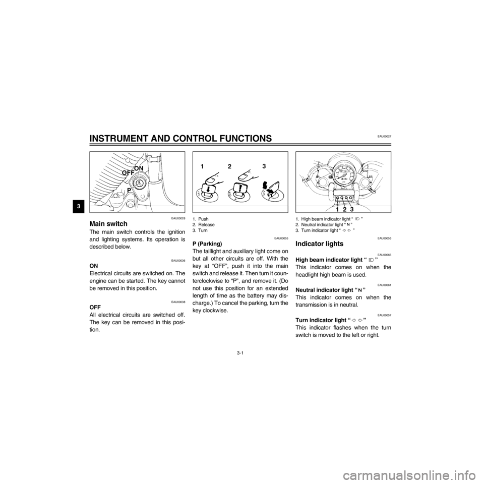
EAU00028
Main switch
The main switch controls the ignition
and lighting systems. Its operation is
described below.
EAU00036
ON
Electrical circuits are switched on. The
engine can be started. The key cannot
be removed in this position.
EAU00038
OFF
All electrical circuits are switched off.
The key can be removed in this posi-
tion.
1. Push
2. Release
3. Turn
EAU00055
P (Parking)
The taillight and auxiliary light come on
but all other circuits are off. With the
key at ÒOFFÓ, push it into the main
switch and release it. Then turn it coun-
terclockwise to ÒPÓ, and remove it. (Do
not use this position for an extended
length of time as the battery may dis-
charge.) To cancel the parking, turn the
key clockwise.
1. High beam indicator light Ò Ó
2. Neutral indicator light Ò Ó
3. Turn indicator light Ò Ó
EAU00056
Indicator lights
EAU00063
High beam indicator light Ò Ó
This indicator comes on when the
headlight high beam is used.
EAU00061
Neutral indicator light Ò Ó
This indicator comes on when the
transmission is in neutral.
EAU00057
Turn indicator light Ò Ó
This indicator flashes when the turn
switch is moved to the left or right.
Page 16 of 87

R
3-2
INSTRUMENT AND CONTROL FUNCTIONS
/Net/layout8/layout_G2/work/Imai_work/OM-PS/AA9149_XV535-E6/English/E-3.frame
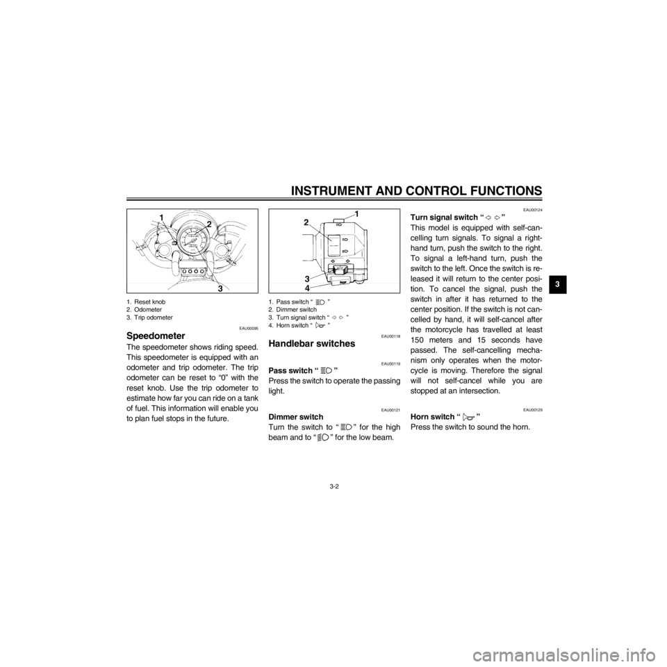
1. Reset knob
2. Odometer
3. Trip odometer
EAU00095
Speedometer
The speedometer shows riding speed.
This speedometer is equipped with an
odometer and trip odometer. The trip
odometer can be reset to Ò0Ó with the
reset knob. Use the trip odometer to
estimate how far you can ride on a tank
of fuel. This information will enable you
to plan fuel stops in the future.
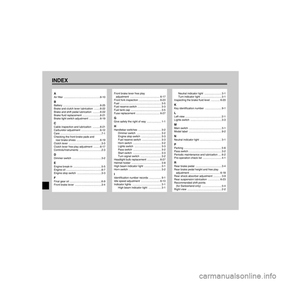
1. Pass switch Ò Ó
2. Dimmer switch
3. Turn signal switch Ò Ó
4. Horn switch Ò Ó
EAU00118
Handlebar switches
EAU00119
Pass switch Ò Ó
Press the switch to operate the passing
light.
EAU00121
Dimmer switch
Turn the switch to Ò Ó for the high
beam and to Ò Ó for the low beam.
EAU00124
Turn signal switch Ò Ó
This model is equipped with self-can-
celling turn signals. To signal a right-
hand turn, push the switch to the right.
To signal a left-hand turn, push the
switch to the left. Once the switch is re-
leased it will return to the center posi-
tion. To cancel the signal, push the
switch in after it has returned to the
center position. If the switch is not can-
celled by hand, it will self-cancel after
the motorcycle has travelled at least
150 meters and 15 seconds have
passed. The self-cancelling mecha-
nism only operates when the motor-
cycle is moving. Therefore the signal
will not self-cancel while you are
stopped at an intersection.
EAU00129
Horn switch Ò Ó
Press the switch to sound the horn.
Page 80 of 87

R
8-4
SPECIFICATIONS
/Net/layout8/layout_G2/work/Imai_work/OM-PS/AA9149_XV535-E6/English/E-8.frame
Bulb voltage, wattage ´
quantity
Headlight 12 V, 60/55 W ´ 1
Auxiliary light 12 V, 4 W ´ 1 (except for GB)
12 V, 3.4 W ´ 1(for GB)
Tail/brake light 12 V, 5/21 W ´ 2
Front ßasher light 12 V, 21 W ´ 2
Rear ßasher light 12 V, 21 W ´ 2
Meter light 14 V, 3 W ´ 1
Neutral indicator light 14 V, 3 W ´ 1
High beam indicator light 12 V, 1.7 W ´ 1
Turn indicator light 14 V, 3 W ´ 1
Fuses
Main fuse 30 A
Ignition fuse 15 A
Signaling system fuse 15 A
Headlight fuse 15 A
Page 85 of 87

L
INDEX
/Net/layout8/layout_G2/work/Imai_work/OM-PS/AA9149_XV535-E6/English/XV535IX.-
A
Air filter .................................................6-10
B
Battery ..................................................6-25
Brake and clutch lever lubrication ........6-22
Brake and shift pedal lubrication ..........6-22
Brake fluid replacement ........................6-21
Brake light switch adjustment ...............6-19
C
Cable inspection and lubrication ..........6-21
Carburetor adjustment ..........................6-12
Care ........................................................7-1
Checking the front brake pads and
rear brake shoes ................................6-19
Clutch lever ............................................3-3
Clutch lever free play adjustment .........6-17
Controls/Instruments ..............................2-3
D
Dimmer switch ........................................3-2
E
Engine break-in ......................................5-5
Engine oil ................................................6-7
Engine stop switch .................................3-3
F
Final gear oil ...........................................6-9
Front brake lever ....................................3-4
Front brake lever free play
adjustment ........................................ 6-17
Front fork inspection ............................ 6-23
Fuel ........................................................ 3-5
Fuel reserve switch ................................ 3-3
Fuel tank cap ......................................... 3-5
Fuse replacement ................................ 6-27
G
Give safety the right of way ................... 1-1
H
Handlebar switches ............................... 3-2
Dimmer switch ................................. 3-2
Engine stop switch ........................... 3-3
Fuel reserve switch .......................... 3-3
Horn switch ...................................... 3-2
Lights switch .................................... 3-3
Pass switch ...................................... 3-2
Start switch ...................................... 3-3
Turn signal switch ............................ 3-2
Headlight bulb replacement ................. 6-27
Helmet holder ........................................ 3-8
High beam indicator light ....................... 3-1
Horn switch ............................................ 3-2
I
Identification number records ................ 9-1
Idle speed adjustment ......................... 6-13
Indicator lights ....................................... 3-1
High beam indicator light ................. 3-1
Neutral indicator light ....................... 3-1
Turn indicator light ............................ 3-1
Inspecting the brake fluid level ............ 6-20
K
Key identification number ...................... 9-1
L
Left view ................................................. 2-1
Lights switch .......................................... 3-3
M
Main switch ............................................ 3-1
Model label ............................................ 9-2
N
Neutral indicator light ............................. 3-1
P
Parking ................................................... 5-6
Pass switch ............................................ 3-2
Periodic maintenance and lubrication .... 6-2
Pre-operation check list ......................... 4-1
R
Rear brake pedal ................................... 3-4
Rear brake pedal height and free play
adjustment ......................................... 6-18
Rear shock absorber adjustment ........... 3-9
Rear suspension lubrication ................ 6-23
Recommended shift points
(for Switzerland only) .......................... 5-4
Right view .............................................. 2-2