engine YAMAHA XV950 2014 Owner's Manual
[x] Cancel search | Manufacturer: YAMAHA, Model Year: 2014, Model line: XV950, Model: YAMAHA XV950 2014Pages: 88, PDF Size: 2.37 MB
Page 41 of 88
OPERATION AND IMPORTANT RIDING POINTS
5-4
5
1600 km (1000 mi) an
d b eyon d
The vehicle can now be operated nor-
mally.
NOTICE
ECA10271
If any en gine trou ble shoul d occur
d urin g the en gine break-in perio d,
imme diately have a Yamaha dealer
check the vehicle.
EAU17214
Parkin gWhen parking, stop the engine, and
then remove the key from the main
switch.
WARNING
EWA10312
Since the en gine an d exhaust
system can b ecome very hot,
park in a place where ped estri-
ans or chil dren are not likely to
touch them an d b e burne d.
Do not park on a slope or on soft
groun d, otherwise the vehicle
may overturn, increasin g the
risk of a fuel leak an d fire.
Do not park near grass or other
flamma ble materials which
mi ght catch fire.
U2DEE0E0.book Page 4 Friday, June 14, 2013 1:29 PM
Page 42 of 88
PERIODIC MAINTENANCE AND ADJUSTMENT
6-1
6
EAU17245
Periodic inspection, adjustment, and
lubrication will keep your vehicle in the
safest and most efficient condition
possible. Safety is an obligation of the
vehicle owner/operator. The most im-
portant points of vehicle inspection,
adjustment, and lubrication are ex-
plained on the following pages.
The intervals given in the periodic
maintenance charts should be simply
considered as a general guide under
normal riding conditions. However, de-
pending on the weather, terrain, geo-
graphical location, and individual use,
the maintenance intervals may need to
be shortened.
WARNING
EWA10322
Failure to properly maintain the vehi-
cle or performing maintenance ac-
tivities incorrectly may increase
your risk of injury or death durin g
service or while usin g the vehicle. If
you are not familiar with vehicle ser-
vice, have a Yamaha d ealer perform
service.
WARNING
EWA15123
Turn off the en gine when performin g
maintenance unless otherwise
specified .
A runnin g en gine has movin g
parts that can catch on body
parts or clothin g an d electrical
parts that can cause shocks or
fires.
Runnin g the en gine while ser-
vicin g can lead to eye injury,
b urns, fire, or car bon monoxi de
poisonin g – possi bly lea din g to
d eath. See pag e 1-3 for more in-
formation a bout car bon monox-
i d e.
WARNING
EWA15461
Brake discs, calipers, drums, and
linin gs can b ecome very hot d uring
use. To avoi d possi ble burns, let
b rake components cool before
touchin g them.
EAU17303
Emission controls not only function to
ensure cleaner air, but are also vital to
proper engine operation and maximum
performance. In the following periodic
maintenance charts, the services relat-
ed to emissions control are grouped
separately. These services require
specialized data, knowledge, and
equipment. Maintenance, replace-
ment, or repair of the emission control
devices and systems may be per-
formed by any repair establishment or
individual that is certified (if applicable).
Yamaha dealers are trained and equipped to perform these particular
services.
U2DEE0E0.book Page 1 Friday, June 14, 2013 1:29 PM
Page 49 of 88
PERIODIC MAINTENANCE AND ADJUSTMENT
6-8
6
EAU18752
Removing an d installin g the
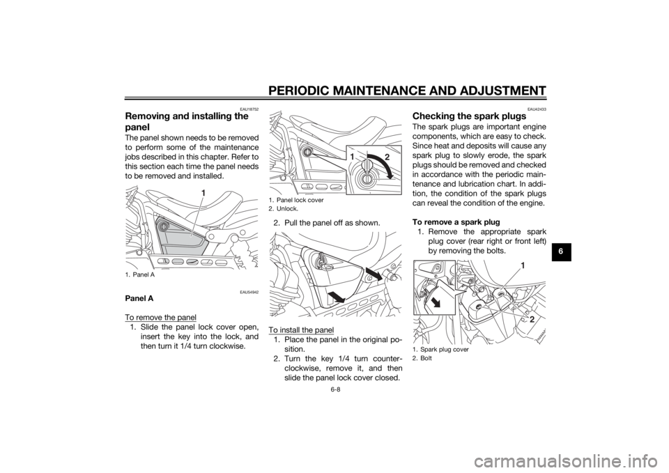
panelThe panel shown needs to be removed
to perform some of the maintenance
jobs described in this chapter. Refer to
this section each time the panel needs
to be removed and installed.
EAU54942
Panel A
To remove the panel1. Slide the panel lock cover open,
insert the key into the lock, and
then turn it 1/4 turn clockwise. 2. Pull the panel off as shown.
To install the panel
1. Place the panel in the original po- sition.
2. Turn the key 1/4 turn counter- clockwise, remove it, and then
slide the panel lock cover closed.
EAU42433
Checkin g the spark plu gsThe spark plugs are important engine
components, which are easy to check.
Since heat and deposits will cause any
spark plug to slowly erode, the spark
plugs should be removed and checked
in accordance with the periodic main-
tenance and lubrication chart. In addi-
tion, the condition of the spark plugs
can reveal the condition of the engine.
To remove a spark plu g
1. Remove the appropriate spark plug cover (rear right or front left)
by removing the bolts.
1. Panel A
1
1. Panel lock cover
2. Unlock.
1 2
1. Spark plug cover
2. Bolt
1
2
U2DEE0E0.book Page 8 Friday, June 14, 2013 1:29 PM
Page 50 of 88

PERIODIC MAINTENANCE AND ADJUSTMENT
6-9
62. Remove the spark plug cap.
3. Remove the spark plug as shown,
with the spark plug wrench includ-
ed in the additional tool kit, which
was handed out separately at the
purchase of the vehicle. To check the spark plu
gs
1. Check that the porcelain insulator around the center electrode on
each spark plug is a medium-to-
light tan (the ideal color when the
vehicle is ridden normally).
2. Check that all spark plugs in- stalled in the engine have the
same color.
TIPIf any spark plug shows a distinctly dif-
ferent color, the engine could be oper-
ating improperly. Do not attempt to
diagnose such problems yourself. In-
stead, have a Yamaha dealer check
the vehicle.
3. Check each spark plug for elec-trode erosion and excessive car-
bon or other deposits, and replace
it if necessary.
4. Measure the spark plug gap with a wire thickness gauge and, if nec-
essary, adjust the gap to specifi-
cation.
1. Spark plug cover
2. Bolt
1. Spark plug cap
2
1
1
1. Spark plug wrench
1
Specifie d spark plu g:
NGK/CPR7EA-91. Spark plug gapSpark plu g g ap:
0.8–0.9 mm (0.031–0.035 in)
U2DEE0E0.book Page 9 Friday, June 14, 2013 1:29 PM
Page 51 of 88
PERIODIC MAINTENANCE AND ADJUSTMENT
6-10
6
To install a spark plu
g
1. Clean the surface of the spark plug gasket and its mating sur-
face, and then wipe off any grime
from the spark plug threads.
2. Install the spark plug with the spark plug wrench, and then tight-
en it to the specified torque.
TIPIf a torque wrench is not available
when installing a spark plug, a good
estimate of the correct torque is 1/4–
1/2 turn past finger tight. However, the
spark plug should be tightened to the
specified torque as soon as possible.3. Install the spark plug cap.
4. Install the spark plug cover by in-stalling the bolts.
EAU47113
Engine oil an d oil filter car-
tri dgeThe engine oil level should be checked
before each ride. In addition, the oil
must be changed and the oil filter car-
tridge replaced at the intervals speci-
fied in the periodic maintenance and
lubrication chart.
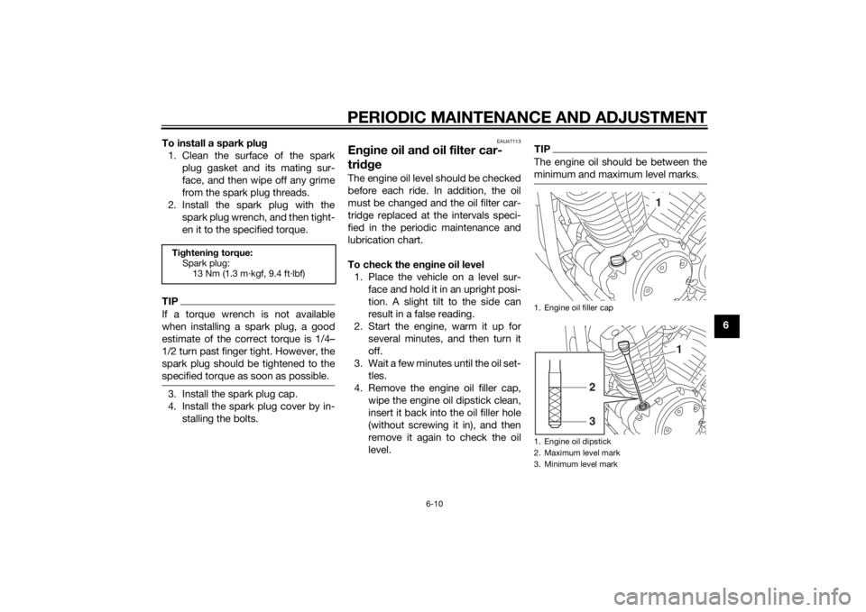
To check the en gine oil level
1. Place the vehicle on a level sur- face and hold it in an upright posi-
tion. A slight tilt to the side can
result in a false reading.
2. Start the engine, warm it up for several minutes, and then turn it
off.
3. Wait a few minutes until the oil set- tles.
4. Remove the engine oil filler cap, wipe the engine oil dipstick clean,
insert it back into the oil filler hole
(without screwing it in), and then
remove it again to check the oil
level.
TIPThe engine oil should be between the
minimum and maximum level marks.
Tightenin g torque:
Spark plug: 13 Nm (1.3 m·kgf, 9.4 ft·lbf)
1. Engine oil filler cap
1. Engine oil dipstick
2. Maximum level mark
3. Minimum level mark
1
1
32
U2DEE0E0.book Page 10 Friday, June 14, 2013 1:29 PM
Page 52 of 88
PERIODIC MAINTENANCE AND ADJUSTMENT
6-11
65. If the engine oil is at or below the
minimum level mark, add suffi-
cient oil of the recommended type
to raise it to the correct level.
6. Insert the dipstick into the oil filler hole, and then tighten the oil filler
cap.
To chan ge the en gine oil (with or
without oil filter cartri dge replace-
ment) 1. Start the engine, warm it up for several minutes, and then turn it
off.
2. Place an oil pan under the engine to collect the used oil.
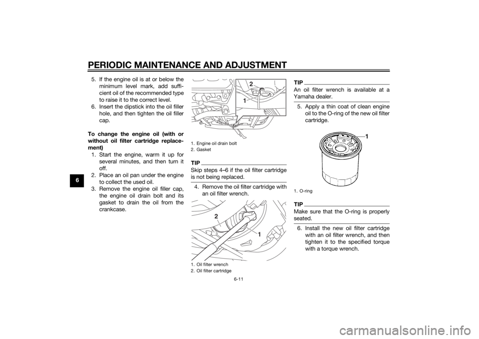
3. Remove the engine oil filler cap, the engine oil drain bolt and its
gasket to drain the oil from the
crankcase.
TIPSkip steps 4–6 if the oil filter cartridge
is not being replaced.4. Remove the oil filter cartridge withan oil filter wrench.
TIPAn oil filter wrench is available at a
Yamaha dealer.5. Apply a thin coat of clean engine oil to the O-ring of the new oil filter
cartridge.TIPMake sure that the O-ring is properly
seated.6. Install the new oil filter cartridgewith an oil filter wrench, and then
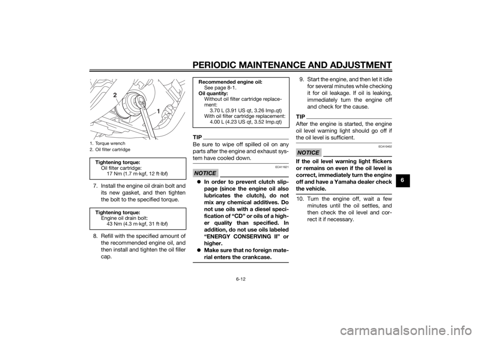
tighten it to the specified torque
with a torque wrench.
1. Engine oil drain bolt
2. Gasket
1. Oil filter wrench
2. Oil filter cartridge
2
1
1
2
1. O-ring
U2DEE0E0.book Page 11 Friday, June 14, 2013 1:29 PM
Page 53 of 88
PERIODIC MAINTENANCE AND ADJUSTMENT
6-12
6
7. Install the engine oil drain bolt and
its new gasket, and then tighten
the bolt to the specified torque.
8. Refill with the specified amount of the recommended engine oil, and
then install and tighten the oil filler
cap.
TIPBe sure to wipe off spilled oil on any
parts after the engine and exhaust sys-
tem have cooled down.NOTICE
ECA11621
In or der to prevent clutch slip-
pa ge (since the en gine oil also
lu bricates the clutch), do not
mix any chemical add itives. Do
not use oils with a diesel speci-
fication of “CD” or oils of a hi gh-
er quality than specified . In
a dd ition, do not use oils lab eled
“ENERGY CONSERVING II” or
hi gher.
Make sure that no forei gn mate-
rial enters the crankcase.
9. Start the engine, and then let it idle for several minutes while checking
it for oil leakage. If oil is leaking,
immediately turn the engine off
and check for the cause.TIPAfter the engine is started, the engine
oil level warning light should go off if
the oil level is sufficient.NOTICE
ECA10402
If the oil level warnin g li ght flickers
or remains on even if the oil level is
correct, imme diately turn the en gine
off an d have a Yamaha dealer check
the vehicle.10. Turn the engine off, wait a few minutes until the oil settles, and
then check the oil level and cor-
rect it if necessary.
1. Torque wrench
2. Oil filter cartridgeTightenin g torque:
Oil filter cartridge: 17 Nm (1.7 m·kgf, 12 ft·lbf)
Ti ghtenin g torque:
Engine oil drain bolt: 43 Nm (4.3 m·kgf, 31 ft·lbf)
1
2
Recommen ded en gine oil:
See page 8-1.
Oil quantity: Without oil filter cartridge replace-
ment:3.70 L (3.91 US qt, 3.26 Imp.qt)
With oil filter cartridge replacement:
4.00 L (4.23 US qt, 3.52 Imp.qt)
U2DEE0E0.book Page 12 Friday, June 14, 2013 1:29 PM
Page 55 of 88
PERIODIC MAINTENANCE AND ADJUSTMENT
6-14
6
EAU21402
Valve clearanceThe valve clearance changes with use,
resulting in improper air-fuel mixture
and/or engine noise. To prevent this
from occurring, the valve clearance
must be adjusted by a Yamaha dealer
at the intervals specified in the periodic
maintenance and lubrication chart.
EAU21567
TiresTires are the only contact between the
vehicle and the road. Safety in all con-
ditions of riding depends on a relatively
small area of road contact. Therefore, it
is essential to maintain the tires in good
condition at all times and replace them
at the appropriate time with the speci-
fied tires.
Tire air pressure
The tire air pressure should be
checked and, if necessary, adjusted
before each ride.
WARNING
EWA10504
Operation of this vehicle with im-
proper tire pressure may cause se-
vere injury or death from loss of
control. The tire air pressure must b e
checked and a djuste d on col d
tires (i.e., when the temperature
of the tires equals the am bient
temperature).
The tire air pressure must b e
a d juste d in accor dance with the
ri din g speed and with the total wei
ght of ri der, passen ger, car-
g o, an d accessories approve d
for this mo del.
WARNING
EWA10512
Never overloa d your vehicle. Opera-
tion of an overloa ded vehicle coul d
cause an acci dent.
Tire air pressure (measure d on col d
tires): 0–90 k g (0–198 l b):
Front:
225 kPa (2.25 kgf/cm², 33 psi)
Rear: 250 kPa (2.50 kgf/cm², 36 psi)
For non-ABS mo dels 90–206 k g
(198–454 l b)
For ABS mo dels 90–202 k g (198–
445 l b):
Front: 250 kPa (2.50 kgf/cm², 36 psi)
Rear: 280 kPa (2.80 kgf/cm², 41 psi)
Maximum loa d*:
For non-ABS models 206 kg (454
lb)
For ABS models 202 kg (445 lb)
* Total weight of rider, passenger, car- go and accessories
U2DEE0E0.book Page 14 Friday, June 14, 2013 1:29 PM
Page 66 of 88
PERIODIC MAINTENANCE AND ADJUSTMENT
6-25
6
EAU23284
Checking the steerin gWorn or loose steering bearings may
cause danger. Therefore, the operation
of the steering must be checked as fol-
lows at the intervals specified in the
periodic maintenance and lubrication
chart.
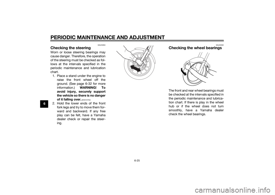
1. Place a stand under the engine to raise the front wheel off the
ground. (See page 6-32 for more
information.) WARNING! To
avoi d injury, securely support
the vehicle so there is no dan ger
of it fallin g over.
[EWA10752]
2. Hold the lower ends of the front
fork legs and try to move them for-
ward and backward. If any free
play can be felt, have a Yamaha
dealer check or repair the steer-
ing.
EAU23292
Checkin g the wheel bearin gsThe front and rear wheel bearings must
be checked at the intervals specified in
the periodic maintenance and lubrica-
tion chart. If there is play in the wheel
hub or if the wheel does not turn
smoothly, have a Yamaha dealer
check the wheel bearings.
U2DEE0E0.book Page 25 Friday, June 14, 2013 1:29 PM
Page 73 of 88
PERIODIC MAINTENANCE AND ADJUSTMENT
6-32
6
EAU45226
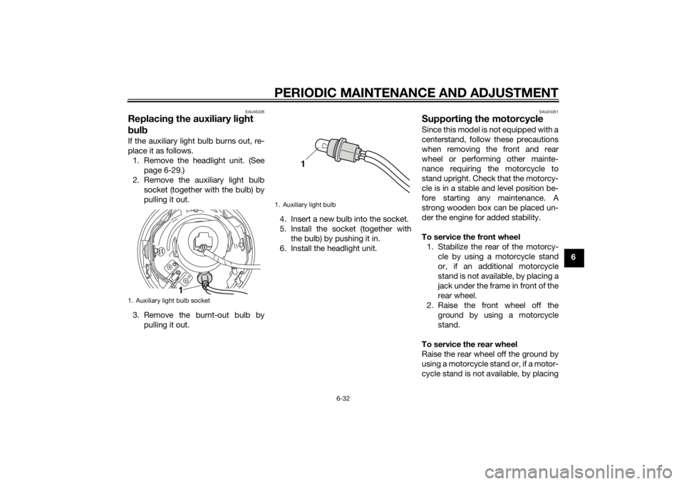
Replacing the auxiliary li ght
b ul b If the auxiliary light bulb burns out, re-
place it as follows.
1. Remove the headlight unit. (See page 6-29.)
2. Remove the auxiliary light bulb socket (together with the bulb) by
pulling it out.
3. Remove the burnt-out bulb by pulling it out. 4. Insert a new bulb into the socket.
5. Install the socket (together with
the bulb) by pushing it in.
6. Install the headlight unit.
EAU24351
Supportin g the motorcycleSince this model is not equipped with a
centerstand, follow these precautions
when removing the front and rear
wheel or performing other mainte-
nance requiring the motorcycle to
stand upright. Check that the motorcy-
cle is in a stable and level position be-
fore starting any maintenance. A
strong wooden box can be placed un-
der the engine for added stability.
To service the front wheel
1. Stabilize the rear of the motorcy- cle by using a motorcycle stand
or, if an additional motorcycle
stand is not available, by placing a
jack under the frame in front of the
rear wheel.
2. Raise the front wheel off the ground by using a motorcycle
stand.
To service the rear wheel
Raise the rear wheel off the ground by
using a motorcycle stand or, if a motor-
cycle stand is not available, by placing
1. Auxiliary light bulb socket
1
1. Auxiliary light bulb
1
U2DEE0E0.book Page 32 Friday, June 14, 2013 1:29 PM